Transcription
INSTALLATION INSTRUCTIONSA95UH2V & 95G2UHVWarm Air Gas FurnaceUpflow/Horizontal Left Air DischargeDirect Vent OnlyThis manual must be left with the homeowner for future reference.This is a safety alert symbol and should never be ignored. When you see this symbol on labels or inmanuals, be alert to the potential for personal injury or death.WARNINGCAUTIONImproper installation, adjustment, alteration, service ormaintenance can cause property damage, personal injuryor loss of life. Installation and service must be performedby a licensed professional installer (or equivalent), serviceagency or the gas supplier.As with any mechanical equipment, personal injury canresult from contact with sharp sheet metal edges. Becareful when you handle this equipment.TABLE OF CONTENTSUnit Dimensions . 2A95UH2V/95G2UHV Parts Arrangement . 3A95UH2V/95G2UHV Gas Furnace . 4Shipping and Packing List . 4Safety Information . 4Use of Furnace as a Construction Heater . 5General . 6Shipping Bolt Removal . 7Setting Equipment . 7Removing Bottom Panel . 9Upflow Application ONLY . 9Horizontal Application ONLY . 9Filters . 11Duct System . 11Pipe and Fittings Specifications . 11Canadian Applications ONLY . 12Joint Cementing Procedure . 13Venting Practices . 14Vent Piping Guidelines . 15Gas Piping . 27Electrical . 30Failure Codes . 35Unit Start Up . 38Gas Valve Operation . 39Heating Sequence of Operation . 39High Altitude Information . 40Other Unit Adjustments . 41Blower Data . 42Service . 46Planned Service . 48Repair Parts List . 49Start Up Checklist . 50Manufactured ByAllied Air Enterprises, Inc.A Lennox International, Inc. Company215 Metropolitan DriveWest Columbia, SC 29170*p506787-01*(P) 506787-01506787-01Issue 1135Page 1 of 52
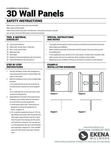
A95UH2V & 95G2UHV Unit Dimensions - inches (mm)1 NOTE - 20 C/D (5 Ton) size units installed in upflowapplications that require air volumes of 1800 cfm (850 L/s) orgreater must have one of the following:1. Single side return air with transition, to accommodate20 x 25 x 1 in. (508 x 635 x 25 mm) air filter.2. Single side return air with optional RAB Return Air Base3. Bottom return air.4. Return air from both sides.5. Bottom and one side return air.2 Optional External Side Return Air Filter kit is not for use withoptional Return Air Base.* Consider sizing requirements for optional IAQ equipmentbefore cutting side return opening.FRONT VIEWModelA95UH2V/95G2UHV045-12SIDE 16110-20135-20Page 2 of 52Issue 1135506787-01
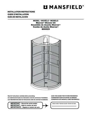
EXPANDED VIEWFigure 1506787-01Issue 1135Page 3 of 52
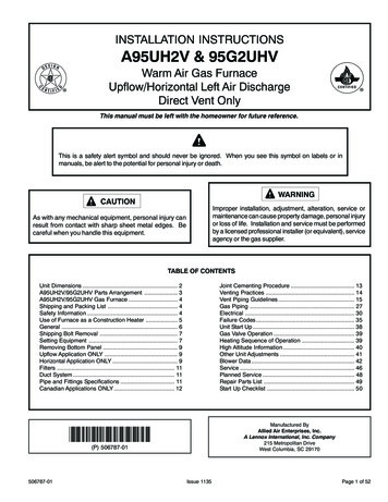
A95UH2V & 95G2UHV Gas FurnaceThe A95UH2V/95G2UHV Category IV gas furnace isshipped ready for installation in the upflow or horizontalposition. The furnace is shipped with the bottom panel inplace. The bottom panel must be removed if the unit is tobe installed in horizontal or upflow applications with bottomreturn air.Safety InformationWARNINGImproper installation, adjustment, alteration, service ormaintenance can cause property damage, personal injuryor loss of life. Installation and service must be performedby a licensed professional installer (or equivalent), serviceagency or the gas supplier.The A95UH2V/95G2UHV must be installed as a DirectVent Gas Central Furnace.The furnace is equipped for installation in natural gasapplications. A conversion kit (ordered separately) is requiredfor use in propane/LP gas applications.CAUTIONAs with any mechanical equipment, personal injury canresult from contact with sharp sheet metal edges. Becareful when you handle this equipment.NOTE: In Direct Vent installations, combustion air is takenfrom outdoors and flue gases are discharged outdoors. SeeFigure 2 for applications involving roof termination.DANGERDANGER OF EXPLOSION!There are circumstances in which odorant used with LP/Propane gas can lose its scent. In case of a leak, LP/Propane gas will settle close to the floor and may be difficultto smell. An LP/Propane leak detector should be installedin all LP applications.Use only the type of gas approved for use with this furnace.Refer to unit nameplate.A95UH2V/95G2UHV units are CSA International certifiedto ANSI Z21.47 and CSA 2.3 standards.Figure 2Building CodesIn the USA, installation of gas furnaces must conform withlocal building codes. In the absence of local codes, unitsmust be installed according to the current National Fuel GasCode (ANSI Z223.1/NFPA 54). The National Fuel Gas Codeis available from the American National StandardsInstitute, Inc., 11 West 42nd Street, New Your, NY 10036.Shipping and Packing List1 - Assembled Gas Furnace1 - Bag assembly containing the following:1 - Snap bushing1 - Snap Plug1 - Wire tie1 - Condensate trap1 - Condensate trap cap1 - Condensate trap clamp1 - 2” Diameter debris screenIn Canada, installation must conform with current NationalStandard of Canada CSA-B149 Natural Gas and PropaneInstallation Codes, local plumbing or waste water codes andother applicable local codes.Check equipment for shipping damage. If you find anydamage, immediately contact the last carrier.In order to ensure proper unit operation in non-direct ventapplications, combustion and ventilation air supply must beprovided according to the current National Fuel Gas Codeor CSA-B149 standard.Please refer to specification sheets for available accessories.Page 4 of 52Issue 1135506787-01
Installed LocationsThis furnace is CSA International certified for installationclearances to combustible material as listed on the unitnameplate and in the table in Figure 6. Accessibility andservice clearances must take precedence over fire protectionclearances.Heating Unit Installed Parallel to Air Handler UnitNOTE: For installation on combustible floors, the furnaceshall not be installed directly on carpeting, tile, or othercombustible material other than wood flooring.For installation in a residential garage, the furnace must beinstalled so that the burner(s) and the ignition source arelocated no less than 18 inches (457 mm) above the floor.The furnace must be located or protected to avoid physicaldamage by vehicles. When a furnace is installed in a publicgarage, hangar, or other building that has a hazardousatmosphere, the furnace must be installed according torecommended good practice requirements and currentNational Fuel Gas Code or CSA B149 standards.Heating Unit Installed Upstream of Cooling UnitNote: Furnace must be adjusted to obtain a temperaturerise within the range specified on the unit nameplate. Failureto do so may cause erratic limit operation and prematureheat exchanger failure.This furnace must be installed so that its electricalcomponents are protected from water.Installed in Combination with a Cooling CoilWhen this furnace is used with cooling units (Figure 3), itshall be installed in parallel with, or on the upstream side of,cooling units to avoid condensation in the heatingcompartment. With a parallel flow arrangement, a damper(or other means to control the flow of air) must adequatelyprevent chilled air from entering the furnace. If the damperis manually operated, it must be equipped to preventoperation of either the heating or the cooling unit, unless itis in the full HEAT or COOL setting.When installed, this furnace must be electrically groundedaccording to local codes. In addition, in the United States,installation must conform with the current National ElectricCode, ANSI/NFPA No. 70. The National Electric Code (ANSI/NFPA No. 70) is available from the following address:National Fire Protection Association1 Battery March ParkQuincy, MA 02269NOTE: This furnace is designed for a minimum continuousreturn air temperature of 60 F (16 C) or an intermittentoperation down to 55 F (13 C) dry bulb for cases where anight setback thermostat is used. Return air temperaturemust not exceed 85 F (29 C) dry bulb.This furnace may be installed in alcoves, closets, attics,basements, garages, and utility rooms in the upflow orhorizontal position.This furnace design has not been CSA certified for installationin mobile homes, recreational vehicles, or outdoors.Use of Furnace as a Construction HeaterThese units are not recommended for construction heaterduring any phase of construction. Very low return airtemperature, harmful vapors and operation of the unit withclogged or misplaced filters will damage the unit.These units may be used for heating of buildings or structuresunder construction, if the following conditions are met: The vent system must be permanently installed per theseinstallation instructions. A room thermostat must control the furnace. The use offixed jumpers that will provide continuous heating is notallowed. The return air duct must be provided and sealed to thefurnace. Return air temperature range between 60 F (16 C) and80 F (27 C) must be maintained.Issue 1135Page 5 of 52In Canada, all electrical wiring and grounding for the unitmust be installed according to the current regulations of theCanadian Electrical Code Part I (CSA Standard C22.1) and/or local codes.506787-01Figure 3
Air filters must be installed in the system and must bemaintained during construction. Air filters must be replaced upon construction completion.Product Contains Fiberglass Wool. The input rate and temperature rise must be set per thefurnace rating plate. One hundred percent (100%) outdoor air must be providedfor combustion air requirements during construction.Temporary ducting may supply outdoor air to the furnace.Do not connect duct directly to the furnace. Size thetemporary duct following the instructions in section forCombustion, Dilution and Ventilation Air in a confinedspace with air from outside. The furnace heat exchanger, components, duct system,air filters and evaporator coils must be thoroughlycleaned following final construction cleanup.Disturbing the insulation in this product duringinstallation, maintenance, or repair will expose you tofiberglass wool. Breathing this may cause lung cancer.(Fiberglass wool is known to the State of California tocause cancer.)Fiberglass wool may also cause respiratory, skin, andeye irritation.To reduce exposure to this substance or for furtherinformation, consult material safety data sheets availablefrom address shown below, or contact your supervisor.Allied Air Enterprises, Inc.215 Metropolitan DriveWest Columbia, SC 29170 All furnace operating conditions (including ignition, inputrate, temperature rise and venting) must be verifiedaccording to these installation instructions.WARNINGGeneralThese instructions are intended as a general guide and donot supersede local codes in any way. Consult authoritieshaving jurisdiction before installation.In addition to the requirements outlined previously, thefollowing general recommendations must be consideredwhen installing one of these furnaces: Place the furnace as close to the center of the airdistribution system as possible. The furnace should alsobe located close to the chimney or vent termination point. When the furnace is installed in an attic or other insulatedspace, keep insulation away from the furnace. When the furnace is installed in an unconditioned space,consider provisions required to prevent freezing ofcondensate drain system.CAUTIONThese units should not be installed in areas normallysubject to freezing temperatures.Page 6 of 52Issue 1135506787-01
Shipping Bolt RemovalUnits with 1/2 hp blower motor are equipped with threeflexible legs and one rigid leg. The rigid leg is equipped witha shipping bolt and a flat white plastic washer (rather thanthe rubber mounting grommet used with a flexible mountingleg). See Figure 4. The bolt and washer must be removedbefore the furnace is placed into operation. After thebolt and washer have been removed, the rigid leg will nottouch the blower housing.INSTALLATIONSetting EquipmentWARNINGDo not connect the return air ducts to the back of thefurnace. Doing so will adversely affect the operation ofthe safety control devices, which could result in personalinjury or death.WARNINGUnits with 1/2 HPBlower MotorFigure 4Blower access panel must be securely in place whenblower and burners are operating. Gas fumes, whichcould contain carbon monoxide, can be drawn into livingspace resulting in personal injury or death.Upflow ApplicationsThe gas furnaces can be installed as shipped in the upflowposition. Refer to Figure 6 for clearances. Select a locationthat allows for the required clearances that are listed on theunit nameplate. Also consider gas supply connections,electrical supply, vent connection, condensate trap and drainconnections, and installation and service clearances [24inches (610 mm) at unit front]. The unit must be level fromside to side. Tilt the unit slightly (maximum 1/2 in. fromlevel) from back to front to aid in the draining of the heatexchanger. See Figure 5.Allow for clearances to combustible materials as indicatedon the unit nameplate.SETTING EQUIPMENTUnit must be level side-to-side in all applications.Tilt the unit slightly (Max. 1/2”) from back to front to aid in the draining ofthe heat exchanger.Figure 5506787-01Issue 1135Page 7 of 52
WARNINGImproper installation of the furnace can result in personalinjury or death. Combustion and flue products mustnever be allowed to enter the return air system or air inthe living space. Use sheet metal screws and joint tapeto seal return air system to furnace.In platform installations with furnace return, the furnaceshould be sealed airtight to the return air plenum. Adoor must never be used as a portion of the return airduct system. The base must provide a stable supportand an airtight seal to the furnace. Allow absolutely nosagging, cracks, gaps, etc.For no reason should return and supply air duct systemsever be connected to or from other heating devices suchas a fireplace or stove, etc. Fire, explosion, carbonmonoxide poisoning, personal injury and/or propertydamage could result.Return Air GuidlinesReturn air can be brought in through the bottom or eitherside of the furnace installed in an upflow application. If thefurnace is installed on a platform with bottom return, makean airtight seal between the bottom of the furnace and theplatform to ensure that the furnace operates properly andsafely. The furnace is equipped with a removable bottompanel to facilitate installation.Markings are provided on both sides of the furnace cabinetfor installations that require side return air. Cut the furnacecabinet at the maximum dimensions shown on page 2.Furnace applications which include side return air and acondensate trap installed on the same side of the cabinet(trap can be installed remotely within 5 ft.) require either areturn air base or field-fabricated transition to accommodatean optional IAQ accessory taller than 14.5”. See Figure 7.Side Return Air(with transition and filter)Installation Clearances1 in. (25 mm)Top/Plenum* Front0Back0Sides0†Vent0Floor0‡Figure 7* Front clearance in alcove installation must be 24 in. (610 mm).Maintain a minimum of 24 in. (610 mm) for front service access.† Allow proper clearances to accommodate condensate trap and ventpipe installation.‡ For installations on a combustible floor, do not install the furnacedirectly on carpeting, tile or other combustible materials other thanwood flooring.Figure 6Page 8 of 52Issue 1135506787-01
Optional Return Air Base(Upflow Applications Only)SIDE VIEWFRONT VIEWNOTE: Optional side return air filter kits are not for use with return air base.1 Both the unit return air opening and the base return air opening must be covered by a single plenum or IAQ cabinet.Minimum unit side return air opening dimensions for units requiring 1800 cfm or more of air (W x H): 23 x 11 in. (584 x 279 mm).The opening can be cut as needed to accommodate plenum or IAQ cabinet while maintaining dimensions shown.Side return air openings must be cut in the field. There are cutting guides stenciled on the cabinet for the side return air opening.The size of the opening must not extend beyond the markings on the furnace cabinet.2 To minimize pressure drop, the largest opening height possible (up to 14 inches) is preferred.Figure 8panel. Once the bottom panel has been removed, reinstallthe bottom cap. See Figure 9.Removing the Bottom PanelHorizontal ApplicationsWARNINGDo not install the furnace on its front or its back. SeeFigure 10.Figure 9Figure 10Removing the Bottom PanelRemove the two screws that secure the bottom cap to thefurnace. Pivot the bottom cap down to release the bottom506787-01This furnace can be installed in horizontal applications witheither right or left hand air discharge.Refer to Figure 11 for clearances in horizontal applications.Issue 1135Page 9 of 52
Typical Horizontal ApplicationHorizontal ApplicationInstallation ClearancesRight-Hand DischargeFigure 120Top* Front0Back0Ends0Vent0Floor0‡NOTE: When the furnace is installed on a platform or withthe horizontal suspension kit in a crawl space, it must beelevated enough to avoid water damage, accommodate draintrap and to allow the evaporator coil to drain.* Front clearance in alcove installation must be 24 in. (610 mm).Maintain a minimum of 24 in. (610 mm) for front service access.** An 8” service clearance must be maintained below the unit to providefor servicing of the condensate trap unless the trap is mountedremotely.‡ For installations on a combustible floor, do not install the furnacedirectly on carpeting, tile or other combustible materials other thanwood flooring.Figure 11Suspended Installation of Horizontal UnitThis furnace may be installed in either an attic or a crawlspace. Either suspend the furnace from roof rafters or floorjoists, as shown in Figure 12, or install the furnace on aplatform, as shown in Figure 13. A horizontal suspension kit(51W10) may be ordered from your distributor or useequivalent.Platform Installation of Horizontal Unit1. Select location for unit keeping in mind service and othernecessary clearances. See Figure 11.2. Construct a raised wooden frame and cover frame witha plywood sheet. If unit is installed above finished space,fabricate an auxiliary drain pan to be installed under unit.Set unit in drain pan as shown in Figure 13. Leave 8inches for service clearance below unit for condensatetrap.3. Provide a service platform in front of unit. When installingthe unit in a crawl space, a proper support platform maybe created using cement blocks.4. Route auxiliary drain line so that water draining fromthis outlet will be easily noticed by the homeowner.5. If necessary, run the condensate line into a condensatepump to meet drain line slope requirements. The pumpmust be rated for use with condensing furnaces. Protectthe condensate discharge line from the pump to theoutside to avoid freezing.6. Continue with exhaust, condensate and intake pipinginstallation according to instructions.NOTE: Heavy-gauge sheet metal straps may be used tosuspend the unit from roof rafters or ceiling joists. Whenstraps are used to suspend the unit in this way, supportmust be provided for both the ends. The straps must notinterfere with the plenum or exhaust piping installation.Cooling coils and supply and return air plenums mustbe supported separately.Page 10 of 52Issue 1135506787-01
Duct SystemUse industry approved standards to size and install thesupply and return air duct system. This will result in a quietand low-static system that has uniform air distribution.NOTE: This furnace is not certified for operation in heatingmode (indoor blower operating at selected heating speed)with an external static pressure which exceeds 0.8 inchesw.c. Operation at these conditions may result in improperlimit operation.Supply Air PlenumIf the furnace is installed without a cooling coil, a removableaccess panel should be installed in the supply air duct. Theaccess panel should be large enough to permit inspection(by reflected light) of the heat exchanger for leaks after thefurnace is installed. The furnace access panel must alwaysbe in place when the furnace is operating and it must notallow leaks into the supply air duct system.Figure 13Return Air - Horizontal ApplicationsReturn air may be brought in only through the end of a furnaceinstalled in the horizontal position. The furnace is equippedwith a removable bottom panel to facilitate installation. SeeFigure 9.FiltersThis unit is not equipped with a filter or rack. A field providedfilter is required for the unit to operate properly. Table 1 listrecommended filter sizes.A filter must be in place whenever the unit is operating.Table 1Return Air PlenumNOTE: Return air must not be drawn from a room wherethis furnace, or any other gas fueled appliance (i.e., waterheater), or carbon monoxide producing device (i.e.,wood fireplace) is installed.When return air is drawn from a room, a negative pressureis created in the room. If a gas appliance is operating in aroom with negative pressure, the flue products can be pulledback down the vent pipe and into the room. This reverseflow of the flue gas may result in incomplete combustionand the formation of carbon monoxide gas. This raw gas ortoxic fumes might then be distributed throughout the houseby the furnace duct system.Return air can be brought in through the bottom or eitherside of the furnace. If a furnace with bottom return air isinstalled on a platform, make an airtight seal between thebottom of the furnace and the platform to ensure that theunit operates properly and safely. Use fiberglass sealingstrips, caulking, or equivalent sealing method between theplenum and the furnace cabinet to ensure a tight seal. If afilter is installed, size the return air duct to fit the filter frame.Pipe & Fittings SpecificationsAll pipe, fittings, primer and solvent cement must conformwith American National Standard Institute and the AmericanSociety for Testing and Materials (ANSI/ASTM) standards.The solvent shall be free flowing and contain no lumps,undissolved particles or any foreign matter that adverselyaffects the joint strength or chemical resistance of thecement. The cement shall show no gelation, stratification,or separation that cannot be removed by stirring. Refer toTable 2 for approved piping and fitting materials.506787-01Issue 1135Page 11 of 52
CAUTIONIMPORTANTSolvent cements for plastic pipe are flammable liquidsand should be kept away from all sources of ignition. Donot use excessive amounts of solvent cement whenmaking joints. Good ventilation should be maintained toreduce fire hazard and to minimize breathing of solventvapors. Avoid contact of cement with skin and eyes.A95UH2V/95G2UHV exhaust and intake connections aremade of PVC. Use PVC primer and solvent cement whenusing PVC vent pipe. When using ABS vent pipe, usetransitional solvent cement to make connections to thePVC fitting in the unit.PIPING AND FITTINGS SPECIFICATIONSUse PVC primer and solvent cement or ABS solvent cementmeeting ASTM specifications, refer to Table 2. As analternate, use all purpose cement, to bond ABS, PVC, orCPVC pipe when using fittings and pipe made of the samematerials. Use transition solvent cement when bonding ABSto either PVC or CPVC.Low temperature solvent cement is recommended duringcooler weather. Metal or plastic strapping may be used forvent pipe hangers. Uniformly apply a liberal coat of PVCprimer for PVC or use a clean dry cloth for ABS to cleaninside socket surface of fitting and male end of pipe to depthof fitting socket.Canadian Applications OnlyPipe, fittings, primer and solvent cement used to vent(exhaust) this appliance must be certified to ULC S636 andsupplied by a single manufacturer as part of an approvedvent (exhaust) system. When bonding the vent system tothe furnace, use ULC S636 approved One-Step TransitionCement to bond the pipe to the flue collar, or to bond the 90 elbow or reducing 90 elbow to the flue collar. In addition,the first three feet of vent pipe from the furnace flue collarmust be accessible for inspection.Table 2Page 12 of 52Issue 1135506787-01
OUTDOOR TERMINATION KITS USAGETable 3Joint Cementing ProcedureAll cementing of joints should be done according to thespecifications outlined in ASTM D 2855.DANGERDANGER OF EXPLOSION!Fumes from PVC glue may ignite during system check.Allow fumes to dissipate for at least 5 minutes beforeplacing unit into operation.506787-011. Measure and cut vent pipe to desired length.2. Debur and chamfer end of pipe, removing any ridges orrough edges. If end is not chamfered, edge of pipemay remove cement from fitting socket and result in aleaking joint.3. Clean and dry surfaces to be joined.4. Test fit joint and mark depth of fitting on outside of pipe.5. Uniformly apply a liberal coat of PVCD primer for PVCor use a clean dry cloth for ABS to clean inside socketsurface of fitting and male end of pipe to depth of fittingsocket.NOTE: Time is critical at this stage. Do not allow primer todry before applying cement.Issue 1135Page 13 of 52
6. Promptly apply solvent cement to end of pipe and insidesocket surface of fitting. Cement should be appliedlightly but uniformly to inside of socket. Take care tokeep excess cement out of socket. Apply second coatto end of pipe.7. Immediately after applying last coat of cement to pipe,and while both inside socket surface and end of pipeare wet with cement, forcefully insert end of pipe intosocket until it bottoms out. Turn PVC pipe 1/4 turn duringassembly (but not after pipe is fully inserted) to distributecement evenly. Do not turn ABS or cellular core pipe.NOTE: Assembly should be completed within 20 secondsafter last application of cement. Hammer blows should notbe used when inserting pipe.8. After assembly, wipe excess cement from pipe at endof fitting socket. A properly made join will show a beadaround its entire perimeter. Any gaps may indicate animproper defective assembly due to insufficient solvent.9. Handle joints carefully until completely set.Exhaust Piping1. In areas where piping penetrates joist or interior walls,hole must be large enough to allow clearance on all sidesof pipe through center of hole using a hanger.2. When furnace is installed in a residence where unit isshut down for an extended period of time, such as avacation home, make provisions for draining condensatecollection from trap and lines.Removal of the Furnace from Common VentIn the event that an existing furnace is removed from aventing system commonly run with separate gas appliances,the venting system is likely to be too large to properly ventthe remaining attached appliances.Conduct the following test while each appliance is operatingand the other appliances (which are not operating) remainconnected to the common venting system. If the ventingsystem has been installed improperly, you must correct thesystem as indicated in the general venting requirementssection.Venting PracticesWARNINGPiping Suspension GuidelinesCARBON MONOXIDE POISONING HAZARDFailure to follow the steps outlined below for eachappliance connected to the venting system being placedinto operation could result in carbon monoxidepoisoning or death.The following steps shall be followed for each applianceconnected to the venting system being placed intooperation, while all other appliances connected to 1heventing system are not in operation:NOTE: Isolate piping at the point where it exits the outside wall orroof in order to prevent transmission of vibration to the structure.Wall Thickness Guidelines1. Seal any unused openings in the common ventingsystem.2. Inspect the venting system for proper size and horizontalpitch. Determine that there is no blockage, restriction,leakage, corrosion, or other deficiencies which couldcause an unsafe condition.Figure 14Page 14 of 52Issue 1135506787-01
3. Close all building doors and windows and all doorsbetween the space in which the appliances remainingconnected to the common venting system are locatedand other spaces of the building. Turn on clothes dryersand any appliances not connected to the commonventing system. Turn on any exhaust fans, such asrange hoods and bathroom exhausts, so they willoperate at maximum speed. Do not operate a summerexhaust fan. Close fireplace dampers.Exhaust PipingRoute piping to outside of structure. Continue with installationfollowing instructions given in piping termination section.CAUTIONDo Not discharge exhaust
This manual must be left with the homeowner for future reference. INSTALLATION INSTRUCTIONS A95UH2V & 95G2UHV Warm Air Gas Furnace Upflow/Horizontal Left Air Discharge Direct Vent Only This is a safety alert symbol and should never be ignored. When you see this symbol on labels or in manuals, be alert to the potential for personal injury or death.