Transcription
US 10SSGTIMKENSE A L SPE CIF ICATION GUIDEA LEADER IN SEAL TECHNOLOGYSEALSInch/MetricV-SealsOil Bath SealsKWIK-Sleeves - ComponentsSeal KitsO-RingsSE A L S PE C IF I CAT ION G UID ETimken is the registered trademark ofThe Timken Company.www.timken.comwww.timkeninfo.com 2001 The Timken CompanyPrinted In the U.S.A.60M-12-01-11 Order No. 7533WORLDWIDE LEADER IN BEARINGS AND STEELTHE TIMKEN COMPANY
SEAL SPECIFICATION GUIDEINTRODUCTIONThe Timken Company, known for its top-quality line of bearings, has extended its product line to include seals. Timken,with 77 seal patents, already had the product knowledge forseal design. In fact, it was only natural for Timken to extendthis experience into a complete line of seals for the automotive aftermarket. Each and every seal sold by Timken is manufactured with the same quality that goes into every Timkenbearing. To help our customers in seal selection, we havedeveloped this Seal Specification Guide. If you have comments or suggestions on the Seal Specification Guide,please complete the postage paid card found in the back ofthis publication or send an e-mail to auto-am@timken.com.HOW TO USE THIS CATALOGThe seals listed in this catalog are arranged by shaft sizeand part number. Determine the method you will use for yoursearch, then turn to the corresponding section found in thetable of contents. Each seal will have the dimensions, alongwith the seal type and material. If a specific seal is not found,contact your Timken sales representative to checkthe availability of that particular seal.The data presented here is to provide a guideline or reference for general information only, it is not intended to beused for engineering purposes. Therefore, when installingany parts referenced in this catalog always follow the originalequipment manufacturer’s instruction manual, specificationsand guidelines. The information referenced is deemed reliablebut not guaranteed. The Timken Corporation reserves theright to make changes to, and amendments of, any information displayed. The Timken Corporation also reserves theright to make any functional substitutions in type, style ordesign where deemed appropriate. 2001 The Timken CorporationPortions of this book are 2000 Freudenberg-NOK and reprinted with permissionGENERAL GUIDELINESThe data provided here is a guideline for theselection of a seal for a general or specificapplication. The user needs to be aware thatmany seal design configurations exist tomeet specific requirements. Therefore, firstlook-up the correct seal in the Bearing andSeal Application Catalog for Automotive andLight Truck, published by The TimkenCorporation. If you do not find the informationregarding the seal required:1. Determine the general category theseal application falls within.2. Determine if operating conditionsexceed the design limits.a. Shaft Speedb. Pressurec. Eccentricity3. Select appropriate lip, case and material.Selection is based on temperature ofapplication, fluid and environment to besealed or excluded.4. Review bore and shaft configurationsto ensure compatibility with seal.5. If any questions or concerns remain,contact your Timken sales representativefor more information or assistance.WARNINGProper maintenance and handling practices are critical. Follow the equipmentmanufacturer’s installation instructions.Failure to follow installation instructionsand to maintain proper lubrication canresult in equipment failure and could leadto a risk of serious bodily harm.
TABLE OF CONTENTSSECTION. . . . . . . . . . . . . . . . . . . . . . . . . . . . . . . . . . . . . . . . . . . . . . . . . . . . . . . . . PAGEIntroduction.Inside Front CoverHow to Use This Catalog.Inside Front CoverGeneral Guidelines.Inside Front CoverWarning .Inside Front CoverSeal Nomenclature .2Seal Design Types.3-4, Inside Back CoverShaft Recommendations.5Housing Recommendations.6Bore Recommendations .7Operating Conditions .8-9Seal Tolerances.10Material Selection .11Seal Installation .12-13V-Seals.14KWIK-Sleeve - Component .15Conversion Chart .16Size Section – Seals – Inch/Metric.17-76Size Section – V-Seals .77-84Size Section – Oil Bath Seals.85-87Size Section – KWIK-Sleeves.88-93Size Section – Seal Kits .94-97Numeric Section – Seals-Inch .98-144Numeric Section – Seals-Metric .145-150Numeric Section – V-Seals .151-158Numeric Section – Oil Bath Seals .159-161Numeric Section – KWIK-Sleeves .162-167Numeric Section – Seal Kits.168-171Metric – Size.172-183Metric – Part .184-195O-Rings.196-1981
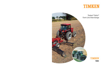
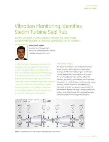
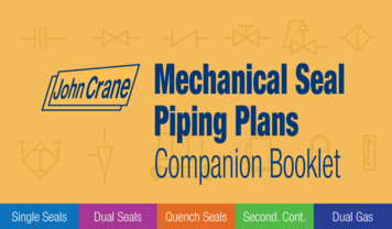
SEAL .17.18.2Seal WidthMetal Case (Outer)HousingInner CaseOutside FaceLip LengthInside FaceRadial Wall DimensionSeal Outer DiameterHousing Bore DiameterSpring Position (R-Value)Spring GrooveGarter SpringAxial ClearanceHeel SectionFlex SectionSpring Retainer LipHead 3.34.35.Inside Lip AngleToe FaceInside Case Inner DiameterOuter Case Inner DiameterAuxiliary (Dust) LipOutside Lip SurfaceOutside Lip AngleRib (Helix)Contact PointStatic LipInside Lip SurfaceMolded Toe AngleSpring Set Lip DiameterFree Lip (Unsprung) DiameterContact Line HeightLip HeightLip Angle
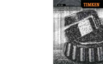
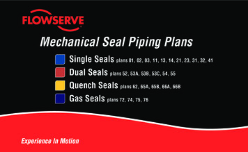
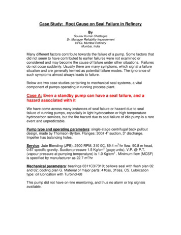
SEAL 750760METALRUBBERTEFLONLEATHERFELT7803
SEAL SPECIFICATION GUIDESEAL DESIGN TYPES NLEATHERFELT
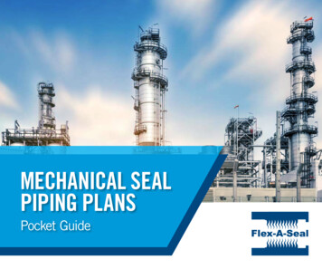
SHAFT RECOMMENDATIONSShaftsRecommended Shaft ChamferSeal and shaft compatibility is dependent on four conditions:shaft tolerance, lead-in chamfer, finish and hardness. Properconsideration of these conditions will assist in providingoptimal seal performance. SHAFT HARDNESS is an important factor to preventexcessive wear, deformation, scratches or nicks, and toallow for easy machining for proper roughness. Undernormal conditions, the seal contact area of the shaftshould be Rockwell C45 minimum. SHAFT SURFACE ROUGHNESS is very important as thisgreatly influences the amount of lip wear. The recommended roughness is as follows:– Rotating 10 to 20 µ inch Ra (.25 µM to .50 µM Ra):RMAX 31-126 µ inch (0.8-3.2 µM)– Reciprocating 5 to 10 µ inch Ra (.13 µM to .25 µMRa)The method of achieving this finish should not beoverlooked. PLUNGE GRINDING is recommended for rotating shaftapplications. For reciprocating applications, centerlessgrinding is acceptable. Rotating shaft applications require asurface with no machine lead, as machine lead may actually pump fluid from under the seal lip. Also, hard chromeplating is suggested for any cast iron or stainless steelshafts for rotating applications and for steel shafts withreciprocating applications. A SHAFT CHAMFER is suggested to assist in the installation process. Without a proper chamfer, the seal lip may bedamaged or distorted resulting in a dislodged garterspring. SHAFT TOLERANCE recommendations for generalapplications are listed below. The tolerance range shouldbe decreased for high speed or pressure applications.Typically15 -25 Rounded-Burr FreeEdgeS.D.D1S.D.Up to 1.0001.001 to 2.0002.001 to 3.0003.001 to 4.000INCHESD1S.D.S.D. – .0944.001 to 5.000S.D. – .1405.001 to 5.000S.D. – .1666.001 to 5.000S.D. – .196–D1S.D. – .220S.D. – .260S.D. – .276–S.D.Up to 25.0025.01 to 50.0050.01 to 75.0075.01 to 100.00MILLIMETERSD1S.D.S.D. – 2.4 100.01 to 125.00S.D. – 3.6 125.01 to 150.00S.D. – 4.2 150.01 to 250.00S.D. – 5.0–D1S.D. – 5.6S.D. – 6.6S.D. – 7.0–Recommended Shaft ToleranceSHAFT DIAMETER (INCH)Up to 4.0004.001 to 6.0006.001 to 10.000TOLERANCE .003 .004 .005SHAFT DIAMETER (DIN/METRIC)Up to 100 mm100.10 to 150.00150.10 to 250.00TOLERANCE 0.08 0.10 0.135
SEAL SPECIFICATION GUIDEHOUSING RECOMMENDATIONSHousingSteel and cast iron provide good surfaces for both rubbercovered and metal O.D. seals. For soft alloy (aluminum)bores, rubber covered O.D. seals provide better sealingcapability. In aluminum or other soft alloy bores, metal O.D.seals occasionally back out of the bore due to thermal expansion of the soft alloy. Rubber, having a higher coefficient ofthermal expansion than carbon steel, will tighten in the boresas temperature rises.Recommended Bore Chamfer0.005 Max. R.15/30 Deg.0.06/0.09This corner mustbe burr freePlastic or nylon are not recommended because they typicallyexpand at a high rate causing a major problem for metal O.D.seals. If plastic is to be used, rubber O.D. seals are recommended.Bore ChamferA bore chamfer is necessary to assist in installation of theseal. To the right is the recommended configuration for thechamfer.Surface RoughnessProper chamfer angle and depth minimizes cocking or lackof squareness of the seal to the shaft, distortion of the sealcases, and reduces assembly force.Excessively rough bore finishes may allow paths for fluidto leak between seal O.D. and bore. Below shows therecommended maximum roughness.MAXIMUMROUGHNESSMETAL O.D.100 µinch Ra2.50 µM RaRUBBER O.D.150 µinch Ra3.75 µM Ra492 µinch RMAX12.5 µM RMAXThe rubber O.D. seal is capable of functioning with a rougherfinish.MINIMUMROUGHNESSMETAL O.D.NoneNoneRUBBER O.D.60 µinch Ra1.5 µM RaA minimum bore roughness is recommended for rubber O.D.seals. This improves retention.6
BORE RECOMMENDATIONSBore Diameter ToleranceThe recommended housing bore diameter, boretolerance and nominal pressfit.INCH SIZESNORMAL PRESS FITSEALS WITH SEALS WITHMETAL O.D. RUBBER O.D.BOREDIAMETERBORETOLERANCEUp to 1.0001.001 - 2.0002.001 - 3.0003.001 - 4.0004.001 - 6.000 .001 .001 .001 .0015 .0015.004.004.004.005.0056.001 - 8.000 .002.0068.001 - 9.000 .002.0079.001 - 10.000 .002.008.006.006.006.008.010O.D. TOLERANCE (1)SEALS WITH SEALS WITHMETAL O.D. RUBBER O.D. .002 .002 .002 .002 .003–.002 .003–.002 .004–.002 .004–.002 .003 .003 .003 .004 .004OUT OF ROUND (2)SEALS WITH SEALS WITHMETAL O.D. RUBBER 5.015EQUIVALENT METRIC SIZESNORMAL PRESS FITSEALS WITH SEALS WITHMETAL O.D. RUBBER O.D.BOREDIAMETERBORETOLERANCEUp to 25.0025.01 - 50.0050.01 - 75.0075.01 - 100.00100.01 - 150.00 0.025 0.025 0.025 0.038 0.0380.100.100.100.130.13150.01 - 200.00 0.0510.15200.01 - 225.00 0.0510.18225.01 - 250.00 0.0510.200.150.150.150.200.25O.D. TOLERANCE (1)SEALS WITH SEALS WITHMETAL O.D. RUBBER O.D. 0.05 0.05 0.05 0.05 0.08–0.05 0.08–0.05 0.10–0.05 0.10–0.05 0.08 0.08 0.08 0.10 0.10OUT OF ROUND (2)SEALS WITH SEALS WITHMETAL O.D. RUBBER 380.38(1) Seal O.D. - The average of a minimum three measurements to betaken at equally spaced positions.(2) Out of Round (OOR) - The maximum variance between any of thereadings used in determining seal O.D.7
SEAL SPECIFICATION GUIDEOPERATING CONDITIONSSeal with SpringDESIGN LIMITATIONSSHAFTDIAMETERNITRILE LIP MAXIMUMCONTINUOUS SHAFT SPEEDMAXIMUM CONTINUOUSPRESSUREMAXIMUM TOTALECCENTRICITYGeneral3,500 rpm5 psi.020”.5007,000 rpm5 psi.004”1.5006,000 rpm5 psi.006”2.5004,000 rpm5 psi.010”3.5003,500 rpm5 psi.013”4.5002,600 rpm5 psi.017”NOTE: Higher shaft speed is possible using higher temperature materials such as polyacrylate, fluoroelastomeror silicone. Slightly higher continuous pressure is possible for shaft speeds below 200 fpm. Higher eccentricityis allowable if shaft speed is reduced.Seal without SpringDESIGN LIMITATIONSSHAFTDIAMETERMAXIMUMSHAFT SPEEDMAXIMUM CONTINUOUSPRESSUREGeneral2,000 rpm4 psi.005”.5003,500 rpm4 psi.003”1.5002,500 rpm4 psi.005”2.5002,100 rpm4 psi.006”3.5001,500 rpm4 psi.008”4.5001,200 rpm4 psi.010”NOTE: Higher eccentricity is allowable if maximum shaft speed is reduced.A nonsprung seal design offers a cost effective way to sealhigh viscosity grease applications. Because the design doesnot benefit from the constant load of a garter spring, theallowable eccentricity is decreased and the fluids to besealed are limited.8MAXIMUM TOTALECCENTRICITY pa
TIMKEN A LEADER IN SEAL TECHNOLOGY US 10 SEAL SPECIFICSEAL SPECIFICATION GUIDEATION GUIDE. HOW TO USE THIS CATALOG The seals listed in this catalog are arranged by shaft size and part number. Determine the method you will use for your search, then turn to the corresponding section found in the table of contents. Each seal will have the dimensions, along with the seal