Transcription
Arduino Mega 2560 Datasheet
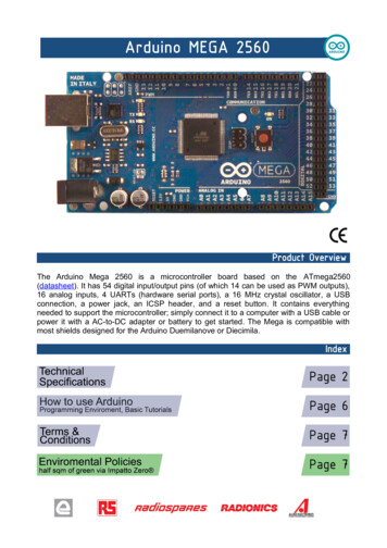
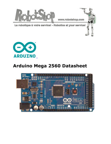
OverviewThe Arduino Mega 2560 is a microcontroller board based on the ATmega2560 (datasheet).It has 54 digital input/output pins (of which 14 can be used as PWM outputs), 16 analoginputs, 4 UARTs (hardware serial ports), a 16 MHz crystal oscillator, a USB connection, apower jack, an ICSP header, and a reset button. It contains everything needed to supportthe microcontroller; simply connect it to a computer with a USB cable or power it with a ACto-DC adapter or battery to get started. The Mega is compatible with most shields designedfor the Arduino Duemilanove or Diecimila.Schematic & Reference DesignEAGLE files: arduino-mega2560-reference-design.zip
Schematic: erOperating VoltageInput Voltage (recommended)Input Voltage (limits)Digital I/O PinsAnalog Input PinsDC Current per I/O PinDC Current for 3.3V PinFlash MemorySRAMEEPROMClock SpeedATmega25605V7-12V6-20V54 (of which 14 provide PWM output)1640 mA50 mA256 KB of which 8 KB used by bootloader8 KB4 KB16 MHzPowerThe Arduino Mega can be powered via the USB connection or with an external power supply.The power source is selected automatically.External (non-USB) power can come either from an AC-to-DC adapter (wall-wart) orbattery. The adapter can be connected by plugging a 2.1mm center-positive plug into theboard's power jack. Leads from a battery can be inserted in the Gnd and Vin pin headers ofthe POWER connector.The board can operate on an external supply of 6 to 20 volts. If supplied with less than7V, however, the 5V pin may supply less than five volts and the board may be unstable.If using more than 12V, the voltage regulator may overheat and damage the board. Therecommended range is 7 to 12 volts.The Mega2560 differs from all preceding boards in that it does not use the FTDI USB-toserial driver chip. Instead, it features the Atmega8U2 programmed as a USB-to-serialconverter.
The power pins are as follows: VIN. The input voltage to the Arduino board when it's using an external power source(as opposed to 5 volts from the USB connection or other regulated power source). Youcan supply voltage through this pin, or, if supplying voltage via the power jack, accessit through this pin.5V. The regulated power supply used to power the microcontroller and othercomponents on the board. This can come either from VIN via an on-board regulator,or be supplied by USB or another regulated 5V supply.3V3. A 3.3 volt supply generated by the on-board regulator. Maximum current draw is50 mA.GND. Ground pins.MemoryThe ATmega2560 has 256 KB of flash memory for storing code (of which 8 KB is used forthe bootloader), 8 KB of SRAM and 4 KB of EEPROM (which can be read and written with theEEPROM library).Input and OutputEach of the 54 digital pins on the Mega can be used as an input or output, using pinMode(), digitalWrite(), and digitalRead() functions. They operate at 5 volts. Each pin can provide orreceive a maximum of 40 mA and has an internal pull-up resistor (disconnected by default)of 20-50 kOhms. In addition, some pins have specialized functions: Serial: 0 (RX) and 1 (TX); Serial 1: 19 (RX) and 18 (TX); Serial 2: 17 (RX)and 16 (TX); Serial 3: 15 (RX) and 14 (TX). Used to receive (RX) and transmit(TX) TTL serial data. Pins 0 and 1 are also connected to the corresponding pins of theATmega8U2 USB-to-TTL Serial chip.External Interrupts: 2 (interrupt 0), 3 (interrupt 1), 18 (interrupt 5),19 (interrupt 4), 20 (interrupt 3), and 21 (interrupt 2). These pins can beconfigured to trigger an interrupt on a low value, a rising or falling edge, or a changein value. See the attachInterrupt() function for details.PWM: 0 to 13. Provide 8-bit PWM output with the analogWrite() function.SPI: 50 (MISO), 51 (MOSI), 52 (SCK), 53 (SS). These pins support SPIcommunication using the SPI library. The SPI pins are also broken out on the ICSPheader, which is physically compatible with the Uno, Duemilanove and Diecimila.LED: 13. There is a built-in LED connected to digital pin 13. When the pin is HIGH
value, the LED is on, when the pin is LOW, it's off.I2C: 20 (SDA) and 21 (SCL). Support I2C (TWI) communication using the Wirelibrary (documentation on the Wiring website). Note that these pins are not in thesame location as the I2C pins on the Duemilanove or Diecimila.The Mega2560 has 16 analog inputs, each of which provide 10 bits of resolution (i.e. 1024different values). By default they measure from ground to 5 volts, though is it possible tochange the upper end of their range using the AREF pin and analogReference() function.There are a couple of other pins on the board: AREF. Reference voltage for the analog inputs. Used with analogReference().Reset. Bring this line LOW to reset the microcontroller. Typically used to add a resetbutton to shields which block the one on the board.CommunicationThe Arduino Mega2560 has a number of facilities for communicating with a computer,another Arduino, or other microcontrollers. The ATmega2560 provides four hardware UARTsfor TTL (5V) serial communication. An ATmega8U2 on the board channels one of theseover USB and provides a virtual com port to software on the computer (Windows machineswill need a .inf file, but OSX and Linux machines will recognize the board as a COM portautomatically. The Arduino software includes a serial monitor which allows simple textualdata to be sent to and from the board. The RX and TX LEDs on the board will flash whendata is being transmitted via the ATmega8U2 chip and USB connection to the computer (butnot for serial communication on pins 0 and 1).A SoftwareSerial library allows for serial communication on any of the Mega2560's digitalpins.The ATmega2560 also supports I2C (TWI) and SPI communication. The Arduino softwareincludes a Wire library to simplify use of the I2C bus; see the documentation on the Wiringwebsite for details. For SPI communication, use the SPI library.ProgrammingThe Arduino Mega can be programmed with the Arduino software (download). For details,see the reference and tutorials.The ATmega2560 on the Arduino Mega comes preburned with a bootloader that allowsyou to upload new code to it without the use of an external hardware programmer. It
communicates using the original STK500 protocol (reference, C header files).You can also bypass the bootloader and program the microcontroller through the ICSP (InCircuit Serial Programming) header; see these instructions for details.Automatic (Software) ResetRather then requiring a physical press of the reset button before an upload, the ArduinoMega2560 is designed in a way that allows it to be reset by software running on aconnected computer. One of the hardware flow control lines (DTR) of the ATmega8U2 isconnected to the reset line of the ATmega2560 via a 100 nanofarad capacitor. When thisline is asserted (taken low), the reset line drops long enough to reset the chip. The Arduinosoftware uses this capability to allow you to upload code by simply pressing the uploadbutton in the Arduino environment. This means that the bootloader can have a shortertimeout, as the lowering of DTR can be well-coordinated with the start of the upload.This setup has other implications. When the Mega2560 is connected to either a computerrunning Mac OS X or Linux, it resets each time a connection is made to it from software (viaUSB). For the following half-second or so, the bootloader is running on the Mega2560. Whileit is programmed to ignore malformed data (i.e. anything besides an upload of new code),it will intercept the first few bytes of data sent to the board after a connection is opened.If a sketch running on the board receives one-time configuration or other data when itfirst starts, make sure that the software with which it communicates waits a second afteropening the connection and before sending this data.The Mega2560 contains a trace that can be cut to disable the auto-reset. The pads on eitherside of the trace can be soldered together to re-enable it. It's labeled "RESET-EN". You mayalso be able to disable the auto-reset by connecting a 110 ohm resistor from 5V to the resetline; see this forum thread for details.USB Overcurrent ProtectionThe Arduino Mega2560 has a resettable polyfuse that protects your computer's USBports from shorts and overcurrent. Although most computers provide their own internalprotection, the fuse provides an extra layer of protection. If more than 500 mA is applied tothe USB port, the fuse will automatically break the connection until the short or overload isremoved.Physical Characteristics and ShieldCompatibility
The maximum length and width of the Mega2560 PCB are 4 and 2.1 inches respectively,with the USB connector and power jack extending beyond the former dimension. Threescrew holes allow the board to be attached to a surface or case. Note that the distancebetween digital pins 7 and 8 is 160 mil (0.16"), not an even multiple of the 100 mil spacingof the other pins.The Mega2560 is designed to be compatible with most shields designed for the Uno,Diecimila or Duemilanove. Digital pins 0 to 13 (and the adjacent AREF and GND pins),analog inputs 0 to 5, the power header, and ICSP header are all in equivalent locations.Further the main UART (serial port) is located on the same pins (0 and 1), as are externalinterrupts 0 and 1 (pins 2 and 3 respectively). SPI is available through the ICSP header onboth the Mega2560 and Duemilanove / Diecimila. Please note that I2C is not located on thesame pins on the Mega (20 and 21) as the Duemilanove / Diecimila (analog inputs 4 and 5).
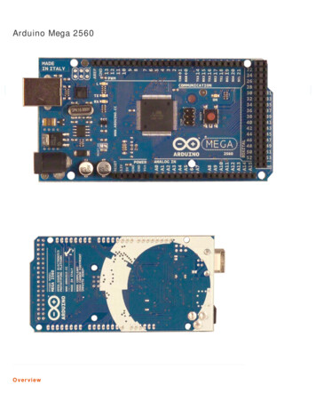
The Arduino Mega 2560 is a microcontroller board based on the ATmega2560 (datasheet). It has 54 digital input/output pins (of which 14 can be used as PWM outputs), 16 analog inputs, 4 UARTs (hardware serial ports), a 16 MHz crystal oscillator, a USB connection, a power jack, an ICSP header, and a reset button. It contains everything needed to support the microcontroller; simply connect it to a .