Transcription
Arduino Mega 2560Overview
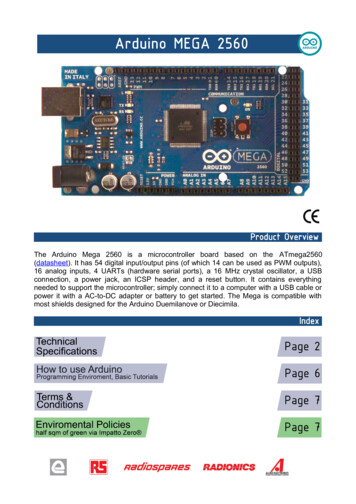
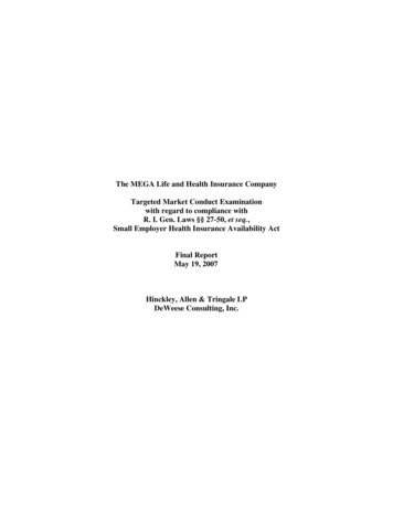
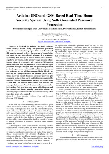
The Arduino Mega 2560 is a microcontroller board based on the ATmega2560 (datasheet). It has 54 digital input/outputpins (of which 14 can be used as PWM outputs), 16 analog inputs, 4 UARTs (hardware serial ports), a 16 MHz crystaloscillator, a USB connection, a power jack, an ICSP header, and a reset button. It contains everything needed to supportthe microcontroller; simply connect it to a computer with a USB cable or power it with a AC-to-DC adapter or battery toget started. The Mega is compatible with most shields designed for the Arduino Duemilanove or Diecimila.Schematic & Reference DesignEAGLE files: arduino-mega2560-reference-design.zipSchematic: erATmega2560Operating Voltage5VInput Voltage (recommended) 7-12VInput Voltage (limits)6-20VDigital I/O Pins54 (of which 14 provide PWM output)Analog Input Pins16DC Current per I/O Pin40 mADC Current for 3.3V Pin50 mAFlash Memory256 KB of which 8 KB used by bootloaderSRAM8 KBEEPROM4 KBClock Speed16 MHzPowerThe Arduino Mega can be powered via the USB connection or with an external power supply. The power source is selectedautomatically.External (non-USB) power can come either from an AC-to-DC adapter (wall-wart) or battery. The adapter can beconnected by plugging a 2.1mm center-positive plug into the board's power jack. Leads from a battery can be inserted inthe Gnd and Vin pin headers of the POWER connector.The board can operate on an external supply of 6 to 20 volts. If supplied with less than 7V, however, the 5V pin may supplyless than five volts and the board may be unstable. If using more than 12V, the voltage regulator may overheat and damagethe board. The recommended range is 7 to 12 volts.The Mega2560 differs from all preceding boards in that it does not use the FTDI USB-to-serial driver chip. Instead, itfeatures the Atmega8U2 programmed as a USB-to-serial converter.The power pins are as follows:
VIN. The input voltage to the Arduino board when it's using an external power source (as opposed to 5 volts from theUSB connection or other regulated power source). You can supply voltage through this pin, or, if supplying voltage viathe power jack, access it through this pin.5V. The regulated power supply used to power the microcontroller and other components on the board. This can comeeither from VIN via an on-board regulator, or be supplied by USB or another regulated 5V supply.3V3. A 3.3 volt supply generated by the on-board regulator. Maximum current draw is 50 mA.GND. Ground pins.MemoryThe ATmega2560 has 256 KB of flash memory for storing code (of which 8 KB is used for the bootloader), 8 KB of SRAMand 4 KB of EEPROM (which can be read and written with the EEPROM library).Input and OutputEach of the 54 digital pins on the Mega can be used as an input or output, using pinMode(), digitalWrite(), anddigitalRead() functions. They operate at 5 volts. Each pin can provide or receive a maximum of 40 mA and has an internalpull-up resistor (disconnected by default) of 20-50 kOhms. In addition, some pins have specialized functions:Serial: 0 (RX) and 1 (TX); Serial 1: 19 (RX) and 18 (TX); Serial 2: 17 (RX) and 16 (TX); Serial 3: 15(RX) and 14 (TX). Used to receive (RX) and transmit (TX) TTL serial data. Pins 0 and 1 are also connected to thecorresponding pins of the ATmega8U2 USB-to-TTL Serial chip.External Interrupts: 2 (interrupt 0), 3 (interrupt 1), 18 (interrupt 5), 19 (interrupt 4), 20 (interrupt3), and 21 (interrupt 2). These pins can be configured to trigger an interrupt on a low value, a rising or falling edge,or a change in value. See the attachInterrupt() function for details.PWM: 0 to 13. Provide 8-bit PWM output with the analogWrite() function.SPI: 50 (MISO), 51 (MOSI), 52 (SCK), 53 (SS). These pins support SPI communication using the SPI library.The SPI pins are also broken out on the ICSP header, which is physically compatible with the Uno, Duemilanove andDiecimila.LED: 13. There is a built-in LED connected to digital pin 13. When the pin is HIGH value, the LED is on, when thepin is LOW, it's off.I 2 C: 20 (SDA) and 21 (SCL). Support I 2C (TWI) communication using the Wire library (documentation on theWiring website). Note that these pins are not in the same location as the I 2C pins on the Duemilanove or Diecimila.The Mega2560 has 16 analog inputs, each of which provide 10 bits of resolution (i.e. 1024 different values). By default theymeasure from ground to 5 volts, though is it possible to change the upper end of their range using the AREF pin andanalogReference() function.
There are a couple of other pins on the board:AREF. Reference voltage for the analog inputs. Used with analogReference().Reset. Bring this line LOW to reset the microcontroller. Typically used to add a reset button to shields which blockthe one on the board.CommunicationThe Arduino Mega2560 has a number of facilities for communicating with a computer, another Arduino, or othermicrocontrollers. The ATmega2560 provides four hardware UARTs for TTL (5V) serial communication. An ATmega8U2on the board channels one of these over USB and provides a virtual com port to software on the computer (Windowsmachines will need a .inf file, but OSX and Linux machines will recognize the board as a COM port automatically. TheArduino software includes a serial monitor which allows simple textual data to be sent to and from the board. The RX andTX LEDs on the board will flash when data is being transmitted via the ATmega8U2 chip and USB connection to thecomputer (but not for serial communication on pins 0 and 1).A SoftwareSerial library allows for serial communication on any of the Mega2560's digital pins.The ATmega2560 also supports I2C (TWI) and SPI communication. The Arduino software includes a Wire library tosimplify use of the I2C bus; see the documentation on the Wiring website for details. For SPI communication, use the SPIlibrary.ProgrammingThe Arduino Mega can be programmed with the Arduino software (download). For details, see the reference and tutorials.The ATmega2560 on the Arduino Mega comes preburned with a bootloader that allows you to upload new code to itwithout the use of an external hardware programmer. It communicates using the original STK500 protocol (reference, Cheader files).You can also bypass the bootloader and program the microcontroller through the ICSP (In-Circuit Serial Programming)header; see these instructions for details.The ATmega8U2 firmware source code is available in the Arduino repository. The ATmega8U2 is loaded with a DFUbootloader, which can be activated by connecting the solder jumper on the back of the board (near the map of Italy) andthen resetting the 8U2. You can then use Atmel's FLIP software (Windows) or the DFU programmer (Mac OS X andLinux) to load a new firmware. Or you can use the ISP header with an external programmer (overwriting the DFUbootloader). See this user-contributed tutorial for more information.Automatic (Software) ResetRather then requiring a physical press of the reset button before an upload, the Arduino Mega2560 is designed in a waythat allows it to be reset by software running on a connected computer. One of the hardware flow control lines (DTR) ofthe ATmega8U2 is connected to the reset line of the ATmega2560 via a 100 nanofarad capacitor. When this line isasserted (taken low), the reset line drops long enough to reset the chip. The Arduino software uses this capability to allowyou to upload code by simply pressing the upload button in the Arduino environment. This means that the bootloader can
have a shorter timeout, as the lowering of DTR can be well-coordinated with the start of the upload.This setup has other implications. When the Mega2560 is connected to either a computer running Mac OS X or Linux, itresets each time a connection is made to it from software (via USB). For the following half-second or so, the bootloader isrunning on the Mega2560. While it is programmed to ignore malformed data (i.e. anything besides an upload of newcode), it will intercept the first few bytes of data sent to the board after a connection is opened. If a sketch running on theboard receives one-time configuration or other data when it first starts, make sure that the software with which itcommunicates waits a second after opening the connection and before sending this data.The Mega2560 contains a trace that can be cut to disable the auto-reset. The pads on either side of the trace can besoldered together to re-enable it. It's labeled "RESET-EN". You may also be able to disable the auto-reset by connecting a110 ohm resistor from 5V to the reset line; see this forum thread for details.USB Overcurrent ProtectionThe Arduino Mega2560 has a resettable polyfuse that protects your computer's USB ports from shorts and overcurrent.Although most computers provide their own internal protection, the fuse provides an extra layer of protection. If morethan 500 mA is applied to the USB port, the fuse will automatically break the connection until the short or overload isremoved.Physical Characteristics and Shield CompatibilityThe maximum length and width of the Mega2560 PCB are 4 and 2.1 inches respectively, with the USB connector andpower jack extending beyond the former dimension. Three screw holes allow the board to be attached to a surface or case.Note that the distance between digital pins 7 and 8 is 160 mil (0.16"), not an even multiple of the 100 mil spacing of theother pins.The Mega2560 is designed to be compatible with most shields designed for the Uno, Diecimila or Duemilanove. Digitalpins 0 to 13 (and the adjacent AREF and GND pins), analog inputs 0 to 5, the power header, and ICSP header are all inequivalent locations. Further the main UART (serial port) is located on the same pins (0 and 1), as are external interrupts0 and 1 (pins 2 and 3 respectively). SPI is available through the ICSP header on both the Mega2560 and Duemilanove /Diecimila. Please note that I 2C is not located on the same pins on the Mega (20 and 21) as the Duemilanove / Diecimila(analog inputs 4 and 5).
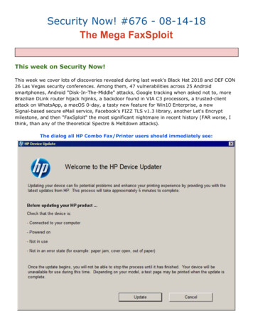
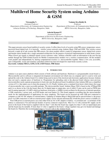
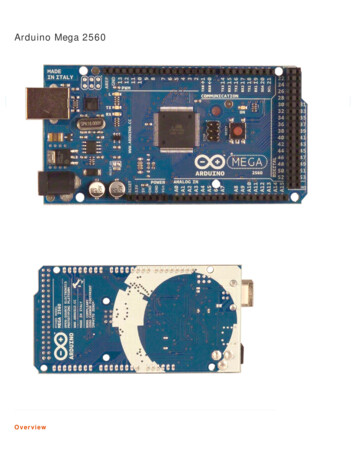
Arduino Mega 2560 Reference DesignTMReference Designs ARE PROVIDED "AS IS" AND "WITH ALL FAULTS". Arduino DISCLAIMS ALL OTHER WARRANTIES, EXPRESS OR IMPLIED,REGARDING PRODUCTS, INCLUDING BUT NOT LIMITED TO, ANY IMPLIED WARRANTIES OF MERCHANTABILITY OR FITNESS FOR A PARTICULAR PURPOSEArduino may make changes to specifications and product descriptions at any time, without notice. The Customer must notrely on the absence or characteristics of any features or instructions marked "reserved" or "undefined." Arduino reservesthese for future definition and shall have no responsibility whatsoever for conflicts or incompatibilities arising from future changes to them.The product information on the Web Site or Materials is subject to change without notice. Do not finalize a design with this information. DC88283848586878889 5V GND2116MHzQ22116MHzQ1MOSI22COMMUNICATION7RN2B 22R312346RN2C 22RUSBVCC22R8 RN2A1500mADD 22R5 RN2D418R2RD- 1MRD 274XT116MHz 5VGND5322731302928EXP12120191817 MISO216 MOSI215 2(PC0)XTAL1AVCCUCAPUVCCDD ND131211TXL10RXL9 M8RXD8 PE17RN4B 1k37C11100nGNDCMP 3V356372LM358DIC5A1LM358DGNDC12100nGNDIC5BGATE CMD 5VUSBVCC 5V 5V 132T2FDN340PINOUT5ENGND NC/FB4 3V3 3V3GNDGNDRESETGND36RN4C 1kTXYELLOW4M8RXDM8TXD18RN4A 1kVIN2ATMEGA8U2-MU2GND5RN1D 10K 5VDTRGROUNDRN5D 10K42XT1R 1VUCAPUSBVCCRDRD UGND1uC10100nC9RN3B 1kADCLXT243L1RN3A 5 pwmPG2PG1PG0C1522pC1622pGNDC1722p6RN1C 3SCK2RESET2 SP12VINTXD3RXD3GND4241403938373635pwmpwm 5V1312111098C75250484644424038PH6PH5GND100n(SCK) PB1(MISO) 0282624228PB0 (SS)PB2 3222120192468101214161XT1USB boot 5JP310K8 RN5A1100nVCCVCCVCCVCCGNDGNDGNDGNDXIOHJP21100n 1010604C59810099PA7PA6PA5PA4PA3PA2PA1PA0Z2C4 5VXTAL27172737475767778PGB1
The Arduino Mega 2560 is a microcontroller board based on the ATmega2560 (datasheet). It has 54 digital input/output pins (of which 14 can be used as PWM outputs), 16 analog inputs, 4 UARTs (hardware serial ports), a 16 MHz crystal oscillator, a USB connection, a power jack, an ICSP header, and a reset button. It contains everything needed to .