Transcription
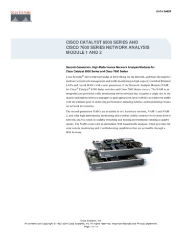
LS Series Crate Engine Control System Ensure the fuel pump has the following flow capability: Minimum40 gph @ 400 kPa for LS2/LS3/LS376s and Minimum 50 gph @400 kPa for the LSX454 & LS7s.Thank you for choosing Chevrolet Performance as your high Ensure battery voltage is connected using a minimum 8 gauge wire toperformance source. Chevrolet Performance is committed to providingone of the studs on the fuse block.proven, innovative performance technology that is truly. more than justpower. Chevrolet Performance parts are engineered, developed and Ensure that the accelerator pedal clearances meet the guidelinestested to exceed your expectations for fit and function. Please refer tobelow.our catalog for the Chevrolet Performance Authorized Center nearestDon’t:you or visit our website at www.chevyperformance.com. Change or alter any wiring in the accelerator pedal or electronicThis control system is a stand alone, fully-integrated kit designed tothrottle systems.run Chevrolet Performance Parts LS Series crate engines with 58xcrankshaft reluctor wheels, 4x camshaft indexing, and electronic throttle Vacuum reference the fuel system, it must run constant400 kPa (60 psi).control (ETC) - typically 2006 and newer. Included in the kit are theengine control module (flashed with the appropriate calibration), engine Solder or alter any Oxygen Sensor wiring.harness, accelerator pedal, mass air flow (MAF) sensor, MAF sensorVehicle Requirementsmounting boss, oxygen sensors (2), and oxygen sensor mountingVehicle Speed Input - optionalbosses (2). This control system requires a fuel system which maintainsThe ECM is programmed and looking for 40 pulses per revolution400 kPa (60 psi) constant pressure and can deliver 40 gph for thetypical for automatic transmissions. The LS Control System harnessLS2/LS3/LS376s or 50 gph for LSX454 & LS7s. Vehicle performance/is designed to plug into the output speed sensor of 4L60 & 4L80driveability and engine durability may be affected if the correct pressureTransmissions, which have a 40 pulse output. NOTE: If you are usingor flow are not maintained.the CP Supermatic Connect and Cruise Transmission ControlIMPORTANT: Read the “System DOs and DON’Ts” section belowSystem, the vehicle speed input must be plugged in.before attempting to install the engine and then review againAxle Ratio and Tire Size Requirementsbefore attempting start the vehicle. Note that if the engine willThe axle drive ratio in the calibration is set to 3.42:1 and is okay fornot come off idle after the control system installation, check forratio from 3.08 to 4.11. Tire diameter needs to be between 26” and 30”.an illuminated MIL (malfunction indicator light, which is locatedNOTE: For optimal performance choose an axle ratio and a tire sizein the fuse/relay center, sometimes called the “Check EngineLight” or “Service Engine Soon” light) which indicates stored fault within the recommended range.codes. Check for codes and make any required repairs if the MILNOTE: All Engines are shipped with an automatic transmission flexis illuminated (typically it is a connector issue or a wiring issue),plate. For manual applications, the clutch and flywheel used must beconsult a service manual if necessary (Use information frompurchased separately and is up to the end user.Chevrolet Performance Parts Diagnostics, 2006- 2011 Cadillac CTS, See www.chevyperformance.com for recommended CP clutches and2006 – 2010 Corvette or 2010-2011 Camaro).flywheels.Observe all safety precautions and warnings in the servicemanuals when installing this package in any vehicle. Wear eyeprotection and appropriate protective clothing. Support the vehiclesecurely with jack stands when working under or around it. Useonly the proper tools. Exercise extreme caution when working withflammable, corrosive, and hazardous liquids and materials. Someprocedures require special equipment and skills. If you do not havethe appropriate training, expertise, and tools to perform any part ofthis conversion safely, this work should be done by a professional.System DOs and DON’Ts:Do: Ensure all intended engine/vehicle side connections are made beforeconnecting ignition or battery power to the system. Ensure the wiring harness is secured as required, and that the routingavoids locations which can potentially damage the wiring (e.g.: sharpedges, pinch points, rotating components, exhaust components, etc.).Make sure any unused connectors or wiring are properly secured andprotected (sealed or taped as required to avoid short circuiting).Also see the CP Catalog or www.chevyperformance.com forrecommended starter, flywheel and clutch components.NOTE: The parts listed here may have been updated orsuperseded, go to www.chevyperformance.com for the latest partnumber list.Parts List:These instructions cover the following packages:19354334LS7 Engine Control System Kit19354328LS2 Engine Control System Kit - same as LS319354330LS376-480 Engine Control System Kit19354332LS376-525 Engine Control System Kit19354328LS3 Engine Control System Kit19354342LSX454 Engine Control System Kit for Auto Trans19354344LSX454 Engine Control System Kit for Manual TransFor LS2 applications, please see last page. Ensure all engine and wiring harness grounds are clean and secure.Minimum ¾ inch braided strap from the engine to the vehicle chassisis recommended.Each Kit will contain an Engine Control Unit pre-programmed for thespecific engine kit.All Engine Control Kits have the following parts:19171935I-Sheet (Instruction Sheet)19166573Engine Harness19202597MAP Sensor Jumper LS3/LS376-or- 19202598 LS2/LS7/LSX454 Ensure the MAF Sensor is mounted in the middle of a minimum 6 inch15865791Mass Airflow Sensorlength of 4 inch diameter tube, and is a minimum of 10 inches from19166574Mass Airflow Sensor Bracketthe throttle body.10379038Accelerator Pedal Ensure the fuel pressure is a constant 400 kPa (60 psi) with the engine12581966Oxygen Sensor - Quantity 2running. This is what the control system has been developed to run.15156588Oxygen Sensor mounting boss – Quantity 2 Ensure the MAF sensor is oriented correctly in the induction (it willonly read correctly in the proper direction). An arrow is located on thesensor indicating correct flow direction. Verify this before welding themounting boss, as the sensor will mount only one way in the boss.TITLELS Series Crate Engine Control SystemREV 19MY16ALL INFORMATION WITHIN ABOVE BORDER TO BE PRINTED EXACTLY AS SHOWN ON 8 1/2 x 11WHITE 16 POUND BOND PAPER. PRINT ON BOTH SIDES, EXCLUDING TEMPLATES.TO BE UNITIZED IN ACCORDANCE WITH GM SPECIFICATIONS.DATEPART NO.19171935REVISIONSHEET1OF24AUTH
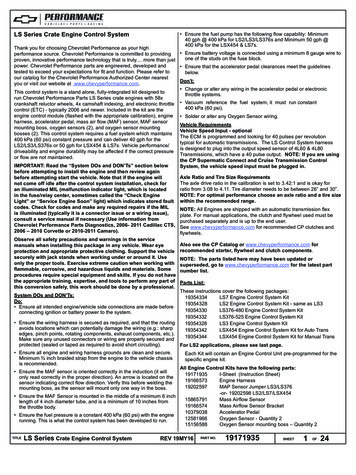
Installation Instructions:Air Cleaner: It is recommended that a dry element air cleaner be used.NOTE: Fueling cannot be guaranteed if an oiled element type aircleaner is used.ECMThe Engine Control Module (ECM) is environmentally sealed and can bemounted underhood, however, avoid extremely hot locations (exhaust,Oxygen Sensors: NOTE: It is critical that the Oxygen Sensors areetc.) or high splash areas. It is not recommended that the EMC bemounted per the instructions below. The exhaust system MUST bemounted directly to the engine.properly sealed – any leak near the sensors (upstream or downstream) can cause incorrect operation of the fuel control system.Accelerator PedalVehicle performance and/or driveability may be affected if sensorsMount the accelerator pedal per the following dimensional guidelines,are not mounted as recommended or if an exhaust leak exists. Leakmounting details are application-specific and are left to the user. Ensure check the exhaust system to ensure adequate sealing (even smallthat the pedal is securely mounted to the vehicle. A grommet is required leaks can affect fuel control).in any sheet metal hole that the harness routes through to avoid wireOxygen Sensors should be mounted in the collector area of the exdamage.haust manifolds in a location that allows exhaust from all cylinders toACCELERATOR PEDAL ASSEMBLY MINIMUM SPACING GUIDELINESbe sampled equally (stock exhaust manifolds include a mounting bossfor the oxygen sensors). Be sure the connectors and wiring are routed2.5”away from high heat areas. The oxygen sensors should be mountedwith the sensor tip pointing between horizontal and fully downward – do2”not mount with the tip oriented upward. Weld in the mounting bossesBrake Pedal Brakesupplied (7/8” hole) if using headers.PedalAcceleratorPedalExhaust Manifolds: It is recommended that you use the provided exhaust manifolds or similar LS Engine style Exhaust Manifolds.75”AcceleratorPedalPositive Crankcase Ventilation System (PCV)How to set up your PCV system:There are two ports on the engine that make up the PCV system. Theports on the engine are:Tunnel /ConsoleFront ViewSide ViewMass Air Flow (MAF) SensorNOTE: It is critical that the MAF sensor is mounted per theinstructions below. Vehicle performance and/or driveability may beaffected if it is not mounted as recommended.1) Left rear (driver side) valve cover.Weld the boss in place before installing the sensor. When installed inthe vehicle, the MAF sensor should be mounted with the connector endpointing between horizontal and fully upright – do not mount with theconnector oriented downward.Power Brake Booster Vacuum Source: The vacuum port for the BrakeBooster is a plug in the rear of the intake manifold. If you need thevacuum source for your brake system the plug needs to be removed andyou will need fitting #12559760 available from any GM dealer.2) Top center of the inlet manifold.The ports with silver tubes may look simple but, they should not bemodified. The tubes have a small orifice within them that is used inThe mass air flow sensor must be installed in the induction system using place of a PCV valve of earlier designs.the supplied MAF sensor mounting boss. The induction system shouldbe 4 inches in diameter and have a minimum straight section 6 inchesThere is one fresh air port which is on the front of the right (passengerin length. Mount the MAF sensor in the middle of the straight inductionside) valve cover. Again this is a silver tube that faces forward on thesection, ensuring that the middle of the mounting boss is at leastvalve cover. This port should be connected to filtered clean air. This10 inches from the throttle body.connection must be within the engines air cleaner system and must beThe MAF sensor must be oriented correctly in the inductionbetween the MAF (Mass Air Flow Sensor) and engine’s throttle body.system – note the arrow on the sensor indicating flow direction.The engine burns the air that enters the PCV system so, if the fresh airBe sure to weld the mounting boss correctly – the sensor will only port is prior to the MAF then, this air will enter the engine without beingmount one way in the boss (see diagram).measured by the MAF and adverse engine operation may occur.Oil Pressure Sensor: If your harness connector does not fit your oilpressure sensor you can purchase sensor p/n 12616646 or equivalent.This is an optional connection and is not required for your control systemto operate.MAF SENSOR MOUNTING GUIDELINESMINIMUM 6” STRAIGHT SECTION4”TO AIR FILTERTUBEMAF SENSOR MOUNTING BOSSnsorMounti ngeaMASeArFMINIMUM 10” FROM THROTTLE BODYEngine Wiring Harness: The following lists the engine and vehicleside connections. Optional circuits are described in the ‘SystemFeatures’ section below: NOTE: A Malfunction Indicator Lamp (MILsometimes called a “service engine soon” light) is mounted insidethe fuse/relay center. A redundant MIL output is also available inthe harness near the pedal module connector. It is recommendedthat a MIL also be installed in a visible location in the passengercompartment. This circuit requires any 12v low current light andan ignition 12v power source. The ECM MIL output supplies theground for the circuit.UPTITLELS Series Crate Engine Control SystemREV 19MY16ALL INFORMATION WITHIN ABOVE BORDER TO BE PRINTED EXACTLY AS SHOWN ON 8 1/2 x 11WHITE 16 POUND BOND PAPER. PRINT ON BOTH SIDES, EXCLUDING TEMPLATES.TO BE UNITIZED IN ACCORDANCE WITH GM SPECIFICATIONS.DATEPART NO.19171935REVISIONSHEET2OF24AUTH
Connections Required for Correct Operation Coolant Sensor – 2 pin Connector Mass Air Flow (MAF) Sensor – 5 pin Connector Camshaft Position Sensor – 3 pin Connector Electronic Throttle Control – 6 pin Connector Manifold Absolute Pressure (MAP) Sensor – 3 pin Connector Oxygen Sensors (2 total) – 5 pin Connectors Knock Sensors (2 total) – 2 pin Connectors Ignition Coil Blocks (2 total) – 8 pin Connectors Fuel Injectors (8 total) – 2 pin Connectors Crankshaft Position Sensor – 3 pin Connector Accelerator Pedal Sensor – 6 pin Connector Ignition Switch Input (Wire) Wire Fuel Pump Control (Wire) Wire Engine Grounds (3 total) Eyelets Battery Power (Stud at Fuse/Relay Center)Cooling Fan Control WireAttach a 12 volt ignition switch feed from the vehicle to the pink ignitionswitch wire in the harness (this is required to enable the proper powerup sequence of the ECM). This can be routed into the passengercompartment with the accelerator pedal connector and diagnosticlink connector. Next, connect battery power (minimum 8 gauge wire)to the horizontal stud on the fuse relay center The other two studs arefor accessories and are 50 amp fused), and the harness installation iscomplete.Additional features and bulkhead connector descriptions are alsoincluded below:System Features The Fuse/Relay center contains all required fuses and relays forproper engine operation. Spare fuse and relay openings are providedfor possible future customer use. The Fuse/Relay center includes a malfunction indicator light (MIL)which will illuminate in the event of an engine fault code. See yourChevrolet Performance Parts dealer to have this code retrieved at thediagnostic link connector in the fuse/relay center (using a Tech2 withChevrolet Performance Parts Diagnostics selection or 2009 CTS LSAManual Trans Configur
Change or alter any wiring in the accelerator pedal or electronic throttle systems. Vacuum reference the fuel system, it must run constant 400 kPa (60 psi). Solder or alter any Oxygen Sensor wiring. Vehicle Requirements Vehicle Speed Input - optional The ECM is