Transcription
1SOFTWARE ENGINEERINGNetworks andCommunicationDepartmentLecture 6By: Latifa ALrashed
Outlineq Define the concept of the software life cycle in software engineering.q Identify the system development life cycle (SDLC).q q q q q q Describe two major types of development process, the waterfall andincremental models.Discuss the analysis phase and describe two separate approaches in theanalysis phase: procedure-oriented analysis and object-oriented analysis.Discuss the design phase and describe two separate approaches in thedesign phase: procedure-oriented design and object-oriented design.Describe the implementation phase and recognize the quality issues in thisphase.Describe the testing phase and distinguish between glass-box testing andblackbox testing.Show the importance of documentation in software engineering anddistinguish between user documentation, system documentation andtechnical documentation.Networks and Communication Department
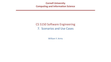
The software lifecycle A fundamental concept in software engineering is thesoftware lifecycle.Software, like many other products, goes through acycle of repeating phases.Networks and Communication DepartmentFigure 10.1 The software lifecycle
The software lifecycle (Cont.) Software is first developed by a group of developers.Usually it is in use for a while before modifications arenecessary.The two steps, use and modify, continue until thesoftware becomes obsolete.By “obsolete”, we mean that the software loses itsvalidity because of inefficiency, obsolescence of thelanguage, major changes in user requirements, or otherfactors.Networks and Communication Department
Developing Information Systems System Development Methodology is a standardprocess followed in an organization to conduct allthe steps necessary to analyze, design, implement,and maintain information systems.Networks and Communication Department
Systems Development Life Cycle (SDLC) Traditional methodology used to develop, maintain,and replace information systems.Phases in SDLC:Planning Analysis Design Implementation Maintenance FIGUREThe systems development life cycleNetworks and Communication Department
Systems Development Life Cycle (SDLC)(Cont.) Planning – an organization’s total informationsystem needs are identified, analyzed, prioritized,and arrangedAnalysis – system requirements are studied andstructuredDesign – a description of the recommendedsolution is converted into logical and then physicalsystem specificationsNetworks and Communication Department
Systems Development Life Cycle (SDLC)(Cont.) Logical design – all functional features of the systemchosen for development in analysis are describedindependently of any computer platformPhysical design – the logical specifications of thesystem from logical design are transformed into thetechnology-specific details from which allprogramming and system construction can beaccomplishedImplementation – the information system is coded,tested, installed and supported in the organizationMaintenance – an information system issystematically repaired and improvedNetworks and Communication Department
Development process models There are several models for the developmentprocess. We discuss the two most common here:the waterfall model and the incremental model.The waterfall model is a very popular modelfor the software development process.Networks and Communication Department
The waterfall modelFigure 10.2 The waterfallmodelNetworks and Communication Department
The waterfall model (Cont.) In this model, the development process flows in onlyone direction. This means that a phase cannot bestarted until the previous phase is completed.For example, the entire design phase should befinished before the implementation phase can bestarted.There are advantages and disadvantages to thewaterfall model.Networks and Communication Department
The waterfall model (Cont.) Pros: Eachphase is completed before the next phase starts; For example, the group that works on the design phaseknows exactly what to do because they have thecomplete results of the analysis phase. The testing phase can test the whole system becausethe entire system under development is ready.Networks and Communication Department
The waterfall model (Cont.) Cons:System requirements “locked in” after beingdetermined (can't change) Limited user involvement (only in requirements phase) Too much focus on milestone deadlines of SDLCphases to the detriment of sound developmentpractices. The difficulty in locating a problem: if there is aproblem in part of the process, the entire process mustbe checked. Networks and Communication Department
The incremental model In the incremental model, software is developedin a series of steps.Networks and Communication DepartmentFigure 10.3 The incremental model
The incremental model (Cont.) The developers first complete a simplified version ofthe whole system.This version represents the entire system but does notinclude the details.In the second version, more details are added, whilesome are left unfinished, and the system is tested again.If there is a problem, the developers know that theproblem is with the new functionality,they do not add more functionality until the existingsystem works properly.This process continues until all required functionalityhas been added.Networks and Communication Department
ANALYSIS PHASE The development process starts with the analysisphase.This phase results in a specification document thatshows what the software will do without specifyinghow it will be done.The analysis phase can use two separateapproaches, depending on whether theimplementation phase is done using a proceduralprogramming language or an object-orientedlanguage. We briefly discuss both in this section.Networks and Communication Department
Procedure-oriented analysis Procedure-oriented analysis: is the analysis processused if the system implementation phase will use aprocedural language. The specification in this casemay use several modeling tools, but we discussonly a few of them here.Networks and Communication Department
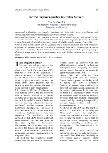
Data flow diagrams Data flow diagrams show the movement ofdata in the system.They use four symbols: a square box showsthe source or destination of data, a rectanglewith rounded corners shows the process (theaction to be performed on the data), an openended rectangle shows where data is stored,and arrows shows the flow of data.Figure 10.4 An example of a data flow diagramNetworks and Communication Department
Data Flow Diagramming RulesTABLE 7-2 Rules Governing Data Flow Diagramming
Data Flow Diagramming Rules (Cont.)TABLE 7-2 Rules Governing Data Flow Diagramming (cont.)
Data flow diagram example Figure 10.4 shows a simplified version of a bookingsystem in a small hotel that accepts reservation frompotential guests through Internet and confirms ordenies the reservation based on available vacancies.Networks and Communication Department
Procedure-oriented analysis (Cont.) Entity-relationship diagrams Another modeling tool used during the analysis phase is theentity-relationship diagram.The database designer creates an ER diagram to show the entitiesfor which information needs to be stored and the relationshipbetween those entities.State diagrams State diagrams provide another useful tool that is normally usedwhen the state of the entities in the system will change inresponse to events.As an example of a state diagram, we show the operation of aone-passenger elevator. When a floor button is pushed, theelevator moves in the requested direction. It does not respond toany other request until it reaches its destination.Networks and Communication Department
State diagrams (Cont.) State is represented by rounded rectangle in the state diagramFigure 10.5 Shows a state diagram for this old-style elevatorNetworks and Communication Department
Object-oriented analysis Object-oriented analysis is the analysis process used if theimplementation uses an object-oriented language. Thespecification document in this case may use several tools,but we discuss only a few of them here.Use case diagrams Ause-case diagram gives the user’s view of a system:it shows how users communicate with the system. A use-case diagram uses four components: system, usecases, actors and relationships. A system, shown by arectangle, performs a function.Networks and Communication Department
Use case diagrams The action (Function) in the system are shown by use cases,which are denoted by rounded rectangles.An actor is someone or something that uses the system, whichrepresented by stick figuresFigure 10.6 shows the use case diagram forNetworksthe old-styleelevatorDepartmentand Communication
Class diagrams The next step in analysis is to create a class diagram for the system.For example, we can create a class diagram for our old-styleelevator. To do so, we need to think about the entities involved inthe system.Figure 10.7 An example of a class diagramNetworks and Communication Department
State chart After the class diagram is finalized, a state chartcan be prepared for each class in the class diagram.A state chart in object-oriented analysis plays thesame role as the state diagram in procedureoriented analysis. This means that for the classdiagram of Figure 10.7, we need to have a fourstate chart.Networks and Communication Department
DESIGN PHASEThe design phase defines how the system willaccomplish what was defined in the analysisphase. In the design phase, all components of thesystem are defined. Procedure-oriented design: Inprocedure-oriented design we have bothprocedures and data to design. We discuss a categoryof design methods that concentrate on procedures. Inprocedure-oriented design, the whole system isdivided into a set of procedures or modules.Networks and Communication Department
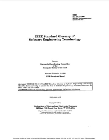
Structure charts A common tool for illustrating the relations betweenmodules in procedure-oriented design is a structurechart. For example, the elevator system whose statediagram is shown in Figure 10.5 can be designed as aset of modules shown in the structure chart in Figure10.8.Figure 10.8 A structure chartNetworks and Communication Department
Modularity Modularity means breaking a large project intosmaller parts that can be understood and handledeasily.In other words, modularity means dividing a largetask into small tasks that can communicate with eachother.The structure chart discussed in the previous sectionshows the modularity in the elevator system. Thereare two main concerns when a system is divided intomodules: coupling and cohesionNetworks and Communication Department
Modularity (Cont.) Coupling is a measure of how tightly two modulesare bound to each other.The more tightly coupled, the less independent theyare.Since the objective is to make modules asindependent as possible, we want them to beloosely coupled.Coupling between modules in a software systemmust be minimized.Networks and Communication Department
Modularity (Cont.) Another issue in modularity is cohesion. Cohesionis a measure of how closely the modules in asystem are related. We need to have maximumpossible cohesion between modules in a softwaresystem.Cohesion between modules in a software systemmust be maximized.Networks and Communication Department
Object-oriented design In object-oriented design the design phase continues byelaborating the details of classes.a class is made of a set of variables (attributes) and aset of methods. The object-oriented design phase listsdetails of these attributes and methods. Figure belowshows an example of the details of our four classesused in the design of the old-style elevator.Figure 10.9 An example of classes with attributes and methodsNetworks and Communication Department
IMPLEMENTATION PHASEIn the waterfall model, after the design phase iscompleted, the implementation phase can start. In this phase the programmers write the code forthe modules in procedure-oriented design, orwrite the program units to implement classes inobject-oriented design. There are several issues we need to mention ineach case. Networks and Communication Department
Choice of languageIn a procedure-oriented development, the projectteam needs to choose a language or a set oflanguages. Although some languages like C areconsidered to be both a procedural and an objectoriented language—normally an implementationuses a purely procedural language such as C. In the object-oriented case, both C and Java arecommon. Networks and Communication Department
Software quality The quality of software created at theimplementation phase is a very important issue.A software system of high quality is one thatsatisfies the user’s requirements, meets theoperating standards of the organization, and runsefficiently on the hardware for which it wasdeveloped.However, if we want to achieve a software systemof high quality, we must be able to define someattributes of quality.Networks and Communication Department
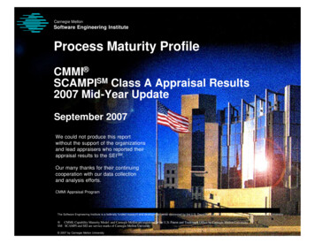
Software quality factors Software quality can be divided into three broadm e a s u r e s : o p e r a b i l i t y, m a i n t a i n a b i l i t y a n dtransferability. Each of these measures can be furtherbroken down as shown in Figure below.Networks and Communication DepartmentFigure 10.10 Quality factors
Software quality factors Operability refers to the basic operation of asystem.Several measures can be mentioned for operability:accuracy, efficiency, reliability, security, timeliness,and usability.Networks and Communication Department
Software quality factors (Cont.) Maintainability refers to the ease with which asystem can be kept up to date and runningcorrectly. Many systems require regular changes,not because they were poorly implemented, butbecause of changes i
set of methods. The object-oriented design phase lists details of these attributes and methods. Figure below shows an example of the details of our four classes used in the design of the old-style elevator. Figure 10.9 An example of classes with attributes and methods