Transcription
SIII RDATIO N S T A NIIIIIIIIIIIIUCIIIIRDIISTRevision* CT CONIIIIIIIIII7 thIIDUIIII I I I I IIIIIIIIIRD INDU I IAW S IIIIIIIIIIIIIIII IIIIES TR IIIIII* Revised to be in compliance with SMACNA HVACDuct Construction Standards, 2nd ed., 1995.Duct Construction StandardsForPositive & NegativeStatic PressuresAndSubmittal DataEngineering SpecificationsPROJECTSUBMITTED BYLOCATIONCONSULTANTS TO THE SHEET METAL INDUSTRYENGINEERDATE111 Riverview Drive Monessen, PA 15062 (724) 684-5500 1-800-466-9374 FAX (724) 684-8697 www.wardind.comCOPYRIGHT 1998WARD INDUSTRIES
ForewordTEST RESULTSThe following tests of rectangular duct sections and transverse joints were conducted in accordance withSection VII of the SMACNA HVAC Duct Construction Standards, 2nd ed., 1995.For twelve years Ward Industries has pioneered the use of the four-bolt system for transverse ductconnection. Ward Industries was one of the first to bring the four-bolt connector to the market andthrough engineering and innovation it has also been a leader in improvements.Over the years, Ward customers have successfully installed over 375 million feet of flange in thousands of installations. Examples of Ward products at work are shown below.David L. Lawrence Convention Center – Pittsburgh, PACertified copies of these tests are available upon request.WARD INDUSTRIES WILL PERFORM ANY ADDITIONAL TESTING THAT ANY ENGINEER,ARCHITECT, AUTHORITY, OWNER OR CONTRACTOR WOULD DEEM NECESSARY.OPERATINGPRESSUREDUCT FLECTIONDUCTDEFLECTION1”72/1260”18 ga.H.249.6501”48/1260”26 ga.H.050.7501”60/2160”26 ga.J.060.7501”84/1260”R24 ga.J.072.3841”96/1260”20 ga.J.290.7501”84/2160”T26 ga.J.060.3502”60/2160”T26 ga.J.050.0102”84/1248”18 ga.J.250.7402”72/1260”R24 ga.H.258.7252”72/1260”19 ga.J.2302”48/1260”24 ga.H.120.650.8202”84/3684/2160”R20 ga.J.168.6702” see note60”T26 ga.J.040.4683”48/1260”20 ga.H.165.7303”72/1260”R24 ga.60/1260”18 ga.140.131.7023”JJ3”60”R20 ga.J.22060”H.148J72/1224 ga.J.090.231.0404”60”T60”R16 ga.26 ga.500.7403”76/4460/1560/214”48/1260”R24 ga.H.164.4984”48/1260”20 ga.H.245.8304”60/1260”18 ga.J.160*4”76/4460”R20 ga.J.278.6004”60/2160”T26 ga.J.120.10060”R60”24 ga.18 ga.HH.210.525 .75060”18 ga.J3”Because of the Four – Bolt Connection, the 20’ wide sections of ductwork can be lifted into placewith a forklift. Using this method, more than 40 feet of the huge system can be installed per day.IRS Service Buildings – Memphis, Tennessee42 Miles of Ward H and J Flange InstalledTested at 9” Static PressureLess than 1% 1248”R20 60”18 ga.H.300.7806”60/1260”18 ga.J.279*10”42/1248”16 ga.H.200.73010”108/5860”R18 ga.J.250 .75010”120/4242/2448”R60”R16 ga.16 ga.JJ.100.090 .750.34010”Building Complexes cover over 30 acres under one roof.*.250R Midpoint ReinforcementT Conduit Type Tie Rods* These tests were done as comparative tests, and the actual duct deflection was not recorded. They did not exceed SMACNA Deflection Standards.Note: Two (2) Tie Rods — equally spaced (28” Centerline) were usedRectangular DuctDeflection Limits(As taken from the SMACNAHVAC Duct ConstructionStandards, 2nd ed., 1995.)Duct WallW 12” or lessW 13” to 18”W 19” to 24”W 25” to 84”W 85” to 120”Tolerance of 10%Joints & ReinforcementsW 48” or lessW 49” to 120”Tolerance of 200
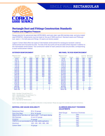
WARD INDUSTRIES SYSTEMS ARE . . . . . . . AN ENERGY SAVING DUCT REINFORCEMENT CONNECTIONTHE THREE WARD INDUSTRIES SYSTEMS . . .provide an innovative means of joining two sections of sheet metal ductwork andprovide a stronger, tighter leakproof duct connection which . . . Lower the cost of the sheet metal installation and provide a significant savings in operating costs.WARD INDUSTRIES COMPONENTSRecommended for 26 ga. through and including 14 ga. ductworkJ SYSTEMRollformed from 20 ga.galvanized steel.11 Ga. Galvanized CornerJ CORNER11 ga. galvanized steelRoll formed from20 ga. galvanized steelH SYSTEMRollformed from 22 ga.galvanized steel.11 Ga. Galvanized CornerLarge sealant pocket on all three flange systemsSEALANTFlame Spread - 5Smoke Density - 0Fuel Contribution - 0Life Expectancy - 20 year minimumE SYSTEMRollformed from 26 ga.galvanized steel.No Corners Neededpatent#5450879H CORNER11 ga. galvanized steelWARD INDUSTRIES METAL CLEAT Available in both 6” pieces and 10’ lengths Suitable for driving in tight installations Also available in PVCWARD INDUSTRIES GASKETAvailable in Butyl and Closed Cell NeopreneNEOPRENE GASKETFlame Spread - 10Fuel Contribution - 0Smoke Density - 0Thickness - 5/16”Unlimited Shelf LifeBUTYL GASKETFlame Spread - 20Fuel Contribution - 0Smoke Density - 0Thickness - 3/16”Life Expectancy - 20 yr. min.Flash Point - 300 FCompression set - none1
2
1/2” W.G.Staticpos or negDuctDimen.SHOP STANDARDSRECTANGULAR DUCT REINFORCEMENTMinimum Rigidity Class* - Minimum Gage DuctReinforcement Spacing8’6’5’4’3’2 1/2’2’26” 2”H-18H-20H-22 J26TH-24H-24H-24H-2473-84”J-16H-18H-22 18 J22T H-20J2297-108”J22T J-18 J22T J-18 J22T H-18 J-22 H-18 J-22 H-18109-120”J22TJ22TJ22TJ-18 J22T H-18 J-22 H-18J22J22When referring to Table 1-3 thru Table 1-10 in the SMACNA HVAC Duct ConstructionStandards, 2nd ed., 1995,Use the Ward “E” Angle on Rigidity Class “E” and below;Use the Ward “H” Angle on Rigidty Class “F”, “G” and “H”Use the Ward “J” Angle on Rigidity Classes above “H”The tables as shown herein are the SMACNA Tables with those interpretations already substituted.By conducting Joint Performance Testing as described in Section VII of the SMACNA HVACDuct Construction Standards, 2nd ed., 1995, it was found that in some tests, the Ward Angles(E,H and J) permitted a more liberal interpretation of the SMACNA Tables.These tests results are shown as follows:SMACNA TableVariationpermitted percertified test.It is understood that some awarding authorities might not permit the “variation” even though its acceptance is described inthe SMACNA HVAC Duct Construction Standards, 2nd ed., 1995, and therefore both options have been shown. The resultsof these certified tests which permit the variation are shown on the back page of this manual. Also, both options have beenshown, so as to provide this manual as a quick reference to SMACNA Standards.1 Other 4 bolt manufacturers have prepared duct construction standards, but Ward Industries is the only manufacturerthat is in full compliance with the SMACNA HVAC Duct Construction Standards 2nd ed. in so much as they have hadall of their flanges tested in accordance with Chapter 7, and also have certified tests from an outside independent testinglaboratory (Pittsburgh Testing Laboratories) for all the optional variations from the SMACNA HVAC Duct ConstructionStandards 2nd ed. as shown.3
SHOP STANDARDS1” W.G.Staticpos or negDuctDimen.RECTANGULAR DUCT REINFORCEMENTMinimum Rigidity Class* - Minimum Gage DuctReinforcement Spacing8’6’5’4’3’2 1/2’2’14” E-24E-24 H-26E-26E-26E-26E-2637-42”H-20E-22E-24 H-26E-26E-26E-26E-2643-48”H-18H-20H-22 H-26H-26E-26E-26E-2649-54”H-18H-20H-22 J26 H-24 J-26 E-24 J-26 E-24 J-26 E-24 J-2655-60”H-18H-20H-22 J26 H-24 J-26 H-24 J-26 E-24 J-26 E-24 J-2661-72”H-1824H-18 JJJJH-22 J26T H-24 J26T H-24 J-26 H-24 J-2626T73-84”J-16J-18 J24T J-20JJ22 H-22J-16 J-20 J-18 J-2085-96”J22 H-22 J-24 H-22 J-24J-20 J22 H-20 J-2297-108”J22T J-18 J22T J-18 J22T J-18109-120”J22TH-22J-22 J-18 J-22J22T J-18 J22T J-18 J-22 J-18 J-22* Each duct system shall be constructed for the specific duct pressure classifications shown on the contract drawings for the project. Where no specific duct pressure class designations are provided by thedesigner, the 1” water gage pressure class is the basis of compliance with these standards, regardless ofvelocity in the duct, except when the duct is variable volume: All variable volume duct upstream of VAVboxes has a 2” w.g. basis of compliance when the designer does not give a pressure class.*Because total pressure decreases in the direction of the flow, a duct construction pressure classificationequal to fan outlet pressure ( or to fan total static pressure rating) cannot economically be imposed on theentire duct system. Pressure in ducts near room air terminals is nearly always below 1/2” w.g.*Asterisks indicate wording that is taken directly and verbatim from the SMACNA HVAC Duct ConstructionStandards, 2nd ed., 1995.SMACNA TABLE 1-2 DUCT SEALING REQUIREMENTSSeal ClassClassSealing RequiredStatic PressureConstruction ClassAAll transverse joints, longitudinalseams and duct wall penetrations4” w.g. and upBAll transverse joints andlongitudinal seams3” w.g.CTransverse Joint2” w.g.In addition to the above, any variable air volume system duct of 1” and 1/2” w.g. construction class that isupstream of the VAV boxes shall meet Seal Class C.4
2” W.G.Staticpos or negDuctDimen.SHOP STANDARDSRECTANGULAR DUCT REINFORCEMENTMinimum Rigidity Class* - Minimum Gage DuctReinforcement Spacing8’6’5’4’3’2 1/2’2’12” H-20H-22 E-24E-24E-26E-26E-2637-42”H-16H-18H-20 E-24E-24E-24E-26E-26H-18H-20H-22 -16 J24T J-18 J26TH-22H-22 2T J-18 J22T J-20 J-24 J-22 J-24 J-22H-2485-96”J22T J-18 J22T J-18 J-20 J-20 J-22 J-22J-2297-108”JT22TJT22T K-18 JT22T J-18 J-22 J-18J-22109-120”JT22TJT22TJ-22JT22T K-18 J-22 J-18Tie Rod InstallationsTIE ROD OPTION CONSTRUCTION:Using the Ward RODLOCK (Conduit Type Tie Rod) Ward Industries, in their certified testing program(in accordance with Chapter 7 of the SMACNA HVAC Duct Construction Standards, 2nd ed., 1995)has used the Rodlock being attached to the duct wall alone as the reinforcement for the panel tie rod.Example: 22 T Center tie rod:Where the Rodlock is used as a flange reinforcement, “JT” or “HT”, the conduit type tie rod is installedas shown below:Negative PressureNOTE: Do not use internal duct wall supports (tie rods) on negative pressureduct systems without first consulting with Ward Industries Inc.5
3” W.G.Staticpos or negDuctDimen.SHOP STANDARDSRECTANGULAR DUCT REINFORCEMENTMinimum Rigidity Class* - Minimum Gage DuctReinforcement Spacing8’6’5’4’3’2 1/2’2’12” dnE-24E-26E-26E-26E-26E-26E-2613-18”E-22E-24E-24 H-26E-26E-26E-26E-2619-22”E-20E-22E-24 H-26 E-24 H-26E-26E-26E-2623, 24”E-18E-22E-24 H-26 E-24 H-26E-26E-26E-2625, 26”H-18E-22E-24E-24E-26E-26E-2627, 28”H-18H-20H-22 E-24E-24E-26E-26E-2629, 30”H-18H-20H-22 E-24E-24E-26E-26E-2631-36”H-16H-18H-20 E-24 H-22 E-24 H-24 E-24E-26E-2637-42”H-18H-20 E-24 H-22 E-24 H-24 E-24 H-24 E-2443-48”J-16J-18 J26T H-20 J26TH-22H-24H-2449-54”J-18 J26T J-18 J26TH-22H-24H-2455-60”J-16 J24T J-18 J24TH-20H-22H-24E-2661-72”J24T J-16 J24T J-20 J24T J-22 J-24J-2473-84”J20TJ20T J-18 J20T J-20 J-22J-2285-96”JT20TJT20T K-18JT20T J-18 J-20J-2097-108”JT20TJT20TJT20T L-18 JT20K-18 JT20109-120”JT20TJT20TJT20T L-18 JT20L-18 JT20This table shows some typical duct sizes and the weight that can be savedby changing gage per certified test:SMACNA TableDuct SizeSq. Ft. per5” Sect.Variation permitted per certified test.Lbs./Sq. Ft.Lbs./Sq. FtLbs./Sq. Ft.Lbs./Sq. Ft.Lbs./Sq. Ft.911.161.411.662.1626 ga.24 ga.22 ga.20 ga.18 017120126196/481201201531862192856
SHOP STANDARDS4” W.G.Staticpos or negDuctDimen.RECTANGULAR DUCT REINFORCEMENTMinimum Rigidity Class* - Minimum Gage DuctReinforcement Spacing8’6’5’4’3’2 1/2’2’10” 26E-26E-2623-26”H-18H-20H-22 E-24E-24E-26E-26E-2627-30”H-18H-18H-22 E-24 H-24 E-24E-26E-26E-2631-36”H-18H-20 H-22H-24H-26E-2637-42”J-16J-18 H-22 H-20 H-22H-22H-24H-2643-48”J-18 J26T J-18 J26TH-22H-24H-2449-54”J-16 J24T J-18 J24TJ-20H-22H-2455-60”J-16 J22T J-16 J22TJ-20J-22H-24H-2261-72”J20TJ20T J-18 J-20 J-20 J-24 J-22 H-2473-84”J20TJ20T K-16 J20T J-18 J-20 J-20 J-2285-96”JT20TJT20TJT20T K-18 JT2097-108”JT18TJT18TJT20T L-18 JT20 L-18109-120”JT18TJT18TJT18T L-18 JT18 L-18 JT18J-20JT20PRECAUTIONSIn any given duct system, accidental over pressure could occur and must be accounted for by design provisions, suchas fail safe features, replaceable release panels and static pressure switches that can shut down the entire system.Note: On all duct systems that are to be tested for leakage, it is recommended that the first100 feet of completed ductwork be tested before proceeding to complete the installation.SHIPPING L SHAPED DUCT WITH THE ANGLE INSTALLEDSTEP ONESTEP TWOSTEP THREESTEP FOURComplete the frame andbend over the hammeredge of the Pittsburgh Lockin the standard manner.Notch the “hammer edge”of the female PittsburghLock 1/4” on a 45 degreeangle as shownIn the shop, install theangle on the duct withoutthe corner piece.In the field insert a cornerpiece into the angle at themale end of the PittsburghLock7
6” W.G.Staticpos or negDuctDimen.SHOP STANDARDSRECTANGULAR DUCT REINFORCEMENTMinimum Rigidity Class* - Minimum Gage DuctReinforcement Spacing8’6’5’4’3’2 1/2’2’10” 2615,18”E-18E-20E-22E-24E-26E-26E-2
Duct Construction Standards, 2nd ed., 1995,it was found that in some tests, the Ward Angles (E,H and J) permitted a more liberal interpretation of the SMACNA Tables. These tests results are shown as follows: SMACNA Table Variation permitted per certified test. It is understood that some awarding authorities might not permit the “variation” even though its acceptance is described in the .