Transcription
Installation Manual20002158, Rev DNOctober 2020Micro Motion ELITE Coriolis Flow andDensity Sensors
Safety messagesSafety messages are provided throughout this manual to protect personnel and equipment. Read each safety message carefullybefore proceeding to the next step.Safety and approval informationThis Micro Motion product complies with all applicable European directives when properly installed in accordance with theinstructions in this manual. Refer to the EU declaration of conformity for directives that apply to this product. The EU declarationof conformity, with all applicable European directives, and the complete ATEX Installation Drawings and Instructions are availableon the internet at www.emerson.com or through your local Micro Motion support center.Information affixed to equipment that complies with the Pressure Equipment Directive, can be found on the internet atwww.emerson.com.For hazardous installations in Europe, refer to standard EN 60079-14 if national standards do not apply.Other informationFull product specifications can be found in the product data sheet. Troubleshooting information can be found in the configurationmanual. Product data sheets and manuals are available from the Micro Motion web site at www.emerson.com.Return policyFollow Micro Motion procedures when returning equipment. These procedures ensure legal compliance with governmenttransportation agencies and help provide a safe working environment for Micro Motion employees. Micro Motion will not acceptyour returned equipment if you fail to follow Micro Motion procedures.Return procedures and forms are available on our web support site at www.emerson.com, or by phoning the Micro MotionCustomer Service department.Emerson Flow customer serviceEmail: Worldwide: flow.support@emerson.com Asia-Pacific: APflow.support@emerson.comTelephone:2North and South AmericaEurope and Middle EastAsia PacificUnited States800-522-6277U.K. and Ireland0870 240 1978Australia800 158 727Canada 1 303-527-5200The Netherlands 31 (0) 70 4136666New Zealand099 128 804Mexico 52 55 5809 5010France 33 (0) 800 917901India800 440 1468Argentina 54 11 4809 2700Germany0800 182 5347Pakistan888 550 2682Brazil 55 15 3413 8000Italy 39 8008 77334China 86 21 2892 9000Chile 56 2 2928 4800Central & Eastern 41 (0) 41 7686111Japan 81 3 5769 6803Peru 51 15190130Russia/CIS 7 495 995 9559South Korea 82 2 3438 4600Egypt0800 000 0015Singapore 65 6 777 8211Oman800 70101Thailand001 800 441 6426Qatar431 0044Malaysia800 814 008Kuwait663 299 01South Africa800 991 390Saudi Arabia800 844 9564UAE800 0444 0684
Installation Manual20002158ContentsOctober 2020ContentsChapter 1Before you begin. 51.1 About this document. 51.2 Hazard messages. 51.3 Related documentation. 6Chapter 2Planning. 72.1 Installation checklist. 72.2 Best practices. 82.3 Temperature limits. 92.4 Recommendations for hygienic and self-draining applications.12Chapter 3Mounting.153.1 Recommendations for lifting heavy meters. 153.2 Mount the sensor.163.3 Rotate junction box or 800 core processor (optional).183.4 Mount electronics of high-temperature sensors. 193.5 Mount a CMF010 sensor to a wall or pole. 223.6 Mount a CMFS007, CMFS010 or CMFS015 sensor in a bracket. 233.7 Mount a CMFS025, CMFS040 or CMFS050 sensor in a wall mount bracket. 243.8 Secure wafer-style process connections.253.9 Attach extended electronics. 27Chapter 4Transmitter power and I/O wiring. 294.1 Options for wiring. 294.2 Connect 4-wire cable. 304.3 Connect the 9-wire cable . 34Chapter 5Grounding.35Chapter 6Supplementary information. 376.1 Purge the sensor case .376.2 Pressure relief. 39Installation Manual3
ContentsOctober 20204Installation Manual20002158Micro Motion ELITE
Installation Manual200021581Before you begin1.1About this documentBefore you beginOctober 2020This document provides information on planning, mounting, wiring, and grounding theELITE sensor.The information in this document assumes that users understand basic transmitter andsensor installation, configuration, and maintenance concepts and procedures.1.2Hazard messagesThis document uses the following criteria for hazard messages based on ANSI standardsZ535.6-2011 (R2017).DANGERSerious injury or death will occur if a hazardous situation is not avoided.WARNINGSerious injury or death could occur if a hazardous situation is not avoided.CAUTIONMinor or moderate injury will or could occur if a hazardous situation is not avoided.NOTICEData loss, property damage, hardware damage, or software damage can occur if asituation is not avoided. There is no credible risk of physical injury.Physical accessNOTICEUnauthorized personnel can potentially cause significant damage and/or misconfigurationof end users' equipment. Protect against all intentional or unintentional unauthorized use.Physical security is an important part of any security program and fundamental toprotecting your system. Restrict physical access to protect users' assets. This is true for allsystems used within the facility.Installation Manual5
Before you beginOctober 20201.3Installation Manual20002158Related documentationYou can find all product documentation on the product documentation DVD shipped withthe product or at www.emerson.com.See any of the following documents for more information: The hazardous area approvals documentation shipped with the sensor or available atwww.emerson.com/flowmeasurement. Micro Motion ELITE Coriolis Flow and Density Meters Product Data Sheet Micro Motion 9-Wire Flow Meter Cable Preparation and Installation Guide The transmitter installation and configuration and use guides6Micro Motion ELITE
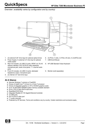
Installation Manual20002158PlanningOctober 20202Planning2.1Installation checklist If you plan to mount the transmitter in a hazardous area:WARNINGMake sure that the hazardous area specified on the approval tag is suitable for theenvironment in which the meter will be installed. Verify that the local ambient and process temperatures are within the limits of themeter. If your sensor has an integral transmitter, no wiring is required between the sensor andtransmitter. Follow the wiring instructions in the transmitter installation manual forsignal and power wiring. If your transmitter has remote-mounted electronics, follow the instructions in thismanual for wiring between the sensor and the transmitter, and then follow theinstructions in the transmitter installation manual for power and signal wiring.Table 2-1: Maximum lengths for Micro Motion cableCable typeTo transmitterMaximum lengthMicro Motion 9-wire9739 MVD transmitter1,000 ft (305 m)All other MVD transmitters60 ft (18 m)All 4-wire MVD transmitters— 1,000 ft (305 m) withoutEx-approvalMicro Motion 4-wire— 500 ft (152 m) with IICrated sensors— 1,000 ft (305 m) with IIBrated sensorsTable 2-2: Maximum lengths for user-supplied 4-wire cableWire functionWire sizeMaximum lengthPower (VDC)22 AWG (0.326 mm²)300 ft (91 m)20 AWG (0.518 mm²)500 ft (152 m)18 AWG (0.823 mm²)1,000 ft (305 m)Signal (RS-485) Installation Manual22 AWG (0.326 mm²) or larger 1,000 ft (305 m)For optimal performance, install the sensor in the preferred orientation. The sensor willwork in any orientation as long as the flow tubes remain full of process fluid.7
PlanningOctober 2020Installation Manual20002158Table 2-3: Preferred sensor orientationProcessPrimary preferredorientationSecondary preferredorientationAlternate suitableorientationLiquids & slurriesGasesLiquid with bubblesWet gasTwo-phase 2.2Install the meter so that the flow direction arrow on the sensor case matches the actualforward flow of the process. (Flow direction is also software-selectable.)Best practicesThe following information can help you get the most from your sensor. There are no pipe run requirements for Micro Motion sensors. Straight runs of pipeupstream or downstream are unnecessary. If the sensor is installed in a vertical pipeline, liquids and slurries should flow upwardthrough the sensor. Gases should flow downward. Keep the sensor tubes full of process fluid. For halting flow through the sensor with a single valve, install the valve downstreamfrom the sensor.8Micro Motion ELITE
Installation Manual20002158PlanningOctober 2020 The sensor does not require external supports. The flanges will support the sensor inany orientation. (Some sensor models installed in very small, flexible pipeline haveoptional installation instructions that allow for external supports.)2.3Temperature limitsSensors can be used in the process and ambient temperature ranges shown in thetemperature limit graphs. For the purposes of selecting electronics options, temperaturelimit graphs should be used only as a general guide. If your process conditions are close tothe gray area, consult with your Micro Motion representative.Note In all cases, the electronics cannot be operated where the ambient temperature isbelow -40 F (-40.0 C) or above 140 F (60.0 C). If a sensor is to be used where theambient temperature is outside of the range permissible for the electronics, theelectronics must be remotely located where the ambient temperature is within thepermissible range, as indicated by the shaded areas of the temperature limit graphs. Temperature limits may be further restricted by hazardous area approvals. Refer to thehazardous area approvals documentation shipped with the sensor or available atwww.emerson.com/flowmeasurement. The extended-mount electronics option allows the sensor case to be insulated withoutcovering the transmitter, core processor, or junction box, but does not affecttemperature ratings. When insulating the sensor case at elevated processtemperatures above 140 F (60.0 C), ensure electronics are not enclosed in insulationas this may lead to electronics failure. For the CMFS007 sensor, the difference between the process fluid temperature and theaverage temperature of the case must be less than 210 F (99 C)Installation Manual9
PlanningOctober 2020Installation Manual20002158Ambient and process temperature limits for CMFS007, CMFS025–CMFS150B140 (60)140 (60)113(45)TambA–40 (–40)B–148 (–100)–58 (–50)400 (204)TprocTamb Ambient temperature F ( C)Tproc Process temperature F ( C)A All available electronic optionsB Remote mount electronics onlyAmbient and process temperature limits for CMF***M/L/H/P (excludes special ordercryogenic modifications) and CMFS010-015140(60)140 (60)TambACB113(45)–40 (–40)B–148 (–100)–400(–240)-148(-100)Tproc400(204)Tamb Ambient temperature F ( C)Tproc Process temperature F ( C)A All available electronic optionsB Remote mount electronics onlyC Recommend special order cryogenic sensor options when operating at a processtemperature below -148 F (-100 C)10Micro Motion ELITE
Installation Manual20002158PlanningOctober 2020Ambient and process temperature limits for special order cryogenic ELITE meters140 (60)TambA–40 (–40)B–148 (–100)–400(–240)Tproc176(80)Tamb Ambient temperature F ( C)Tproc Process temperature F ( C)A All available electronic optionsB Remote mount electronics onlyAmbient and process temperature limits for high temperature ELITE meters140 (60)TambA–40 (–40)B–148 (–100)–58(–50)Tproc662(350)Tamb Ambient temperature F ( C)Tproc Process temperature F ( C)A All available electronic optionsB Remote mount electronics onlyInstallation Manual11
PlanningOctober 2020Installation Manual20002158Ambient and process temperature limits for super duplex ELITE meters140 (60)B140 (60)113(45)TambA–40 (–40)B–148 (–100)–40 (–40)Tproc400 (204)Tamb Ambient temperature F ( C)Tproc Process temperature F ( C)A All available electronic optionsB Remote mount electronics onlyNoteFor super duplex models operating above 351 F (177.2 C), consult the factory beforepurchase.2.4Recommendations for hygienic and selfdraining applicationsCMFS sensors are certified EHEDG TYPE EL CLASS I for hygienic applications when installedvertically with the process fitting and gasket combinations listed in the Position Paper ofthe EHEDG Test Methods Subgroup (available at https://www.ehedg.org). Other processconnections/gasket combinations may be used provided they have been evaluated andsuccessfully tested for in-place cleanability according to the latest edition of EHEDGDocument 2. Refer to the ELITE Product Data Sheet for further information about fittingoptions.For optimal cleanability and drainability: If possible, install the sensor in a vertical pipeline with the process fluid flowing upwardthrough the sensor. If the sensor must be installed in a horizontal pipeline, drainage is accomplished by airpurge evacuation of the pipeline circuit. For clean-in-place (CIP) applications, Micro Motion recommends using the generallyaccepted flow velocity of at least 1.5 m/s for cleaning the sensor. The gap between the electronics housing and sensor body should be inspectedperiodically. Manually clean this gap when necessary.12Micro Motion ELITE
Installation Manual20002158PlanningOctober 2020Figure 2-1: Installation for self-draining applicationsABCA. Process pipelineB. Direction of normal process flowC. Direction of drainageInstallation Manual13
PlanningOctober 202014Installation Manual20002158Micro Motion ELITE
Installation Manual20002158MountingOctober 20203Mounting3.1Recommendations for lifting heavy metersHeavy meters (those over 50 lb (23 kg), and even lighter meters that must be installed inelevated or difficult-to-reach places, usually require additional consideration whentransporting or lifting them into their installation location. Safe handling during transportation and installation is the responsibility of the installerCAUTIONKnow and follow all safety practices and regulations for your facility and for anylifting/rigging equipment being used in order to prevent injury. A professional rigging crew with proper equipment should be used Typical equipment for handling heavy meters includes the following:— Fixed hoist boom trucks or cranes— Continuous web belt slings— Eye to eye web belt slings— Two leg wire rope slings Lift a meter by its case. Do not lift a meter by its electronics (junction box, transmitter, or any electrical fittings)or by its purge fittings It may be useful to identify the meter center of gravity Protect the sealing surfaces on the process fittings with factory-installed flangeprotectors or comparable field-installed protectionInstallation Manual15
MountingOctober 2020Installation Manual20002158Figure 3-1: Acceptable lifting pointsFigure 3-2: Center of gravity for large metersAA. Typical center of gravityNoteComplete and detailed dimensional drawings, including the location of the center ofgravity, can be found through the product drawings link in our online store atwww.micromotion.com/onlinestore .3.2Mount the sensorNOTICE Lifting the sensor by the electronics or purge connections can damage the device.16Micro Motion ELITE
Installation Manual20002158MountingOctober 2020 To reduce the risk of collecting liquid in the electronics housing, do not orienttransmitters or sensor junction boxes with their conduit openings pointing upward.ProcedureMount the sensor.Notes Do not use the sensor to support the piping. The sensor does not require external supports. The flanges will support the sensor inany orientation.Some sensor models installed in small, flexible pipelines have optionalinstallation instructions that allow for external supports.Installation Manual17
MountingOctober 20203.3Installation Manual20002158Rotate junction box or 800 core processor(optional)An integrally mounted junction box or 800 core processor can be rotated to one of eightpossible positions in 45 degree increments.Figure 3-3: Parts for rotating the junction box or 800 core processor on the sensorABDECA.B.C.D.E.HousingClamping ringClamping ring screwFeedthroughAlignment notchesNoteThe 800 core processor is shown in this figure. The junction box has a somewhat differentappearance.Procedure1. Loosen the clamping ring screw and remove the clamping ring.2. Gently separate the housing from the feedthrough, but only until there is sufficientclearance from the alignment notches to rotate the housing.3. Rotate the housing to the desired position and in line with the alignment notches.4. Seat the housing onto the feedthrough.5. Replace the clamping ring and tighten the clamping ring screw.18Micro Motion ELITE
Installation Manual200021583.4MountingOctober 2020Mount electronics of high-temperature sensorsThe electronics of high-temperature sensors are attached to the end of a 32 in (813 mm)pre-installed flexible conduit. The electronics must be separately mounted on a wall orinstrument pole.Figure 3-4: Components of a high-temperature sensorABCDA.B.C.D.SensorElectronicsMounting bracketFlexible conduit with minimum bend radius 6 in (152 mm)With some large meter sizes, the meter may ship with the electronics attached to thesensor case. The meter cannot be operated in this configuration. Detach the electronicsbracket from the sensor case and then proceed to mount the electronics to a wall orinstrument pole as described below.ImportantDo not operate the meter while the electronics are attached to the sensor case.Installation Manual19
MountingOctober 2020Installation Manual20002158Figure 3-5: Removing electronics from the sensor caseAA. Detach electronics from sensor case and
forward flow of the process. (Flow direction is also software-selectable.) 2.2 Best practices. The following information can help you get the most from your sensor. There are no pipe run requirements for Micro Motion sensors. Stra