Transcription
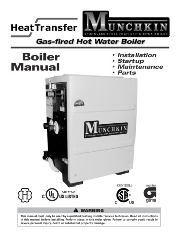
NINGThis manual must only be used by a qualified heating installer/service technician. Read all instructionsin this manual before installing. Perform steps in the order given. Failure to comply could result insevere personal injury, death or substantial property damage.
GAS-FIRED BOILERBoiler ManualCONTENTSPart 1 – Product and Safety Information . . . . . . . . . . . . . . . . . . . . . . . . . . . . . . . . . . . . . 3, 4Part 2 – How The Boiler Operates . . . . . . . . . . . . . . . . . . . . . . . . . . . . . . . . . . . . . . . . . . . 5-9Part 3 – Prepare Boiler Location . . . . . . . . . . . . . . . . . . . . . . . . . . . . . . . . . . . . . . . . . . . . 6-12A.B.C.D.E.F.G.H.Boiler Location Should Be LevelInstallations Must Comply With:Before Locating BoilerClearances for Service AccessResidential Garage InstallationExhaust Vent and Intake Air VentPrevent Combustion Air ContaminationWhen Removing a Boiler from an Existing Common Vent SystemPart 4 – Prepare Boiler . . . . . . . . . . . . . . . . . . . . . . . . . . . . . . . . . . . . . . . . . . . . . . . . . . . . . 12A. Remove Boiler from BoxPart 5 – Boiler Piping . . . . . . . . . . . . . . . . . . . . . . . . . . . . . . . . . . . . . . . . . . . . . . . . . . . . 12-24– Boiler Piping Details . . . . . . . . . . . . . . . . . . . . . . . . . . . . . . . . . . . . . . . . . . . . . . . . 18-24A.B.C.D.E.F.G.H.I.J.K.L.M.Relief ValveGeneral Piping InformationSeparate Low Water CutoffBackflow PreventerSystem Water Piping MethodsCirculatorsHydronic Piping with Circulators, Zone Valves and Multiple BoilersCirculator SizingFill and Purge Heating SystemZoning with Zone ValvesZoning with CirculatorsMultiple BoilersBoiler Piping DetailsPart 6 – Boiler Piping with Vision 1 System . . . . . . . . . . . . . . . . . . . . . . . . . . . . . . . . . . . . 25– Boiler Piping Details With Vision I System . . . . . . . . . . . . . . . . . . . . . . . . . . . . . . 26-35A.B.C.D.Vision 1 System PipingZoning with Zone Valves Using Vision IZoning with Circulators Using Vision IBoiler Piping Details with the Vision I SystemPart 7 – Venting Combustion Air And Condensate Removal. . . . . . . . . . . . . . . . . . . . 36-44– Venting Details. . . . . . . . . . . . . . . . . . . . . . . . . . . . . . . . . . . . . . . . . . . . . . . . . . . . . 42-44A.B.C.D.E.G.H.I.J.K.1Installing Exhaust Vent and Intake Air VentGeneralApproved Materials for Exhaust Vent and Intake Air VentExhaust Vent and Intake Air Vent Pipe Location.Exhaust Vent and Intake Air Vent SizingExhaust Vent and Intake Air Pipe Installation.Heater Removal from a Common Vent SystemCondensate Removal SystemDiagrams for Side Wall VentingDiagrams for Vertical Venting
GAS-FIRED BOILERBoiler ManualCONTENTS (CONT’D)Part 8 – Gas Piping. . . . . . . . . . . . . . . . . . . . . . . . . . . . . . . . . . . . . . . . . . . . . . . . . . . . . . 45-47A.B.C.D.Gas ConnectionGas PipingGas TableDungs Gas ValvePart 9 – Field Wiring. . . . . . . . . . . . . . . . . . . . . . . . . . . . . . . . . . . . . . . . . . . . . . . . . . . . . 47-49A.B.C.D.Installation Must Comply WithField WiringLine Voltage WiringThermostatPart 10 – Field Wiring – Vision 1 . . . . . . . . . . . . . . . . . . . . . . . . . . . . . . . . . . . . . . . . . . . . . 50Part 11 – Start Up Preparation . . . . . . . . . . . . . . . . . . . . . . . . . . . . . . . . . . . . . . . . . . . . 51-53A.B.C.D.E.F.G.H.Check/Control Water ChemistryFreeze Protection (when used)Fill and Test Water SystemPurge Air from Water SystemCheck for Gas LeaksCheck Thermostat Circuit(s)Condensate RemovalFinal Checks Before Starting BoilerPart 12 – Start-Up Procedure . . . . . . . . . . . . . . . . . . . . . . . . . . . . . . . . . . . . . . . . . . . . . 53-55A.B.C.D.Operating InstructionsAdjusting the Set PointStatus MenuTest ModePart 13 – Start-Up Procedures With The Vision 1 Option . . . . . . . . . . . . . . . . . . . . . . 55-58A. Programming the Vision I OptionB. Vision I Program AccessC. Vision I Program NavigationPart 14 – Trouble Shooting . . . . . . . . . . . . . . . . . . . . . . . . . . . . . . . . . . . . . . . . . . . . . . . 59-61A. Munchkin Error CodeB. Boiler ErrorC. Boiler FaultPart 15 – Maintenance. . . . . . . . . . . . . . . . . . . . . . . . . . . . . . . . . . . . . . . . . . . . . . . . . . . 61-66A. Maintenance ProceduresB. Combustion Chamber Coil Cleaning InstructionsPart 16 – Boiler Inspection and Maintenance Start-Up Charts . . . . . . . . . . . . . . . . . . 67-692
Boiler ManualGAS-FIRED BOILERPART 1: PRODUCT AND SAFETY INFORMATIONSPECIAL ATTENTION BOXESThe following defined terms are used throughout this manual to bring attention to the presence ofhazards of various risk levels or to important information concerning the product.DEFINITIONSDANGERCAUTIONDANGER indicates an imminently hazardoussituation which, if not avoided, will result indeath or serious injury.CAUTION Indicates a potentially hazardoussituation which, if not avoided, may result inminor or moderate injury.WARNINGCAUTIONWARNING indicates a potentially hazardoussituation which, if not avoided, could result indeath or serious injury.CAUTION used without the safety alert symbolindicates a potentially hazardous situation which,if not avoided, may result in property damage.WARNINGIf the information in this manual is not followed exactly, a fire or explosion may result causing property damage, personal injury or loss of life.Do not store or use gasoline or other flammable vapors andliquids in the vicinity of this or any other appliance.WHAT TO DO IF YOU SMELL GAS Do not try to light any appliance. Do not touch any electrical switch: do not use any phone inyour building. Immediately call your gas supplier from a neighbor's phone.Follow the gas supplier's instructions. If you cannot reach your gas supplier, call the fire department.Installation and service must be performed by a qualifiedinstaller, service agency or the gas supplier.NOTICEHeat Transfer Products, Inc., reserves the right to make product changes or updates without noticeand will not be held liable for typographical errors in literature.3
Boiler ManualGAS-FIRED BOILERPART 1: PRODUCT AND SAFETY INFORMATION (CONT’D)WARNINGInstaller — Read all instructions in this manual,and Munchkin Venting section, before installing.Perform steps in the order given.User — This manual is for use only by aqualified heating installer/service technician.Refer to User’s Information Manual for yourreference.supply at a location external to the appliance. BOILER WATER If you have an old system with cast ironradiators, thoroughly flush the system (withoutboiler connected) to remove sediment. Thehigh-efficiency heat exchanger can be damagedby build-up or corrosion due to sediment. Do not use petroleum-based cleaning or sealingcompounds in boiler system. Gaskets and sealsin the system may be damaged. This can resultin substantial property damage. Do not use “homemade cures” or “boiler patentmedicines.” Substantial property damage,damage to boiler, and/or serious personal injurymay result. Continual fresh make-up water will reduce boilerlife. Mineral buildup in heat exchanger reducesheat transfer, overheats the stainless steel heatexchanger, and causes failure. Addition ofoxygen carried in by make-up water can causeinternal corrosion in system components. Leaksin boiler or piping must be repaired at once toprevent make-up water.User — Have this boiler serviced/inspected bya qualified service technician annually.Failure to comply with the above could result insevere personal injury, death or substantialproperty damage.WARNINGFailure to adhere to the guidelines on this pagecan result in severe personal injury, death orsubstantial property damage.WARNINGWHAT TO DO IF YOU SMELL GAS Do not try to light any appliance. Do not touch any electric switch; do not useany phone in your building. Immediately call your gas supplier from aneighbor's phone. Follow the gas suppliers'instructions. If you cannot reach your gas supplier, call thefire department.Before InstallingWHEN SERVICING BOILER To avoid electric shock, disconnect electricalsupply before performing maintenance. To avoid severe burns, allow boiler to coolbefore performing maintenance.BOILER OPERATION Do not block flow of combustion orventilation air to boiler. Should overheating occur or gas supply fail toshut off, do not turn off or disconnect electricalsupply to circulator. Instead, shut off the gasDo not use this boiler if any part has beenunder water. Immediately call a qualifiedservice technician to inspect the boiler and toreplace any part of the control system andany gas control that has been under water.FREEZE PROTECTION FLUIDSCAUTIONNEVER use automotive or standard glycolantifreeze, even ethylene glycol made forhydronic systems. Use only inhibited propyleneglycol solutions, which are specificallyformulated for hydronic systems. Ethyleneglycol is toxic and can attack gaskets and sealsused in hydronic systems.CAUTIONConsider piping and installation whendetermining boiler location. Any claims fordamage or shortage in shipment must be filedimmediately against the transportationcompany by the consignee.4
Boiler ManualGAS-FIRED BOILERPART 2: HOW BOILER OPERATESMunchkin Condensing Technology is an intelligent system that delivers highly efficient hydronic heating, while maximizing efficiency by measuring the Data Parameters of your heating system.1. Stainless Steel Heat ExchangerThe highly efficient durable MunchkinStainless Steel Heat Exchanger is designed totake the colder return water from the systemand extract the last bit of energy before it isexhausted. The heat exchanger design isseparated by an internal baffle which divertsthe exhaust gas through the primary heatexchanger into the secondary heat exchangerwhere the colder return water extracts the lastresidual heat.2. Modulating Combustion SystemModulation during the central heatingoperation is based on the supply temperature.The set point used for the control dependsupon the programmed central heating curve.The slope of the heating curve can be changedby the installer of the Munchkin in the sensethat both turning points of the curve can bemoved. The control monitors the system toregulate the output of the burner duringoperation to match the system demand. Thisincrease in efficiency allows for substantial fuelsavings.3. Gas ValveThe gas valve senses suction from the blower,allowing gas to flow only if the gas valve ispowered and combustion air is flowing.4. Supply water temperature sensorThis sensor monitors boiler output watertemperature (system supply). The controlmodule adjusts the boiler firing rate so theoutlet temperature is correct.5. Return water temperature sensorThis sensor monitors the return watertemperature (system return). The controlmodule reduces or increases boiler input,depending on how close the return watertemperature is to the outlet watertemperature.6. Temperature and pressure gaugeAllows the user to monitor the systems5temperature and pressure.7. ControlThe integrated control system monitors thereturn and supply water and regulates the fanspeed to regulate the unit’s BTU output. Thisallows the unit to only deliver the amount ofheated energy required and nothing more!8. BurnerConstructed of high grade stainless steelconstruction, the burner uses pre-mixed airand gas and provides a wide range of firingrates.9. Electrical field connections with terminalstripsThe electrical cover plate allows access theline voltage terminal strip and the low voltageterminal strip. Attach line voltage conduits tothe three holes at the right of the line voltageterminal strip for power, CH pump and DHWpump. Route low voltage wires through theopening to the left of the low voltage terminalstrip. (See Field Wiring Instructions Part 9.)10. Condensate drain connectionThis is a condensing high efficiency appliance,therefore this unit has a condensate removalsystem. Condensate is nothing more thanwater vapor, derived from the combustionproducts, similar to an automobile when it isinitially started. It is very important that thecondensate line is sloped away from the boilerand down to a suitable inside drain, if thecondensate outlet on the Munchkin is lowerthan the drain, you must use a condensateremoval pump (kit p/n 554200 available fromHeat Transfer Products, Inc.) A condensatefilter, if required by local authorities can bemade up of lime crystals, marble or phosphatechips and will neutralize the condensate. Thiscan be done in the field by the installer or youmay purchase one from Heat TransferProducts, Inc. (P/N N1100). It is also veryimportant that the condensate line is notexposed to freezing temperatures or any othertype of blockage. Plastic tubing must be theonly material used for the condensate line.Steel, brass, copper or others will be subjectto corrosion or deterioration. A second ventmay be necessary to prevent condensate linevacuum lock if a long horizontal run is used.
Boiler ManualGAS-FIRED BOILERPART 2: HOW BOILER OPERATES (CONT’D)Also, an increase in pipe size may benecessary to drain properly. Support of thecondensation line may be necessary to avoidblockage of the condensate flow.11. Spark ignitionThe burner flame is ignited by applying a highvoltage to the system spark electrode. Thiscauses a spark from electrode to ground.12. The Vision 1 SystemThe Vision I System will allow the installingcontractor to take the highly efficientmodulating Munchkin and make it even moreefficient by controlling the temperaturedelivered to the central heating circuits basedon the outside temperature. The Vision Isystem is also a two temperature system, onetemperature for central heating and the othertemperature to the Super Stor Ultra Indirectwater heater. This allows the user to increasethe temperature supplied to the Super StorUltra indirect water heater to get a fastrecovery by prioritizing the flow at a highertemperature than may be needed for thecentral heating circuits (this will require twoseparate circulators). You must follow thepiping, wiring and programming instructionslocated in the Vision One section of thismanual. The Vision 1 kit consists of thefollowing, which is included with yourequipment Outdoor sensor – 7250P-319 Indirect tank sensor – 7250P-325PART 3: PREPARE BOILER LOCATIONA. BOILER LOCATION SHOULD BE LEVELCAUTIONWhen preparing the boiler location, make sure the area where you are placing the boiler is level. In orderfor the condensate to flow to the location of the condensate hose, the boiler must be slightly pitchedback to assure proper flow direction. The Munchkin Boiler comes equipped with leveling feet. Shouldyou find the floor beneath the boiler is uneven, with a wrench, adjust the leveling feet so the boiler ispitched back at 1/8” per footINCORRECTCORRECT6
Boiler ManualGAS-FIRED BOILERPERFORMANCE RATINGSCONNECTION SIZESModelInput ModulationDOE HeatingAFUET50MT80M80M140M199M399M18,000 to 50,00019,000 to 80,00027,000 to 80,00046,000 to 140,00066,000 to 199,000100,000 to 399,00016,000 to 46,00017,000 to 74,00025,000 to 74,00043,000 to 129,00061,000 to 183,00093,000 to 279,00092%92%92%92%92%92%DIMENSIONST50M/T80MFigure 2-17ShippingWeight*IBR58 lbs. 40,00058 lbs. 64,00075 lbs. 64,000101 lbs. 112,000111 lbs. 159,000252 lbs.N/ASupply/GasVentReturn ConnectionDia.ConnectionSize1 1/4" NPT3/4"2"1 1/4" NPT3/4"2"1 1/4" NPT3/4"3"1 1/4" NPT3/4"3"1 1/4" NPT3/4"3"2" NPT1-1/4"4"FAN 40015501675
GAS-FIRED BOILERBoiler ManualDIMENSIONS80MFigure 2-2140M/199MFigure 2-38
Boiler ManualGAS-FIRED BOILERDIMENSIONS399MFigure 2-4PART 3: PREPARE BOILER LOCATION (CONTINUED)B. INSTALLATIONS MUST COMPLY WITH: Local, state, provincial, and national codes,laws, regulations and ordinances. National Fuel Gas Code, ANSI Z223.1 – latestedition. Standard for Controls and Safety Devices forAutomatically Fired Boilers, ANSI/ASMECSD-1, when required. National Electrical Code. For Canada only: B149.1 or B149.2Installation Code, CSA C22.1 CanadianElectrical Code Part 1 and any local codes.NOTICEThe Munchkin Boiler gas manifold and controlsmet safe lighting and other performance criteriawhen boiler underwent tests specified in ANSIZ21.13 — latest edition.9C. BEFORE LOCATING THE BOILER1. Check for nearby connection to: System water piping Venting connections Gas supply piping Electrical power2. Check area around boiler. Remove anycombustible materials, gasoline and otherflammable liquids.WARNINGFailure to keep boiler area clear and free ofcombustible materials, gasoline and otherflammable liquids and vapors can result insevere personal injury, death or substantialproperty damage.3. The Munchkin gas control system componentsare protected from dripping or spraying water
Boiler ManualGAS-FIRED BOILERPART 3: PREPARE BOILER LOCATION (CONTINUED)or rain during operation or service.WARNING4. If the Munchkin Boiler is to replace anexisting boiler, check for and correct anyexisting system problems such as: System leaks. Incorrectly-sized expansion tank. Lack of freeze protection in boiler watercausing system and boiler to freeze and leak. Excessive glycol which will affect theboiler system operation.The space must be provided with combustion/ventilation air openings correctly sized forall other appliances located in the same space asthe Munchkin boiler. The boiler cover must be securely fastened to the boiler to prevent boilerfrom drawing air from inside the boiler room.This is particularly important if the boiler is located in the same room as other appliances.Failure to comply with the above warnings couldresult in severe personal injury, death or substantial property damage.D. CLEARANCES FOR SERVICE ACCESS1. See Figure 3-1 for recommended serviceclearances. If you do not provide minimumclearances shown, it might not be possible toservice the boiler without removing it fromthe space.80M/140M/199M/399ME. RESIDENTIAL GARAGE INSTALLATIONPrecautionsTake the following special precautions wheninstalling the boiler in a residential garage. If theboiler is located in a residential garage, per ANSIZ223.1, paragraph 5.1.9: Mount the boiler with a minimum of 18inches above the floor of the garage to thebottom of the boiler to ensure the burner andignition devices will be no less than 18 inchesabove the floor. Locate or protect the boiler so it cannot bedamaged by a moving vehicle.F. EXHAUST VENT AND INTAKE AIR VENTT50M/T80MThe Munchkin Boiler requires a special vent system, designed for pressurized venting.Munchkin Boilers are rated ANSI Z21.13Category IV (pressurized vent, likely to condense in the vent).You must also install air intake piping from outside to the boiler flue adaptor. The resultantinstallation is categorized as direct vent (sealedcombustion). Note: To prevent combustionair contamination see Table 3-2 in thissection when considering exhaust ventand intake air vent termination.Intake and exhaust must terminate near eachother and may be vented vertically through theroof or out a side wall. The intake and exhuastventing methods are detailed in the VentingSection. Do not attempt to install the MunchkinBoiler using any other means. Be sure to locatethe boiler such that the air intake and exhaustFigure 3-1: Clearances required10
Boiler ManualGAS-FIRED BOILERPART 3: PREPARE BOILER LOCATION (CONTINUED)vent piping can be routed through the buildingand properly terminated. The air intake andexhaust vent piping lengths, routing and termination method must all comply with the methodsand limits given in the Venting section.G. PREVENT COMBUSTION AIR CONTAMINATIONInstall intake air piping for the Munchkin Boileras described in the Venting section. Do not terminate exhaust in locations that can allow contamination of intake air.WARNINGYou must pipe outside air to the boiler airintake. Ensure that the intake air will notcontain any of th
Feb 20, 2007 · Munchkin Condensing Technologyis an intelli-gent system that delivers highly efficient hydron-ic heating, while maximizing efficiency by meas-uring the Data Parameters of your heating sys-tem. 1. Stainless Steel Heat Exchanger The highly efficient durable Munchkin Stainless Steel Heat Exchanger is designed to take the colder return water from .