Transcription
UserManualThe Hercules PatientRepositioner SystemTM#8106 Rev. 1.0SIZEWISE04.07.2015User Manual
Table of ContentsDefinition of Symbols . 3Manual Definitions . 3Warnings and Cautions . 3Device Information . 4Description of the Device . 4Purpose of the Device . 4Indications for Use . 4Specifications . 5Unpacking and Set-Up Instructions . 6Unpacking Instructions for the 39” SW Lowboy /Evolution . 7Set-Up Instructions for the 39” SW Lowboy /Evolution . 8Unpacking/Installation Instructions: SW Bari-Rehab Platform2 . 20Operating Instructions . 29Control Unit Operation . 29Hercules Patient Repositioner . 30Hercules Support Surface/Mattress. 32Positioning Sheet . 33Patient Care Functions . 34Placing the Patient on the Support Surface/Mattress . 34Re-Positioning the Patient. 35Prone Position . 35Changing The Positioning Sheet With A Patient In Bed . 35Safety Tips . 40Seven Zones of Bed Rail Entrapment . 40Storage and Disposal. 41Important Safety Instructions . 42Unpacking and Set-Up Instructions . 42Electrical Safety Tips . 42Support Surface Cleaning Safety Instructions . 431
Warnings . 43Cautions . 43Cleaning Instructions . 45Cleaning the Top Cover and Sheet Clips: . 45Cleaning the Hercules Patient Repositioner . 46Positioning Sheet Laundry Instructions . 47Maintenance . 48Troubleshooting . 49Service Instructions . 50Hercules Patient Repositioner Replacement . 50Full Support Surface Replacement . 50Power Cord Replacement . 51Sheet Attachment Strap Replacement . 52Frequently Ordered Parts . 53Obtaining Parts and Service . 53Warranty Information . 541 Year Limited Warranty: Drive Unit . 5490 Day Limited Warranty: Top Cover . 543 Year Limited Warranty: Support Surface/Mattress . 54User Assistance Information . 552
Definition of SymbolsManual DefinitionsThroughout this manual different type fonts and icons are used to aid user readability andunderstanding of the content. Below are some examples.Standard TextBold Face TextNOTE:Used for regular information.Emphasizes a word or phrase.SETS APART SPECIAL INFORMATION OR IMPORTANTINSTRUCTION CLARIFICATION.Warnings and CautionsWarnings/Cautions: This symbol is intended to alert the user to the presence ofimportant operating, maintenance or servicing instructions. Disregarding awarning could result in patient and/or user injury as well as damage to equipment.Electrical Shock Hazard Warning: This symbol is intended to alert the user tothe presence of electrical shock hazards. It is important to follow all instructionsand special procedures to avoid electrical shock to the operator, care providerand/or patient.3
Device InformationDescription of the DeviceThe Hercules Patient Repositioner System consists of: Drive Unit-Conveniently located, includes user interface and simple to use.Support Surface/Mattress-Utilizes advanced open cell technology providingcomfortable support for patients up to 750 lbs. (340 kg)Specialized Sheet-Soft and comfortable fabric with an increased length that allows 8-10positioning’s per sheet.Purpose of the DeviceThe Hercules Patient Repositioner allows a single caregiver to reposition a patient up in bed withthe simple push of a button. Now, in 10 seconds, the Hercules Patient Repositioner can helpimprove caregiver safety, increase caregiver efficiency, eliminate caregiver distractions, andprotect your patient’s dignity.Indications for UseThe Hercules Patient Repositioner is intended to assist caregivers with up-in-bed patientrepositioning. It is designed for use in acute care and post acute care settings in which atraditional hospital or healthcare bed is used. It is designed to be a key component in any safepatient handling program.4
Specifications DimensionsMode of Use . For Indoor Use OnlyPositioning Sheet Dimensions . (LxW) 16’ (487.7cm) x 46”(116.8 cm)Positioning Sheet Material . . . .100% PolyesterHercules Patient Repositioner Dimensions . (LxWxH) 38.5”( 97.8cm) x 11”( 27.9cm) x3.75”(9.5cm)Hercules Patient Repositioner Weight . . . 48 Lbs. ( 21.7 kg) ElectricalPower Requirements 120VAC 60Hz 4.0A MaximumElectric Shock Protection. .Class 1Degree of Shock Protection . .Type BFuses . T 6.3A 250V .5mm x 20 mm Time DelayMode of Operation .Continuous with Intermittent Loading. .25 min ON/29.75 min OFFPower Cord . detachable, hospital grade.13’ (396cm) Support Surface Standard Dimensions 39” . . .(LxWxH) 80”(203.2cm) x 38”(96.5cm) x 7”(17.8cm)Standard Mattress Weight 39” . . .36 lbs(16.8 kg)Standard Weight Capacity 39” . .Up to 750 lbs (272-340 kg) Environmental ConditionsTemperature for storage and transport . .-29oC to 60oC (-20.2 F) to (140 F)Relative Humidity for storage and transport . 10%-95% Relative HumidityAtmospheric Pressure for transport, storage and use . . 70 kPa-106 kPaTemperature for use . 10oC t0 40oC (50 F) to (104 F)Relative Humidity for use . . . 20%-85% Relative HumidityProduct must be stored and transported in packaging free of moisture and dust.5
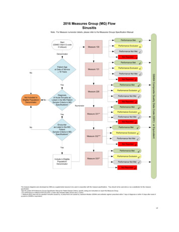
Unpacking and Set-Up InstructionsUnpacking/Parts Breakdown Positioning Sheet Hercules Patient Repositioner Support Surface/MattressHercules Patient RepositionerSupport Surface/MattressPositioning Sheet6
Unpacking Instructions for the 39” SW Lowboy /Evolution Remove the products from the packing material and examine for shipping damage. If damage isdetected in shipping, contact the freight company and file a damage complaint immediately.Included Items:7
Set-Up Instructions for the 39” SW Lowboy /Evolution NOTE: Read “Important Safety Instructions” prior to assembly/set-up.(See Table Of Contents)Tools Required:Follow these steps for installation on bedframes:1. Remove headboard from bed and raise head of bed slight to access front edge of headsection.2. Remove support surface retainer by removing the two clips on the underneath of the supportsurface then lifting up.8
3. Unplug the bed and any bed attached accessory outlet.4. Place the Hercules Patient Repositioner box on bed. Open and fold back top of box. Gentlyflip unit onto open side. Pull box up to reveal contents. Gently lay the back down andremove packaging.9
5. Position the Hercules Patient Repositioner on top of the head section with the mounting holesfacing the end of the bed.6. Hook one of the bed brackets under the deck section of the bed. Lift the bed bracket upwhile pushing the bracket outward towards the transverse bar. Fasten the bracket of theHercules Patient Repositioner with two screws. These screws utilize the 4th and 5th threadedholes from the outside end.10
7. Repeat step 6 for the other bed bracket.8. With the head of the bed 20 degrees, place the power cord in the slot between the headsection and seat section of bed between the pivots of the sections. Feed the power cordthrough this opening.11
9. Plug in bed. Raise head section of bed to its highest limit. Unplug bed. Route the powercord on top of middle frame tube with bed cables. Attach power cord to middle frame tubewith wire tie close to the lift reaction plate. Do Not Tighten the Wire Tie At This Time.12
10. This step is to ensure the power cord has proper slack. Plug in the bed. Lower the headsection down to 10 degrees. Unplug the bed. Tighten wire tie placed in previous step.13
11. Plug in the bed. Raise head section of the bed to its highest limit. Unplug the bed. Attachpower cord to the middle frame tube with a wire tie in the approximate center length of themiddle tube, close to the existing bed wire tie. Fully tighten wire tie. Attach the power cordto middle frame tube with a wire tie at the end of the middle frame tube, close to the existingbed wire tie.14
12. Attach the power cord to middle frame tube with wire tie “C” at the end of the middle frametube, close to the existing bed wire tie. Fully tighten wire tie.15
13. Use wire ties “D” and “E” to connect the power cord to bed power cord on the outboard sideof the bed strain relief. These wire ties should be placed approximately 2 inches from thestrain relief and 4 inches apart. Trim all placed wire ties.16
14. To install the support surface, lower the head of the bed. Unpackage the support surface andplace on the bed. Lift up on the head end of the support surface to access the mattressattachment strap. Slide loop of mattress attachment straps over grasp attached to theHercules Patient Repositioner. Repeat for the other side.15. Plug in the bed. Articulate the head of the bed examining for possible pinching of the powercord. If pinching does exist, re-perform all appropriate steps to ensure properinstallation. Ensure no patient entrapment risks exist between installed drive unit,sleep surface and the bed frame. Plug in the Hercules Patient Repositioner. If bed hasscale, re-zero the scale. Please read the user manual prior to using product.16. Unfold the positioning sheet at the foot end of the support surface and place on the sheetshelf located between the support surface and toe board.17
17. Pull the leading edge of the positioning sheet (the end containing buttonholes and “AdvanceSheet” graphics) towards the head end of the bed.18. Connect the positioning sheet to the sheet attachment strap by inserting the black caps intothe buttonholes on each side at the head end of the sheet.18
19. Secure the sheet by pulling the beaded hem into the sheet clips along both sides of thesupport surface starting at the foot end of bed and clip the sheet up toward the head section.Do not attach sheet to last clip on either side of support surface closest to head section.20. Press the “Unlock” button and the “Advance” button at the same time to advance the sheet.Continue advancing the sheet until the “Advance Sheet” graphics have completely passedbeyond the head end edge of the support surface.21. Secure sheet clips closest to head section on both sides of support surface.19
Unpacking/Installation Instructions: SW Bari-Rehab Platform2 Remove the products from the packing material and examine for shipping damage. If damage isdetected in shipping, contact the freight company and file a damage complaint immediately.20
Set-Up Instructions: SW Bari-Rehab Platform2 Tools Required:1. Plug in bed. Remove headboard from bed and raise head of bed slightly to accessfront edge of the head section.21
2. Unplug the bed and any bed-attached accessory outlet.3. Remove the Hercules Patient Repositioner from its packaging. Place the HerculesPatient Repositioner on the top edge of the head deck with the mounting holes facingthe end of bed.4. Ensure that the drive unit is centered by measuring equal distances between bothsides of the bed frame.22
5. Position one of the brackets so that the lip is located behind the head section crosstube.6. Slide the bracket up so that the lip is located on the backside of the head sectioncross tube and the slots in the bracket line up with the third and fourth mountingholes (counting from the edge of the bed).23
7. Attach the bracket to the Hercules Patient Repositioner using two of the foursupplied screws. Do not fully tighten at this time.8. Repeat steps four through six for the other bracket. Tighten all 4 screws.24
9. Drop the power cord between the head section and seat section of the bed.10. Plug in the bed. Raise the head section of the bed to its highest limit. Unplug thebed.25
10. Cut existing wire tie that is located in the approximate middle of the wiring channel.11. Using the hole that the removed wire tie utilized, attach the power cord into thewiring channel along with the existing bed cables with one of the 11” wire ties.Ensure the power cord has enough slack to not contact the head lift frame.12. Secure the power cable again to the wiring channel with the other supplied 11” wiretie. Place the wire tie on the head-end side of the existing cable clamp.26
13. Following the bed cables, route the power cord under the cross brace. Secure thepower cord to the bed power cord with the two 5.5” inch wire ties provided. Space thewire ties approximately two inches apart. These cable ties should be on the “wall” sideof the P-clip.14. Remove the mattress restraint at the foot end of the bed.27
15. Plug in the bed and lower the head of the bed.Un-package the support surface and place on the bed. Lift up on the head end of thesupport surface to access the mattress attachment straps. Slide the loop of one of themattress attachment straps over the grasp attached to the Hercules Patient Repositioner.Repeat for the other side.16. Articulate the head of the bed and examine for possible pinching of the power cord.If pinching does exist, re-perform all appropriate steps to ensure proper installation. Cutall wire ties to length.17. For placement/installation of the Hercules Positioning Sheet, see the SW 39”Lowboy/Evolution set-up instructions step/number 16-20 and follow the procedure. (SeeTable of Contents)Ensure no patient entrapment risks exist between the patient and the installed HerculesPatient Repositioner System.Installation for this bed is complete.28
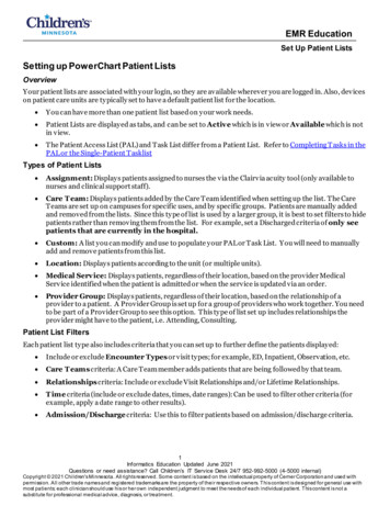
Operating InstructionsThe Hercules Patient Repositioner provides users the ability to reposition patients utilizing thebelow drive unit interface instructions.Control Unit Operation1. Power LED: A green LED that is illuminated when the Hercules Patient Repositioner isconnected to a power source.2. Head Up LED: An amber LED that is illuminated when the head of the bed is raised past30 degrees; the system will not advance the positioning sheet when this LED isilluminated.3. Door Open LED: An amber LED that is illuminated when the drive door is open; thesystem will not advance the positioning sheet when this LED is illuminated.4. Unlock Button: This button, represented by an unlatched padlock, must be pressed atthe same time as the “Advance” button to operate the system and advance the positioningsheet.5. Advance Button: This button, represented by an arrow, must be pressed at the sametime as the “Unlock” button to operate the system and advance the positioning sheet.6. Sheet Release Button With LED: When the user presses this button, an amber LEDwill illuminate allowing the roller to spin freely for removal of the positioning sheet. Toengage the roller and turn off the illuminated LED, press the “Advance” button and the“Unlock” button at the same time.29
Hercules Patient RepositionerThe Hercules Patient Repositioner drive unit is the power behind the Hercules PatientRepositioner System and is located at the head end of the bed just below the hinged head sectionof the support surface.1. User InterfaceControls are located on both sides of the Hercules Patient Repositioner, allowing for theoperation of the system and providing status LEDs.2. Mattress Attachment HooksThe two hooks located on the back wall of the Hercules Patient Repositioner are used to securethe support surface.3. Drive DoorThe hinged drive door allows access to the roller compartment for cleaning and servicingpurposes.4. Sheet Attachment StrapThe strap is used to connect the positioning sheet to the roller. The strap contains black caps thatare inserted into buttonholes on the head section of the positioning sheet.5. RollerThe roller connects to the sheet attachment strap and rotates to wind the sheet duringrepositioning.6. Sheet SlotNarrow access point on the drive unit providing an entryway for the sheet.30
Hercules Patient Repositioner Cont.43531
Support Surface/MattressSupport Surface1. Made with a tri-laminated high density foam core, and multi-zoned pressureredistribution top layer this mattress is designed for patient comfort and aids in theprevention of pressure ulcers.Hinged Head Section2. The upper head section of the support surface is hinged, allowing it to be easily lifted bythe user to access the Hercules Patient Repositioner.Mattress Attachment Straps3. The straps, located on the bottom of the support surface, are used to secure it to theHercules Patient Repositioner via the mattress attachment hooks.Sheet Clips4. The sheet clips, located along the side of the support surface, secure the positioning sheetand allow it to advance during repositioning.Sheet Shelf5. The shelf, located at the foot end of the support surface, supports the unused portion ofthe positioning sheet.32
Positioning SheetThe Positioning Sheet is 46” wide by 16’ long and allows for approximately 8-10 positioning’sper use.Sheet Loading Indicator1.The Load Indicator instructional markings (“Advance Sheet” graphics), located at the headend of the positioning sheet, indicate the distance and direction the sheet is to be advancedand how much sheet needs to be advanced into the drive unit prior to pulling patient weight.Buttonholes2.The two buttonholes, located in the head end of the positioning sheet, are used to connectthe positioning sheet to the sheet attachment strap.Beaded Hem3.The beaded blue hem, located along both lateral sides of the positioning sheet, enables thesheet to be secured into the sheet clips.Sheet Change Indicator4.Red triangles along the hem of the positioning sheet signal the amount of sheet remainingto be advanced. When the markers have reached the head end edge of the support surface, thesheet has reached its last pull and should be changed.33
Patient Care FunctionsPlacing the Patient on the Support Surface/MattressNOTE: Read Important “Safety Instructions” and “Safety Tips” before attempting anyPatient Care Function.Place the patient on the support surface from a bed or stretcher with a transfer device. In order toensure proper immersion and envelopment of the patient, the user should:1. CPR: The standards for life support recommended by the American Heart Association forperforming CardioPulmonary Resuscitation (CPR) recommend a hard level surface forperforming CPR, moving the person to the floor if possible. For performing CPR on theHercules Patient Repositioner, place a CPR board lower the head of the bed, position thepatient on their back and follow the standard CPR procedures of the facility.34
Re-Positioning the Patient1. Lower the head end of the bed to 30 or less and check that the amber Head Up and DoorOpen LEDs are not illuminated.2. Press the “Unlock” button and the “Advance” button at the same time to advance the sheet.Release when the patient has reached the desired position.NOTE: DO NOT leave a patient unattended on the support surface with the safety siderails in the down position. When leaving a patient, secure the safety side rails in the upposition. Make sure the safety side rails are high enough to properly protect the patient,while continuing to be mindful of the FDA guidelines on bed rail entrapment. (See Tableof Contents For Bed Rail Entrapment)Prone PositionDo not leave a patient positioned prone on the support surface. The decision to position a patientprone should be at the discretion of the facilities medical staff.Changing The Positioning Sheet With A Patient In BedNote: To change the positioning sheet with the patient in bed, please follow your standardfacility protocol for changing sheets while the patient remains in bed, along with theseadditional steps.1. Press the “Sheet Release” button located on the user interface to disengage the roller andrelease the positioning sheet from the drive unit. The amber “Sheet Release” LED willilluminate.35
2. Pull the positioning sheet out of the Hercules Patient Repositioner and disconnect it fromthe sheet attachment strap.3. Grasping each sheet clip, pull down to release the positioning sheet’s beaded hem on bothsides of the support surface.4. Unfold the new positioning sheet with the “Advance Sheet” graphics past the head endedge of the support surface. Ensure the “Advance Sheet” graphics are positionedcompletely beyond the head end edge of the support surface prior to placing thespecialized sheet under the patient. (This will allow enough sheet to properly load prior topulling patient weight in step 1)36
5. Unfold the positioning sheet along the side of the patient and place the remaining sheet atthe foot end of the sleep surface.6. Secure the positioning sheet to the side of the support surface you are working on bypulling the beaded hem into the sheet clips along that side of the support surface.7. Follow hospital protocol for rolling the patient and walk around to the other side of thebed.8. Remove the soiled positioning sheet.9. Secure the positioning sheet to the side of the support surface you are working on bypulling the beaded hem into the sheet clips along that side of the support surface.10. Connect the positioning sheet to the sheet attachment strap by inserting the black capsinto the buttonholes on both sides of the head end of the sheet.37
11. Press the “Unlock” button and the “Advance” button at the same time to advance thepositioning sheet until the patient is in the desired position.12. Place the remaining portion of the positioning sheet on the sheet shelf at the foot end ofthe support surface.13. Grasping the sheet clip, pull down to release the sheet’s beaded hem on both sides of thesupport surface.38
14. Press the “Sheet Release” button located on the user interface to disengage the roller andrelease the specialized sheet. The amber LED will illuminate.15. Pull the positioning sheet out of the Hercules Patient Repositioner and disconnect it fromthe sheet attachment strap.NOTE: Follow hospital protocols for sheet cleaning and laundry services.39
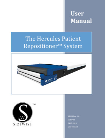
Safety TipsSeven Zones of Bed Rail EntrapmentIf the patient would have any clinical conditions that could result in risk of falling or improperlylying in bed, the bed should be left at its lowest setting and in flat position when not attended.Sizewise recommends the use of bed rails if they are available. There are seven zones of bed railentrapment.WARNING: Bed rail entrapment is a serious health risk that can result in seriousinjury or even death. Sizewise recommends the care provider be mindful of themost up to date FDA guidelines relevant to bed rail entrapment, as serious injurycan result. These guidelines can be found on the FDA website. When using anAir Therapy system the care provider is responsible for ensuring the mattressproperly fits the bed frame. It is also the care provider’s ultimate decision whetheror not to use bed rails with the patient.Zone 1: Within the RailZone 2: Under the Rail, Between the Rail Supports orNext to a Single Rail SupportZone 3: Between the Rail and the MattressZone 4: Under the Rail, at the Ends of the RailZone 5: Between Split Bed RailsZone 6: Between the End of the Rail and the SideEdge of the Head or FootboardZone 7: Between the Head or Footboard and theMattress EndZone OneZone TwoZone FourZone SixZone ThreeZone FiveZone Seven40
Storage and DisposalAlways store the support surface flat on a clean, level surface. Avoid storage of other equipmenton top of the support surface. DO NOT expose the Hercules Patient Repositioner System tohumidity greater than 95%.End-of-life Sizewise products must be disposed of properly according to local laws andregulations. Please contact Sizewise or your local authorities for disposal and recycling options.41
Important Safety InstructionsUnpacking and Set-Up Instructions Keep out of direct sunlight.(110V unit ONLY) Ensure the power cord is plugged into a properly grounded AC 110Voutlet.Electrical Safety Tips Medical equipment should not be used, stacked or located on or around equipment thatmay create electromagnetic interferences.Using other manufacturers’ cables and accessories may affect EMC performance.Unauthorized use of these items will void warranty and could result in patient and/or userinjury as well as damage to equipment or other property.DO NOT use the device if the power cord is cut, frayed or loosely connected.The potential for electrical shock exists with electrical equipment. Failure to follow theseinstructions and facility protocol could result in serious injury, death or equipmentdamage.Unplug the Hercules Patient Repositioner from the AC outlet before beginning anycleaning or service procedures. Failure to properly follow these instructions and facilityprotocol could result in serious injury, death or equipment damage.See specifications for main power requirements. Failure to do so may cause equipmentdamage.To avoid electrical shock, DO NOT open the Hercules Patient Repositioner. Referservicing to qualified personnel only.To protect against electric shock, grounding reliability can only be achieved when theequipment is connected to an equivalent receptacle marked “hospital only” or “hospitalgrade”. Failure to follow these instructions could result in serious injury, death orequipment damage.Medical electrical equipment needs special precautions regarding EMC performance andneeds to be installed and put into service accor
2. Unplug the bed and any bed-attached accessory outlet. 3. Remove the Hercules Patient Repositioner from its packaging. Place the Hercules Patient Repositioner on the top edge of the head deck with the mounting holes facing the end of bed. 4. Ensure that the drive unit is centered by measuring equal distances between both sides of the bed frame.