Transcription
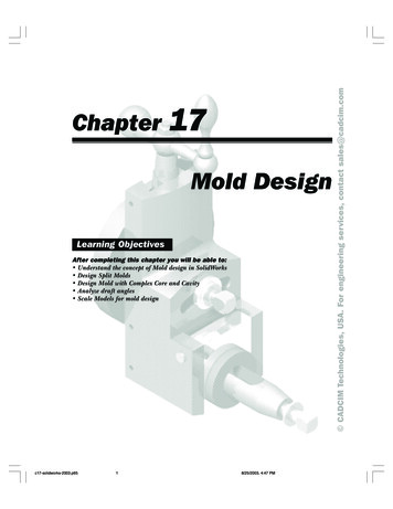
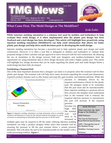
June 2020The Madison GroupJune 2020TMG NewsWhat Came First, The Mold Design or The Moldflow?Erik FoltzWhile injection molding simulation is a common tool used by molders and toolmakers to helpevaluate their mold design, it is often implemented after the plastic part design has beenfinalized and a tool design has been developed. This article will highlight how proactively usinginjection molding simulation (Moldflow ) can help yield information that allows for betterplastic part design and help drive mold decisions prior to developing the mold design.Injection molding simulation has become a powerful tool to help optimize plastic part design and moldconstruction. However, it is often a tool that is delegated to molders and toolmakers to validate theirproposed design to their customer and get approval to move forward with the tool construction. By delayingthe use of simulation in the design process, both part designers and molders/toolmakers limit theopportunity for using simulation data to drive design decisions and yield a higher quality part. This articlewill highlight key design decisions that can be made regarding the plastic part and mold designs before amold design has been fully developed.Establishing a Nominal WallOne of the most important decisions that a designer can make is to properly select the nominal wall for theirplastic part design. The nominal wall will help drive many decisions regarding the overall part dimensions,required auxiliary features such as ribs, bosses and snap fits, gate location, and material selection. While thisdecision is ultimately driven by therequired performance criteria for the plasticpart, the designer needs to be rememberthat the part must also be manufacturable.Since injection molding is a pressure-drivenflow process, the designer must understandthat as the nominal wall is reduced, therequired injection pressure to manufacturethe part will increase. If the requiredpressurebecomes tooInside This Issue:high, thenWhat Came First, The Moldthe nominal Design or The Moldflow?1Figure 1: Injection molding simulation can help determine what is a feasible wallwillnominal wall thickness of a part for the desired material and design of a prodFREE Webinars5need to beuct based on maintaining an attainable injection pressure to fill the mold.increased or The Case for PerformanceBased Material Specifications 6multiple gates may be required to fill the mold. Utilizing injection moldingsimulation can help a product designer better select that nominal wall by NEW—Through the Lens ofThe Madison Group9ensuring the pressure to fill the part remains below a certain pressurethreshold. This will allow the part to be manufacturable for the molder with a Moldflow Training Courses 10Webinars11wider processing window, Figure 1.Page 1madisongroup.com 2020 The Madison Group All Rights Reserved.
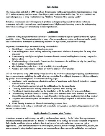
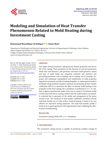
June 2020The Madison GroupTMG NewsWhat Came First, The Mold Design or The Moldflow? (cont.)Erik FoltzOnce the nominal wall thickness of the part has been established, the designer should avoid any unnecessarywall thickness variation in the part to avoid different cooling rates and potential part warpage duringmanufacturing. Additionally, the designer should drive their decisions regarding rib thickness and bossplacement based off the nominal wall selected.Evaluating Design Risk of Auxiliary FeaturesOnce the nominal wall thickness and overall appearance of the part have been established, the designer oftenturns their focus to adding in assembly features such as bosses, ribs, and snap fits. A quick review of bestplastic part design reveals that the base features are often dictated by a nominal wall section of the part.However, the integration of these design features introduce inherent wall thickness variability into the partthat could increase the risk of manufacturing issues such as sink orFigure 2: Mouse showing three mounting bosses. short shots, and design issues like dimensional stability. Figure 2shows a mouse that has three bosses used for assembly. By quicklyrunning a series of injection molding simulations the designer wasable to determine how the wall thickness of the bosses influencedthe predicted sink marks, or surface depression, which woulddevelop on the show surface, Figure 3. From this information thedesigner was able to determine how the inherent assembly andoperational stresses would change and ensure they remainedfeasible for the product design.Determining Feasible Gate LocationsOnce a product design has gone through some initial Design forManufacturing (DFM) analyses, the next design decision for themolder or toolmaker is often how to and where to place the gate to manufacture the part. The gate locationand type will dictate the mold construction, parting line decisions, and the need for secondary operations.Additionally, once again the design of thegate is often influenced by the wall thicknessof the part where the gate is located.As a general rule, the following guidelinescan be used to help select an appropriate gatelocation:1) Place the gate to force the material toflow from thick to thin areas of the part.Since injection molding is a pressure-drivenprocess the plastic will take the path of leastresistance. That means that as the materialstarts filling the mold, the molten resin willpreferentially flow in the thicker areas of thepart since the flow resistance is lower. Figure 3: Sink mark plot from Moldflow highlighting the predicted sinkmark depth with the original design vs. the optimized mouse and boss dePlacing the gate at the thickest wall section of sign.the part will help reduce any flow hesitationin the thinner areas, which will minimize any material cooling and decrease the pressure to fill the mold. Byplacing the gate at the thickest wall section of the part, the gate can be made large enough to maintainpressure on the cavity until the molten plastic has solidified. This will help mitigate any void formation orsink.Page 2madisongroup.com 2020 The Madison Group All Rights Reserved.
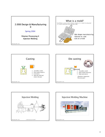
June 2020The Madison GroupTMG NewsWhat Came First, The Mold Design or the Moldflow? (cont.)Erik FoltzAs a general rule, the following guidelines can be used to help select an appropriate gate location: (cont.)2) Select a gate that will generate unidirectional filling pattern. The gate is the location in the mold wherethe material will start to fill in the mold cavity. By selecting a gate location that avoids any changes in flowdirection, the polymer molecules and any high aspect ratio fillers, such as glass or carbon fiber, will orientmore uniformly. By orienting themolecules and fillers more uniformly,that material will shrink moreconsistently and develop less stress in thepart that should lead to less partwarpage, Figure 4.3) Place weld lines in non-criticallocations. Weld lines are areas of a Figure 4: Images showing the predicted part deformation from two different gatemolded part where the molten material locations. Gate B helps produce a unidirectional filling pattern that helps reduceflow front split and then rejoin again. At the warpage in the part.the interface where the flow fronts rejoin,there is often limited molecular entanglement or fiber reinforcement in these areas, which can make themweaker, more brittle regions that have a higher probability of failure. Weld lines are a result of the flowprogression in the mold which is often driven by the gate location. Injection molding simulation can helpidentify the location of these weld lines, and can be compared to a stress distribution plot from a structuralFEA to see if the weld lines coincide with high stress or strain areas in the part, Figure 5. By proactivelyselecting a gate location that avoids placing these weaker areas in critical locations, the part performanceshould be improved.Selecting a MaterialDuring the design evaluation a great amount of time and effort are placed on selecting the correct resin for anapplication to help ensure robust part performance and obtaining the desired part aesthetics. However,material selection cannot be decoupled frommanufacturing, and often there are severalpotential material options that can be selectedfrom after the selection process is complete. Byutilizing injection molding simulation duringthe material selection process or at least earlyin the design phase, the optimal material forboth manufacturing and while in service canbe selected. By ensuring the material selectedis capable of meeting tolerances and partaesthetics prior to having first shots alsoFigure 5: Images showing the predicted weld line locations in a part coin- permits a wider possible selection ofciding with high stress areas, which could adversely affect the part perforalternative resins where shrinkage can bemance.adjusted in the 3D CAD. By waiting to havefirst shots, the manufacturer and designer aremore restricted to select a resin based on shrinkage value, that is less well suited for service in the field. Byintegrating injection molding simulation into the material evaluation the correct material can be selected forthe application and will avoid having to shoe-horn a material into an application that may result in asuboptimal part.Page 3madisongroup.com 2020 The Madison Group All Rights Reserved.
June 2020The Madison GroupTMG NewsWhat Came First, The Mold Design or the Moldflow?Erik FoltzBringing it All TogetherThe optimization of a plastic part design requires a holistic approach that dictates designers consider the partdesign, material selection, and manufacturing process collectively. Often in order to find a viable optionwithin each selection area there need to be trade-offs in other areas. By integrating injection moldingsimulation early on in the design phase any potential risk that could be detrimental to the part performancecan be identified prior to any mold construction, and actually help accelerate the mold design process byminimizing any rework.Need help driving your decision making to optimize your plastic part design?Contact our experts at Info@madisongroup.comAdditional case studies can also be found age 4madisongroup.com 2020 The Madison Group All Rights Reserved.
June 2020The Madison GroupTMG NewsAnnouncementsFREE—Virtual Personalized Training OpportunityAt The Madison Group, we firmly believe that knowledge is the key to success in any industry.Developing a fundamental understanding of plastics including material selection, design,processing and performance are essential to creating a robust product.The Madison Group would like to help you and your company build the understanding needed toachieve this through the following course offerings: Essentials of Plastic Failure Optimizing Part Design for Plastics Effective Interpretation of Plastic Molding Simulation How Processing is Affecting Your Part Performance Navigating Plastic Material Selection Creep Failure of PlasticsThese 1-hour sessions are designed to be interactive and promote dynamic team-based learning, andwill work best with 5 to 20 participants.If you are interested in scheduling a training session, please click here for more information on theindividual courses or to register your team. Please note that a limited number of sessions will beoffered on a first come, first serve basis!Information regarding upcoming educational opportunities can also be found at:https://www.madisongroup.com/events.htmlPage 5madisongroup.com 2020 The Madison Group All Rights Reserved.
June 2020The Madison GroupTMG NewsThe Case for Performance-Based Material SpecificationsMelissa KurtzImagine, after nearly two years of hard work, extensive testing, and various design iterations your newproduct has hit the market. There is nothing quite as exhilarating as creating a new product that will helpmake people’s lives better. Unfortunately, your joy is short-lived as the negative consumer feedback andproduct returns begin to build and your company’s reputable brand begins to tarnish.Your company engaged the failure analysis experts at The Madison Group and it led to some importantdiscoveries for you and your team. The component leading to the field failures experienced melting duringnormal operation. How could this be? After all, you performed lifetesting on the product constructed from production parts! TheMadison Group determined that the root cause of the issue was thatthe material used in the component from the field failures had verydifferent thermal behavior than the material initially used in thecomponent during the product testing phase.The material that had been selected for this component was a blendof nylon 6 and nylon 6/6 resins. It was called out on the drawingusing its specific tradename and grade. To their benefit, the injectionMedical equipment.molding supplier was using the material specified. But, what neitherthe injection molding manufacturer nor the product development company understood was that the resinsupplier allowed for significant lot to lot variation in the nylon 6 and nylon 6/6 content in the compoundingof the resin. Nylon 6 has a melting point of around 215 C while nylon 6/6 has a melting point approximately50 C higher at 265 C. Therefore, a resin lot with more nylon 6 content would beexpected to have much lower thermal stability than a lot with more Nylon 6/6content.Over the years, The Madison Group has witnessed similar scenarios happenrepeatedly across a variety of products and industries. It is not just an issue ofvariation in performance specific to resin blends. These types of issues canhappen when any ingredient within the resin formulation varies includingadditives, base resin feedstocks, glass fiber or mineral filler content. Asking thequestion, what can be done to prevent this?One option is do not specify a trade name and grade of a material on acomponent drawing. Instead reference a well-defined material performancespecification. Such a specification is focused on how the material needs to behavein the application in order to perform successfully. Some examples of thisbehavior would include short-term performance criteria, like strength and Tensile testing of plastic.stiffness at elevated temperature, flammability, sub ambient impact strength and electrical propertiesincluding dielectric strength. The specification should also include long-term performance criteria likestrength, stiffness, and impact resistance following extended elevated temperature, UV, or chemical exposure,to name only a few.The accurate ability to capture key material requirements for your application in the form of a specification iscritical. If the specification developed is not adequate, then the materials that will be qualified to it will mostlikely be inadequate as well. This is where experts in material science and selection, such as The MadisonGroup, can help.Once a robust performance-based material specification is created, material candidates that meet thespecification requirements can be proposed. These candidates might include an assortment of grades from aPage 6madisongroup.com 2020 The Madison Group All Rights Reserved.
June 2020The Madison GroupTMG NewsThe Case for Performance-Based Material Specifications (cont.)Melissa Kurtzvariety of material suppliers and is the beginning of the material qualification process. The objective of thematerial qualification process is to ensure that the candidates proposed by the material supplier meet therequirements established in the specification. In most cases, it involves the material supplier providing thecustomer with multipoint datasets demonstrating that their material candidate will fulfill the specificationrequirements for multiple, unique lots of resin. Once such data have been provided the customer canapprove the material for consideration in products and components associated with the specification. It is upto the customer how often they would like to require their material suppliers to supply data for thecontinued approval of their material. This ongoing submission of data demonstrating that the materialcontinues to meet the specification requirements is important to confirm the quality of the material and itscontinued success in the application.Let us go back to our initial case study. Having a specification requirement of a minimum melting point of240 C across multiple lots of resin would have raised a concern at the material supplier of the nylon 6, nylon6/6 resin blend. From a capability standpoint they would have recognized that their compounding allowedfor too much variation to hold this requirement. As a result, the supplier could have offered a nylon 6/6 resinor a blend where they have tighter controls in place. In this case, awell-thought-out material specification would have ensured amore accurate performance of the component in the application.Performance-based material specifications also have the potentialto increase the number of suppliers and possible materialsallowing for more competitive pricing. Calling out a specifictradename and grade on your drawing are great for the materialsupplier and only for them. Let us take for instance OmniPro HPP GRC30 resin. There is only one resin with this tradename andgrade that is available from two different distributors. Keep inmind that there are over 150 injection molding grades of 30% glass Scientific equipment.fiber-reinforced polypropylene resin available in North America alone. However, one needs to ensure thatthese alternative grades will perform successfully in the application. Relying on product testing to verify theperformance of an alternative material can be costly for a company and even obscure any material costsavings that can be realized on a product. Comparing the material datasheets, which report only single-point,short-term properties, do not reflect the long-term, lot-to-lot performance of a material. Nor do they captureall your application requirements. Depending instead on performance-based material specifications that havecaptured the key requirements of the application improve confidence in an alternative material. This can alsolimit the necessary product testing which can result in greater economic gain.Having your materials well characterized for your application by way of performance-based materialspecifications also make it more straight forward to select a material for your application when yourrequirements change. For instance, your next generation product will see even higher temperatures, newchemical exposures, increased stresses, etc. By modifying an existing specification to consider these new orincreased requirements, the appropriateness of the existing material can easily be evaluated along withpotential alternatives. As a result, the number of design iterations needed are reduced, and confidence ishigher when product testing begins.In product development, a lot of time is spent selecting the right materials and validating those choicesthrough product testing. That hard work and success can be preserved through the use of performance-basedPage 7madisongroup.com 2020 The Madison Group All Rights Reserved.
June 2020The Madison GroupTMG NewsThe Case for Performance-Based Material SpecificationsMelissa Kurtzmaterial specifications and the material qualification process that ensues. Quality does not have to suffer tooffer your supplier material flexibility or your purchasing group cost savings opportunities. Thesespecifications can also shorten your “go-to-market” timeline when developing your next generation productby reducing the number of design and testing iterations.If you want more information, please contact The Madison Group.The Madison Group2615 Research Park DriveMadison, WI 53711P: rts/https://www.facebook.com/tmgplasticsAdditional case studies can also be found ge 8madisongroup.com 2020 The Madison Group All Rights Reserved.
June 2020The Madison GroupTMG NewsAnnouncementsAppearing for the First Time!NEW- VHX-7000—Microscope Capability at The Madison GroupThrough the Lens of The Madison Group The Madison Group has acquired a new state-of-the-art Keyence High Definition Digital Microscope VHX-7000. This microscope has greatly expanded our examination capabilities to thenext level by:With automatic 3D technology it is possible to examine rough and deep fractures in one image.The magnification capabilities up to 2,000x makes it possible to measure the thickness of coatings andfilms.The new advanced illumination options allow for backlighting,multi-angled oblique lighting, polarization and an optical shadow effect mode that allows the visualization of crack featuresand textures not visible in a SEM microscope.Stitching of high magnification images allows for a large fieldof view to improve analysis and visualization.With remote capabilities, this microscope also opens the doorfor remote inspections for our customers.Starting with this issue of the TMG Newsletter, we will be showingimages to highlight the enhanced analysis capabilities made possible by microscopy. The images below show the examination of ahalf pipe taken with the automatic 3D mode and backlighting of NEW VHX-7000 at The Madison Group.the VHX-7000. The pipe being translucent allows for the light totravel through the thickness to reveal defects not otherwise visible. These images are made from stitching 12separate micrographs to create a large high magnification view of the pipe. This analysis allowed for the examination of multiple cracks in the pipe wall that otherwise, were not visible without the proper illumination.Image of the internal diameter of a cracked pipe.(composed of 12 stitched micrographs)Backlit image of the internal diameter of a cracked pipe.(composed of 12 stitched micrographs)If you are interested to learn more about the capabilities that we have at The Madison Group,please feel free to contact us at info@madisongroup.com.Page 9madisongroup.com 2020 The Madison Group All Rights Reserved.
June 2020The Madison GroupTMG NewsAnnouncementsTMG—Industry NewsThe Madison Group is excited to offer our training for all Autodesk Moldflowproducts, both Insight and Advisor.The need for optimizing our plastic part designs, processes andmold designs prior to first shots, is more critical than ever.Autodesk Moldflow has multiple products to help assist andoptimize your project at any stage. Whether you are a partdesigner that is interested in better understanding yourexternally provided Moldflow reports, a user that is looking totake full advantage of the tools you already have, or explorewhat additional tools are available to take you to the next level,we have a training package that can help you accomplish justthat.The Madison Group has a training plan option for anycircumstance and budget. Choose any of the following options: On-site Training Remote Instructor-Led Training Private TrainingBenefits of Virtual Training Sessions: Allow any of your employees to gain thetraining without being out of the office.Benefits of Investing inMoldflow Training Keep up to date on the newest solvers and simulation tools for all theAutodesk Moldflow Products designed to save you time. Improve your results interpretationskills and help optimize your design. Increase your internal knowledgequickly and economically to improvecommunication and create a cultureof innovation. Explore additional simulation capabilities to improve overall customersatisfaction. Eliminate travel costs so you can have more employees trained. Choose interactive, live, instructor-led classes for one-on-one assistance with solver set-upand results interpretation. Installation of software not needed prior to training opportunities.Find a listing of all of our Upcoming Training Sessions here.Page 10madisongroup.com 2020 The Madison Group All Rights Reserved.
June 2020The Madison GroupTMG NewsUpcoming Educational Webinars.Webinars provide a cost-effective way to expand your knowledge of plastics.Below is a list of the upcoming webinars presented by TMG Engineers:Thursday, June 11, 2020—Jeffrey A. Jansen—Society of Plastics EngineersThe Effects of Impact Loading Mechanisms on Plastics10:00 AM (CST)While in service, plasticInformationmaterials aresubjectedto manytypesregardingadditionalcasedifferentstudies canalsoofbemechanicalfound at: stress. One commontype of stress that is typically severeon plastics is rapid impact loading. The rate at which loading is htmlotherwise known as the strain rate, is a very important factor in the performance of a plastic component.Impact, together with snap fit assembly and rapid pressurization, are the most common forms of rapidloading or high strain rate mechanisms.The response of plastics to impact and the ability of a plastic part to withstand the stress through absorptionof the applied energy is dependent on many aspects, including the material, design, processing and theservice conditions.Topics covered as part of this presentation will include: Failure Mechanism of Plastics Strain Rate as a Ductile-to-Brittle Transition Impact Failure Factors Effecting Impact Resistance Impact Testing Case StudiesImpact loads are among the most challenging stresses that plastic component designers and manufacturersmust deal with. In many cases impact stress is not adequately accounted for. Often this leads to unnecessary,premature or unexpected failures.Click here to register.Wednesday, June 17, 2020—Jeffrey A. Jansen - SpecialChemUsing FTIR for Identification and Evaluation of Plastics9:00 AM (CST)Possessing an understanding of FTIR will allow participants to more efficiently and effectively use thetechnique in the analysis of polymeric materials, whether directly or through testing laboratories. The coursewill cover the applications of FTIR and explain the strengths and weaknesses of this analytical method.The course will focus on: Understanding what information FTIR can provide in the analysis of polymeric materials in order tomaximize polymer problem-solving evaluations. Appreciating what other analytical techniques provide complementary information to get the most out ofpolymer analysis. Recognizing the challenges of sample preparation and how to overcome these obstacles to get optimalresults. Comprehending how to interpret the spectral data generated through FTIR analysis to get the most out ofthe results. Presenting the basic theory behind FTIR analysis so that the obtained results can be better understood.Having a thorough knowledge of FTIR analysis will allow scientists and engineers that use FTIR spectraldata, to better understand the results and apply the data to problem solving and material investigations. Thisincludes quality control material analysis, failure analysis, and reverse engineering material characterization.Click here to register.Page 11madisongroup.com 2020 The Madison Group All Rights Reserved.
June 2020The Madison GroupTMG NewsUpcoming Educational Webinars (cont.)Friday, August 28, 2020—Jeffrey A. Jansen - SpecialChemNylon Selection in Demanding Applications: How to Avoid Failure9:00 AM (CST)Polyamide (nylon) is a generic designation for a family of synthetic thermoplastics, based on aliphatic or semi-aromatic polymers with amide functionality. Polyamides can be mixed with a wide variety of additives,fillers, and reinforcers to achieve many different properties. Many different types of polyamide resins areavailable commercially based upon the monomers used in the polymerization process.These include: Nylon 6 Nylon 6/6 Nylon 11 Nylon 12 Nylon 4/6 Nylon 6/12 Polyphthalamide PolyarylamideAttendees will gain an understanding of the performance properties of polyamide resins, including how andwhere they can be used effectively. By understanding the critical performance characteristics of polyamides,attendees can make smart decisions on when polyamides are suitable for an application, and which typewould be most appropriate. Recognizing the strengths and weaknesses of this important class of material willhelp to avoid failures.In order to effectively design, produce, and utilize products made from polyamides, it is essential tothoroughly understand the nature of this material, including the mechanical, thermal, and chemicalproperties. This webinar will differentiate between the various types of polyamides, illustrating theadvantages and disadvantages over other materials. Information will be discussed to allow the attendees toselect between the various types, and which type may be the most beneficial for a particular application.While the structure of polyamide is relatively straightforward, and it is often viewed as a basic resin,polyamides are used in many highly engineered and demanding applications. In order to do this, however,there must be a thorough understanding of the material.Registration information will be available soon.Thursday, September 10, 2020Fractography in Plastic Failures10:00 AM (CST)Jeffrey A. Jansen—Society of Plastics EngineersA review of fracture surface morphology in various plastic components including explanation of terms suchas "river marks" and how to interpret. How to locate fracture origins, etc. Use of stereo microscope and SEMin evaluating fractures.Click here to register.Information regarding upcoming educational opportunities can also be found at:http://www.madisongroup.com/events.htmlPage 12madisongroup.com 2020 The Madison Group All Rights Reserved.
injection molding simulation (Moldflow ) can help yield information that allows for better plastic part design and help drive mold decisions prior to developing the mold design. Injection molding simulation has become a powerful tool to help optimize plastic part design and mold construction. However, it is often a tool that is delegated to .