Transcription
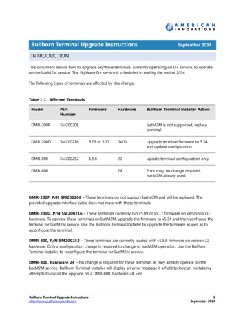
Installer’s GuideVariable Speed Air HandlersConvertible 2 — 5 0C42V41DATAM9A0C48V41DATAM9A0C60V51DAN o t e : “Graphics in this document are for representationonly. Actual model may differ in appearance.”N o t e : For use with BAYEA series heaters ONLYSAFETY WARNINGOnly qualified personnel should install and service the equipment. The installation, starting up, and servicing of heating, ventilating, andair-conditioning equipment can be hazardous and requires specific knowledge and training. Improperly installed, adjusted or alteredequipment by an unqualified person could result in death or serious injury. When working on the equipment, observe all precautions in theliterature and on the tags, stickers, and labels that are attached to the equipment.June 201718-GJ82D1-1B-EN
SAFETY SECTIONAIR HANDLERSI m p o r t a n t — This document contains a wiringdiagram, a parts list, and service information. This iscustomer property and is to remain with this unit.Please return to service information pack uponcompletion of work.WARNINGHAZARDOUS VOLTAGE!Failure to follow this Warning could result inproperty damage, severe personal injury, ordeath.Disconnect all electric power, including remotedisconnects before servicing. Follow properlockout/tagout procedures to ensure the powercannot be inadvertently energized.CAUTIONGROUNDING REQUIRED!Failure to inspect or use proper service tools mayresult in equipment damage or personal injury.Reconnect all grounding devices. All parts of thisproduct that are capable of conducting electricalcurrent are grounded. If grounding wires, screws,straps, clips, nuts, or washers used to complete apath to ground are removed for service, they mustbe returned to their original position and properlyfastened.WARNINGWARNINGPRESSURIZED REFRIGERANT!Failure to follow this Warning could result inpersonal injurySystem contains oil and refrigerant under highpressure. Recover refrigerant to relieve pressurebefore opening the system. Do no use nonapproved refrigerants or refrigerant substitutes orrefrigerant additives.CAUTIONSHARP EDGE HAZARD!Failure to follow this Caution could result inproperty damage or personal injury.Be careful of sharp edges on equipment or anycuts made on sheet metal while installing orservicing.I m p o r t a n t : Panel damage can occur with prolongedexposure to POE lubricants. Air handlerfront panels that come in contact with POEoil must be washed immediately withsoapy water.I m p o r t a n t : The TAM9 air handlers are only compatiblewith BAYEA** internal electric heaters.N o t e : Representative illustrations only included in thisdocument. Most illustrations display the upflowconfiguration.LIVE ELECTRICAL COMPONENTS!Failure to follow this Warning could result inproperty damage, severe personal injury, ordeath.Follow all electrical safety precautions whenexposed to live electrical components. It may benecessary to work with live electrical componentsduring installation, testing, servicing, andtroubleshooting of this product. 2016 Ingersoll Rand18-GJ82D1-1B-EN
Table of ContentsInstaller Guide Notes . . . . . . . . . . . . . . . . . . . . . . . 4Refrigerant Line Brazing . . . . . . . . . . . . . . . . . . . 24Unit Design. . . . . . . . . . . . . . . . . . . . . . . . . . . . . . . . . 5Condensate Drain Piping . . . . . . . . . . . . . . . . . . 28Unit Install Preparation . . . . . . . . . . . . . . . . . . . . . 7Electrical — Low Voltage . . . . . . . . . . . . . . . . . . 30Optional Accessories . . . . . . . . . . . . . . . . . . . . . . . 8Control Panel Reinstallation . . . . . . . . . . . . . . . 36Optional Cabinet Disassembly. . . . . . . . . . . . . . 9Electrical — High Voltage . . . . . . . . . . . . . . . . . . 37Placing Unit at Location . . . . . . . . . . . . . . . . . . . 13TAM9 OUTLINE DRAWING . . . . . . . . . . . . . . . . 40Unit Location Considerations . . . . . . . . . . . . . . 14Display Assembly / HumanInterface . . . . . . . . . . . . . . . . . . . . . . . . . . . . . . . . . . . 41Four-Way Conversion . . . . . . . . . . . . . . . . . . . . . 15Ducted and Non-Ducted ReturnApplications . . . . . . . . . . . . . . . . . . . . . . . . . . . . . . . 17Additional Unit PreparationConsiderations . . . . . . . . . . . . . . . . . . . . . . . . . . . . 18TAM9 — Technician Menu andConfiguration tree . . . . . . . . . . . . . . . . . . . . . . . . . 42Filters. . . . . . . . . . . . . . . . . . . . . . . . . . . . . . . . . . . . . . 47System Charge Adjustments . . . . . . . . . . . . . 47Setting the Unit — VerticalInstallation . . . . . . . . . . . . . . . . . . . . . . . . . . . . . . . . 19System Start Up . . . . . . . . . . . . . . . . . . . . . . . . . . . 48Setting the Unit — HorizontalInstallations . . . . . . . . . . . . . . . . . . . . . . . . . . . . . . . 21Abbreviations . . . . . . . . . . . . . . . . . . . . . . . . . . . 49Connecting the Duct work . . . . . . . . . . . . . . . . . 22TAM9 Sequence of Operation . . . . . . . . . . . . . 49Fault Reporting . . . . . . . . . . . . . . . . . . . . . . . . . . . . 51Checkout Procedures . . . . . . . . . . . . . . . . . . . . . . 52Refrigerant Line . . . . . . . . . . . . . . . . . . . . . . . . . . . 23Refrigerant System Layout . . . . . . . . . . . . . . . 2318-GJ82D1-1B-EN3
Installer Guide NotesALL Phases of this installation must comply withNATIONAL, STATE and LOCAL CODES!I m p o r t a n t : This Document is customer property and isto remain with t his unit. Please return toservice information upon completion ofworkI m p o r t a n t : These instructions do not cover allvariations in systems nor provide for everypossible contingency to be met inconnection with the installation. Shouldfurther information be desired or shouldparticular problems arise which are notcovered sufficiently for the purchaser’spurposes, the matter should be referred toyour installing dealer.See TAM9 Service Facts document for informationon reading the Display, Air Flow Tables andTroubleshooting Flowcharts.I m p o r t a n t : The low voltage wire harness is shipped inthe supplied document pack.N o t e : The manufacturer recommends installing ONLYA.H.R.I. approved, matched indoor and outdoorsystems. Some of the benefits of installingapproved matched indoor and outdoor splitsystems are maximum efficiency, optimumperformance, and the best overall systemreliability.N o t e : Condensation may occur on the surface of the airhandler when installed in unconditioned spaces,verify that all electrical and refrigerant linepenetrations on the air handler are sealedcompletely.The TAM9 air handlers will only use the followinginternal electric K1BAYEAAC10BK1N o t e : Duct heaters cannot be applied with this airhandler.N o t e : The heater size needs to be configured in theConfiguration Menu.418-GJ82D1-1B-EN
Unit DesignTable 1. Cabinet PenetrationImportant: Due to the unique design of this unit, which allows theelectrical wiring to be routed within the insulation, do notscrew, cut, or otherwise puncture the unit cabinet in anylocation other than the ones illustrated.Important: Under no conditions should metal strapping be attachedto the unit to be used as support mechanisms forcarrying or suspension purposes.Table 2. Panel RemovalThe unit contains four (4) access panels: Blower/Filter, Coil, Line Set,and Heater.The Blower/Filter panel is removed using 1/4 turn thumb screws.1.Turn thumb screws on Blower/Filter panel.2.Pull top of panel out, away from cabinet.3.Lift panel up out of channel.4.Set aside.18-GJ82D1-1B-EN5
Unit DesignThe Coil, Line Set, and Heater panels are removed using Phillips headscrews.Removal requires #3 Size PhillipsCoil and Heater panels must be removed prior to removing the LineSet panel.To remove Coil Panel:1.Turn screws on Coil panel.2.Rotate bottom of panel away from cabinet.3.Disconnect the plug from the door to the unit.4.Remove panel from channel.5.Set aside.To remove Heater Panel:1.Turn screws on Heater panel.2.Pull panel straight out, away from cabinet.3.Set aside.Removal of the Line Set panel is required for all refrigerant line brazingand some condensate line assembly depending on your orientation.To remove Line Set panel:1.Remove both Heater and Coil panels.2.Turn screws on Line Set panel.3.Pull panel straight out, away from cabinet.4.Set aside.Note: After replacing all panels, loosen the Line Set panel screwsapproximately 1/4 — 1/2 turn. This will improve the sealbetween the Heater Panel and Line Set panel.618-GJ82D1-1B-EN
Unit Install Preparation1.Check for damage and report promptly to the carrier any damagefound to the unit.Note: If the unit must be transported in a horizontal position, it mustbe laid on its back (marked “REAR” on carton).Note: After unit is removed from the carton, verify coil is pressurized.Carefully remove the liquid line plug. If no pressure is released,check for leaks.Note: Remove the cardboard from the bottom of the blower. Cut thetie wrap and remove the foam shipping block located at themotor.18-GJ82D1-1B-EN7
Optional AccessoriesAccessory NumberElectric Heater, 4kW, Breaker, 24V Control, 1 PhElectric Heater, 4kW, Lugs, 24VControl, 1 PhElectric Heater, 5kW, Breaker, 24V Control, 1 PhElectric Heater, 5kW, Lugs, 24VControl, 1 PhElectric Heater, 8kW, Breaker, 24V Control, 1 PhElectric Heater, 8kW, Lugs, 24VControl, 1 PhElectric Heater, 10kW, Breaker, 24V Control, 1 PhElectric Heater, 10kW, Lugs, 24VControl, 1 PhElectric Heater, 15kW, Breaker, 24V Control, 1 PhElectric Heater, 20kW, Breaker, 24VControl, 1 PhElectric Heater, 25kW, Breaker, 24V Control, 1 PhElectric Heater, 10kW, Lugs, 24VControl, 3 PhElectric Heater, 15kW, Lugs, 24V Control, 3 PhSupply Duct Flange ASupply Duct Flange BSupply Duct Flange CReturn Duct Flange AReturn Duct Flange BReturn Duct Flange ASETAMABAYBAFKT175A (d)BAYBAFKT215A (d)BAYBAFKT235A (d)TASSBK175 (b)(e) (f)TASSBK210 (b)(e)(f)TASSBK235 (b)(e)(f)Side Return Kit with 16” x 20” FilterFront Return Kit for 17.5” CabinetFront Return Kit for 21.0” CabinetFront Return Kit for 23.5” CabinetDownflow Sub-Base KitSound Baffle Kit for 17.5” CabinetSound Baffle Kit for 21.0” CabinetSound Baffle Kit for 23.5” CabinetSound Baffle Kit for 17.5” CabinetSound Baffle Kit for 21.0” CabinetSound Baffle Kit for 23.5” CabinetInternal Condensate Switch KitHorizontal Hanger KitUVC LightsLow Voltage Conduit Entry KitSingle Power Entry KitHydronic Coil — 50,000 BTUH — Slide-inHydronic Coil — 70,000 BTUH — Slide-inHydronic Coil — 80,000 BTUH — Slide-inHydronic Coil — 100,000 BTUH — Add onHydronic Heater Relay Kit — (used in Communicating mode only)Solcoustic Liner Kit for 17.5” cabinetSolcoustic Liner Kit for 21.5” cabinetSolcoustic Liner Kit for 23.5” cabinet3/4” PVC Threaded Pipe Kit foam Seal (10 per box)EMI/EFI Air Handler Electronic noise kit for variable speed blower 5SB (b) (c)TASB215SB (b)(c)TASB235SB (b)(c)Side Return KitHigh Velocity Filter Kit, 16” x 20” x 1” (10 filters)High Velocity Filter Kit, 20” x 20” x 1” (10 filters)High Velocity Filter Kit, 22” x 20” x 1” (10 filters)Plenum Stand with integrated sound baffle APlenum Stand with integrated sound baffle BPlenum Stand with integrated sound baffle CFits Cabinet Size(a)A to CA to CA to CA to CA to CA to CA to CA to CB to CCCA to CB to CABCABCA to CABCABCA to CABCA to CABCABCA to CA to CA to CA to CA to CA to AB to BC to CC to CA to CABCA to CA to CA Cabinet is 17.5” wide, B Cabinet is 21.5” wide, C Cabinet is 23.5” wide.Contact your distributor for information.In open air applications, the plenum stand with sound baffle provides sound reduction.Mounts inside air handler filter channel.In return plenum applications, use TASSBK for sound reduction.Mounts to TASB original plenum stand without integrated baffle.18-GJ82D1-1B-EN
Optional Cabinet DisassemblyNote: If the unit must be transported in a horizontal position, it must belaid on its back (marked “REAR” on carton).Note: To reassemble cabinet, follow the steps in reverse order. Ensureelectrical connections are secure and the plug clips are engaged.1.Remove all four front panels.2.Remove the two screws on the seal bar and pull the seal barstraight out.3.Disconnect all wiring connections routed to the blower assembly.4.Slide Blower assembly out of unit using built-in blower supportchannels and set aside.Note: Remove the cardboard from the bottom of the blower. Cut thetie wrap and remove the foam block located at the motor.5.Disconnect wires to the EEV motor and sensors. Cut the wire ties onthose wire harnesses if necessary and replace after re-installing.Note: If cut, wire ties that held the sensor must be replaced after the coil isplaced back into the cabinet.18-GJ82D1-1B-EN9
Optional Cabinet Disassembly6.Slide Coil assembly out of unit using built-in coil support channelsand set aside7.Use a 5/16 Allen wrench on the locking mechanism on each sideof the bottom half of the cabinet to loosen the locking mechanism.The locks loosen by turning counter-clockwise approximately 3/4of a turn.1018-GJ82D1-1B-EN
Optional Cabinet Disassembly8.Lift the Coil section up and away from the Blower section. Setaside.Note: When separating the two cabinet pieces, make sure the gasketremains intact.18-GJ82D1-1B-EN11
Optional Cabinet Disassembly9.For extremely tight spaces where the cabinet needs to be rotatedthrough a small opening, remove the top panel and all crossmembers. Use a manual driver to avoid stripping screw holes.10. Continue preparation by following the proper carrying procedures shown in the next section.1218-GJ82D1-1B-EN
Placing Unit at Location1.Carry the unit to the installation location2.Reassembly by reversing the steps listed in Section 4 ifdisassembly was required. If cut, wire ties that held the sensorwiring must be replaced.Important: Under no conditions should metal strapping be attachedto the unit to be used as support mechanisms for carryingor suspension purposes.Approved Carrying: Hold by the cross members within the cabinet or unit top plate anduse as handles for lifting and carrying the coil and blower sections.18-GJ82D1-1B-EN13
Unit Location ConsiderationsTable 3. Unit Dimensions and WeightMODEL NUMBERHxWxD(inches)Coil and HeaterCompartmentHeight *(inches)Unit Net Weight(pounds)TAM9A0A24V21DA49.9 x 17.5 x 21.828.1120TAM9A0B30V31DA55.7 x 21.3 x 21.833.9133TAM9A0C36V31DA56.9 x 23.5 x 21.835.1143TAM9A0C42V41DA56.9 x 23.5 x 21.835.1158TAM9A0C48V41DA61.7 x 23.5 x 21.839.9174TAM9A0C60V51DA61.7 x 23.5 x 21.839.9178WH* Blower compartment height is 21.8 inches.D1418-GJ82D1-1B-EN
Four-Way ConversionTo place the unit in the configuration your application requires (upflow, downflow, horizontal right, or horizontal left), simply turn the unit tothat orientation. Remember to adjust the badge accordingly.Note: The air handlers are shipped from the factory suitable for four-way application.Note: Entry for low voltage connections is allowed on either side of cabinet.18-GJ82D1-1B-EN15
Four-Way Conversion1618-GJ82D1-1B-EN
Ducted and Non-Ducted Return ApplicationsTable 4. Non-Ducted ApplicationsCAUTIONHAZARDOUS VAPORS!Failure to follow this Caution could result inproperty damage or personal injury.Hazardous vapors can be distributed throughout theconditioned space and equipm ent damage canresult. Do not install an air handler with a nonducted return in the same closet, alcove, or utilityroom as a fossil fuel device.Non-Ducted Return Installations: Installation in a closet, an alcove, or a utility room without areturn duct requires the use of a plenum accessory kit as it usesthe area space as a return air plenum. Minimum clearances tocombustible materials and service access must be observed (seeoutline drawing). This area may also be used for other purposes, including anelectric hot water heater, but in no case shall a fossil fuel device beinstalled and/or operated in the same closet, alcove, or utilityroom. Review local codes to determine limitations if the unit is installedwithout a return air duct.Table 5. Ducted Return Installations.Ducted Return Installations: Installation in an attic, garage, or crawl space with ducted supplyand return air is appropriate. Minimum clearances to combustiblematerials and service access must be observed (see outlinedrawing).18-GJ82D1-1B-EN17
Additional Unit Preparation ConsiderationsFor proper installation the following items must beconsidered prior to moving the unit to its installationsite: Consider the overall space needed when externalaccessories are used, additional height and widthrequirements may exist. Pursuant to Florida Building Code 13–610.2A.2.1,this unit meets the criteria for a factory sealed airhandler. These units are not approved for outdoorinstallation. If a side return is needed for your application, theside return MUST be prepared prior to moving theair handler to its installation location. See the SideReturn Kit #BAYSRKIT100A Installer Guide fordetailed instructions, if used.These units must be installed in the proper air flowdirection. Any third-party heater accessories or hydronic coilsmust be downstream of the unit. 18When the air handler is located adjacent to theliving area, the system should be carefully designedwith returns which minimize noise transmissionthrough the return air grill. Although the air handleris designed with large blowers operating atmoderate speeds, any blower moving a highvolume of air will produce audible noise whichcould be objectionable when the unit is located veryclose to a living area. It is often advisable to routethe return ducts under the floor through the attic.Such design permits the installation of air returnremote from the living area (i.e. central hall).Study the unit’s outline drawing and dimensionsprior to selecting the installation site. Note inadvance which electrical conduit entry points andcondensate drain holes are to be used, so thatproper clearance allowances can be made forinstallation and future maintenance.Installation of the air handler must be made prior to, or at the same time as, the installation of theoutdoor unit in order to allow access for refrigerantlines.N o t e : No atomizing style humidifier is allowed in thereturn plenum with the use of this unit. Excessive bypass air may cause water blow-off,which will adversely affect system operation and aircleaner performance. To verify bypass airflow,follow the Bypass Humidifier Pre-InstallationCheckout and Set-Up Procedures available throughyour local distributor. Ask for publication number18–CH37D1–* Steam and Flow-through Fan PowerDuct-mounted Humidifiers. Follow the humidifierinstallation instructions. These should only beinstalled on the supply air side of the system.N o t e : The air handlers have been evaluated inaccordance with the Code of Federal Regulations,Chapter XX, Part 3280 or the equivalent.“SUITABLE FOR MOBILE HOME USE.”Note: This unit is certified to UL 1995. The interiorcabinet wall meets the following:— UL94–5VA Flame Class Listed— UL723 Steiner Tunnel Listed for 25/50 Flame/Smoke— UL746C Listed for Exposure to Ultraviolet Light,Water Exposure and Immersion18-GJ82D1-1B-EN
Setting the Unit — Vertical InstallationTable 6. ConsiderationsProvide a minimum height of 14 inches for proper unrestricted airflowbelow the unit. Allow a minimum of 21 inches clearance in front of theair handler to permit maintenance and removal of filter. Position unit on suitable foundation. If a manufacturer approvedaccessory is not used, a frame strong enough to support the totalweight of the unit, accessories, and duct work must be provided. Isolate unit from the foundation using a suitable isolatingmaterial.Note: The following sound insulation kits are available to lessenobjectionable sound.BAYINSKT175A for use with 17.5” cabinetsBAYINSKT215A for use with 21.5” cabinetsBAYINSKT235A for use with 23.5” cabinetsTypical Closet InstallationTable 7. Upflow InstallationTASB Installation1.Install the TASB plenum stand with integrated sound baffle usingthe TASB instructions.Note: Kit is used for open air applications.TASB175SB for use with 17.5” cabinetsTASB215SB for use with 21.5” cabinetsTASB235SB for use with 23.5” cabinetsMITISRKIT1620 — Side return kit with 16” x 20” filterContact your distributor for more information.Note: The following sound insulation kits are available to lessenobjectionable sound.BAYINSKT175A for use with 17.5” cabinetsBAYINSKT215A for use with 21.5” cabinetsBAYINSKT235A for use with 23.5” cabinetsAirflowAirflowowrflAiTypical TASB Installation18-GJ82D1-1B-EN19
Setting the Unit — Vertical InstallationTable 8. Plenum Installation2.Assemble the plenum using the plenum’s Installer Guide.On units with sheet metal returns: Return plenum must be flanged.Sheet metal drill point screws must be 1/2” in length or shorter.AirflowTypical Plenum InstallationTable 9. Downflow Installation Downflow installation must comply with national, state, and localcodes.3.Prepare the location site as appropriate for your application andper national, state, and local code requirements.4.Set the unit in position.Typical Downflow Installation2018-GJ82D1-1B-EN
Setting the Unit — Horizontal InstallationsTable 10.ConsiderationsImportant: Due to the unique design of this unit, which allows theelectrical wiring to be routed within the insulation , do notscrew, cut, or otherwise puncture the unit cabinet in anylocation other than the ones illustrated in this InstallerGuide or in an approved accessory’s Installer Guide.Field SuppliedIsolatorsImportant: Make certain that the unit has been installed in a levelposition to ensure proper draining.Important: Under no conditions should metal strapping be attachedto the unit to be used as support mechanisms forcarrying or suspension purposes.1.Support the unit from the bottom (near both ends). The serviceaccess must remain unobstructed.a.Approved bottom support methods are rail, u-channels(Unistrut ), or other load bearing materials.b.The unit must be isolated carefully to prevent soundtransmission. Field supplied vibration isolators arerecommended.Important: The unit can only be supported from the bottom unlessusing kit BAYHHKIT001A. Do not drill or screw supportsinto any area of the cabinet.Note: Do not allow the unit to be used as strain relief.2.Install an auxiliary drain pan under the horizontal air handler toprevent possible damage to ceilings.a.Isolate the auxiliary drain pan from the unit and from thestructure.b.Connect the auxiliary drain pan to a separate drain line andterminate according to local codes.18-GJ82D1-1B-ENAuxiliary DrainPanBottom SupportNear Both EndsNote: BAYHHKIT001A Hanging Bracket Kit may be orderedseparately.Important: The BAYHHKIT001A may not be used if the cabinet hasbeen altered per Installer Guide 18–GJ58D1–121
Connecting the Duct workTable 11.Duct Connection ConsiderationsImportant: Due to the unique design of this unit, which allows theelectrical wiring to be routed within the insulation, do notscrew, cut, or otherwise puncture the unit cabinet in anylocation other than the ones illustrated in this InstallerGuide or in an approved accessory’s Installer Guide.Important: Under no conditions should metal strapping be attachedto the unit to be used as support mechanisms forcarrying or suspension purposes.Important: On units with sheet metal returns: Return air plenummust be flanged. Sheet metal drill point screws must be1/2” in length or shorter. The supply and return air ducts must be connected to the unitwith non flammable duct connectors. See the Outline drawing for sizes of the duct connections. After the ducts are secured, seal around the supply and returnducts to prevent air leakage. Insulate all duct work that will be outside of conditioned spaces. Convertible Duct Flange Kits are available to connect the supplyplenum or for mounting on the discharge opening to provide a“flush fit” for 1–1/2” duct board applications. If front or rear return is required, the air handler must be elevated— placed on a pedestal or plenum and duct must be connected tothis pedestal or plenum. If side return is required, the Side Return Kit # BAYSRKIT100Aaccessory must be used. A remote filter will be required. To ensure maximum efficiency and system performance, theexisting supply and return duct system static pressures must notexceed the total available static pressure of the air handler.Reference ACCA Manual D, Manual S and Manual RS along withthe air handler Product Data and Service Facts for additionalinformation.Note: Side return is not approved without Side Return Kit #BAYSRKIT100. More than one Side Return Kit may benecessary depending on the application. Refer to theInstallation Guide in BAYSRKIT100 for approved ductconnections, sizing, number, transitions, and accessoryapplication.Note: Duct work must be supported as appropriate. See National andlocal codes for guidelines. Do not depend on the unit to supportduct work.2218-GJ82D1-1B-EN
Refrigerant LineTable 12.Refrigerant Line Connection SizesModelVapor Line ConnectionLiquid Line 41DA7/83/8TAM9B0C60V51DA7/83/8Notes:1.This table indicates the tubing connection diameters at the indoor coil. A field supplied reducing coupling may be required.2.All AHRI listed systems are tested with 25 feet of refrigeration tubing; the rated tubing diameters are located in the electronic performancedata system.3.If the refrigeration lines exceed 60 feet in linear length and/or if alternate size refrigeration tubing is present at the job, please consult SSAPG006–EN or 32–3312** (latest version)Refrigerant System Layout18-GJ82D1-1B-EN23
Refrigerant Line BrazingTable 13.1.Braze the Refrigerant LinesRemove Heater, Coil, and Line Set panels.Important: Do NOT unseal coil refrigerant connection stubsuntil ready to make connections.Important: Heat Sensitive Sensors. The Gas TemperatureSensor must be removed or a wet rag must bewrapped around the suction line between theSensor and the braze joint to protect it fromfailure due to overheating.2.Remove the sealing plug from the indoor coil suctionline.3.Remove the sealing plug from the indoor coil liquid line.This coil is pressurized with 8–12 psig of dry air. Do notstand directly in front of the coil connections when removingsealing plugs.2418-GJ82D1-1B-EN
Refrigerant Line BrazingTable 13.4.Braze the Refrigerant Lines (continued)Connect, but do not braze field line set to indoor coil.a.Allow a minimum of 1.5 inches of refrigerant line setbefore using an elbow coupling.1.5” MINImportant: Service access to the auxiliary heater mustremain unobstructed.Important: Heat Sensitive Sensor. The temperature Sensor must beremoved or a wet rag must be wrapped around thesuction line between the Sensor and the braze joint toprotect the Sensor from failure due to overheating.5.Braze refrigerant line connections.a.Pull back the insulation before brazing the suction line.b.Wrap the Gas Temperature Sensor (GT) with a wet rag.c.Braze the refrigerant line connections.Important: Care must be taken during brazing to avoid damage tounit components and wiring.Note: The suction line must be insulated prior to brazing the line setto the air handler stubs.18-GJ82D1-1B-EN25
Refrigerant Line Brazing6.Pressurize the refrigerant lines and evaporator coil to 150 PSIGusing dry nitrogen.7.Check for leaks by using a soapy solution or bubbles at eachbrazed location.Important: Do not open the service valves until the refrigerant linesand indoor coil leak check and evacuation are complete.8.Evacuate until the micron gauge reads no higher than 350microns, then close off the valve to the vacuum pump.0350MicronsON9.OFFObserve the micron gauge. Evacuation is complete if the microngauge does not rise above 500 microns in one (1) minute.a.Once evacuation is complete blank off the vacuum pump andmicron gauge, and close the valves on the manifold gaugeset.1 MIN.Note: Charge system using Outdoor unit’s Installer Guide or ServiceFacts.Note: Use soapy water to wipe any refrigerant oil off the panels.2618-GJ82D1-1B-EN
Refrigerant Line Brazing10. Replace the Line Set panel.a.Allow time for tubing to cool.b.Install grommets to line set piping in orientation shown.Note: A slight amount of dish soap can be used to aid in theinstallation of the grommets. Remove any excess from thetubing and grommet after the grommet is installed.c.Slide the bottom of the Line Set panel down over therefrigerant lines and grommets. The grommets will seal theline openings.d.Tighten screws on the Line Set panel.SEE ENLARGEDILLUSTRATION FOR ORIENTATION18-GJ82D1-1B-EN27
Condensate Drain PipingCondensate Drain Piping Considerations Condensate drain plumbing must comply with national, state, andlocal codes. Route condensate drain lines away from air handler so they do notinterfere with access panels. Slope the drain lines downward a minimum of 1/4” per foot,support per local codes. Do not use reducing fittings in the condensate drain lines. Do not connect the drain line to a closed drain system. Do not use a torch or flame near the plastic drain pan coupling. A P-trap is not required for proper drainage due to the positivepressure of the air handler; howeve
2016 Ingersoll Rand 18-GJ82D1-1B-EN SAFETY SECTION AIR HANDLERS Important — This document contains a wiring diagram, a parts list, and service information. This is customer property and is to remain with this unit.