Transcription
MEN -002-BGARAGE DOOR MENOPENER-002-BINSTALLATION MANUALGARAGE DOOR ON MANUALPlease read the manual and the enclosed safety materialscarefully!Fasten the manual near the garage door after installation.Periodic checks of the opener are required to ensure safeoperation.The model number label is located on the left side panelof your opener.Please read the manual and the enclosed safety materialscarefully!Fasten the manual near the garage door after installation. Pleasereadof themanualthe toenclosedPeriodicchecksthe openerare andrequiredensure safesafetymaterialscarefully!operation. Fastenthe manualnearthe garagedoorThemodel numberlabel islocatedon the leftsideafterpanelof your installation.opener. Periodic checks of the opener are required toensure safe operation.The model number label is located on the leftside panel of your opener.
TABLE OF CONTENTSINTRODUCTION.3Tools needed.5Assemble the Rail.6Garage door opener assembly.10Hardware.10Fasten the Rail to the garage door opener.12Determine the Header Bracket Location.13Install the Header Bracket.15Connect the Rail to the Header Bracket.17Position the garage door opener.18Hang the garage door opener.19Attach the Emergency Release Rope and Handle.20Install the door bracket.21Connect the door arm to the trolley.23Install the Wall Control.25Attach the Warning Labels.28Install The Photo Eye Safety System.29Power and adjustments.33Programming and adjustment.34Programming buttons.34Preparation.34Connect Power.34Program the travel.35Remote Control.36To Erase the Memory.37The adjustment of reverse force.38Circuit board.40Use photoelectric switches.41Turn off light automatically.42Power failure clutch lock.42Backup battery.42Door within a Door.43Maintenance and repair.43Technical parameter.43Trouble shooting.442
INTRODUCTIONSafety Symbol and Signal Word ReviewThis garage door opener has been designed and tested to offersafe service provided it is installed, operated, maintained andtested in strict accordance with the instructions and warningscontained in this manual. When you see these Safety Symbols andSignal Words on the following pages, they will alert you to thepossibility of serious injury or death if you do not comply with thewarnings that accompany them.The hazard may come from something or from electric shock. Readthe warnings carefully.When you see this Signal Word on the following pages, it will alertyou to the possibility of damage to your garage door and/or thegarage door opener if you do not comply with the cautionarystatements that accompany it. Read them carefully.Check your garage door1. Disable locks and remove any ropes connected to thegarage door.2. Lift the door halfway up. Release the door. If balanced, itshould stay in place, supported entirely by its springs.3. Raise and lower the door to check for binding or sticking. Ifyour door binds, or is out of balance, call a trained doorsystems technician.4. Check the seal on the bottom of the door. Any gapbetween the floor and the bottom of the door must notexceed 1/4 inch (6 mm). Otherwise, the safety reversalsystem may not work properly.3
5. The opener should be installed above the center of thedoor. If there is a torsion spring or center bearing plate inthe way of the header bracket, it may be installed within 4feet (1.2 m) to the left or right of the door center. SeeInstalling the Header Bracket section.4
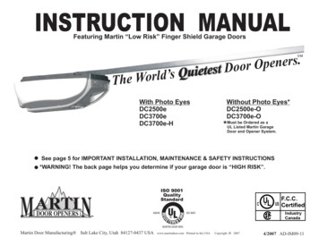
Tools neededDuring assembly, installation and adjustment of the opener,instructions will call for hand tools as illustrated below.5
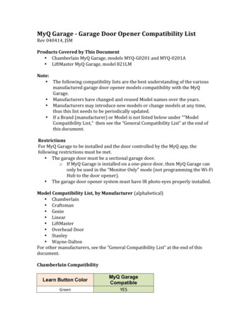
1、Assemble the RailTo avoid installation difficulties, do not run the garage door openeruntil instructed to do so.NOTE: If you choose the Three-pieces Sectional Rail, you mayneed the following installation instructions.Rail Accessories6
Assemble the Rail7
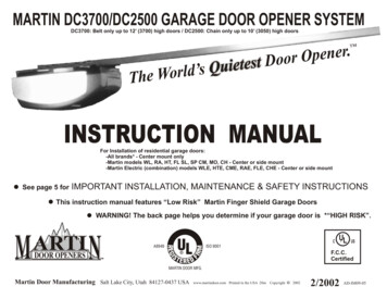
Assemble the vethe three rail sections and place them ionsandandplaceplace themthem Removefloor.floor.floor.Three holesholes railrailThreeThreeholes railCenter railrailCenterCenterrailSeven holes railSeven holes rail1.2、Rail ��Spread carefullycarefully thethe chain/beltchain/belt straightstraight insideinside thethe rail.rail. CheckCheck1.3、Spread1.3、Spreadcarefullythe chain/beltstraightinside therail. idethe rail.to bebe suresure thethe chainchain isis notnot twisted.twisted.toCheckto thebe chainsure thechainis not twisted. Note: Make sure thetobe sureis nottwisted.Note: MakeMake suresure thethe chainchain engageengage thethe 10-tooth10-tooth sprocketsprocket asas esurethethe10-toothchain engagethe as10-toothsprocket asshown.6668
Assemble the RailRailAssembly1.4Screwand lock washer installation.1.4、Screw and lock washer installation.Rail Assembly(2)1.4、Screwand lock washerA6installation.RailAssembly1.4、Screw and lock washer 1.5.1 To increase the tension and tighten the chain, turn the tension1.5.1 To increasethe tension and tighten the chain, turn the1.5、Tightenthe Chainor adjustable wrench until the nut is spacednut clockwisetension nut clockwise or adjustable wrench until the nut is spaced1.5、Tightenthefromtherailend1.5.1 Toproperlyincreasetheendtensionand-plate.tighten the chain, turn the thenutadjustableis untilthenut turnis chain,thetension will1.5.2 gwillovertightentheadjustablechainmay causedamagethe system.properlyfrom therailendand-plate.nutclockwiseorwrenchuntil thenut istospacedover tighten the chain and may cause damage to the system.1.5.3To theloosetension,turn nut counterclockwise.1.5.2Oncenuttheis spacedany additional tightening willproperlyfromrail end correctly,-plate.tightenthechainandmaydamageto thesystem. will1.5.2overthenuttension,is Totightenloose thetension,turnnutcounterclockwise.the chain and may cause damage to the system.1.5.3 To loose the tension, turn nut counterclockwise.25mm25mmNote: the trolley should be away from locking holes.Note: the trolley should be away from uldshouldbebeawayawayfromlockingholes.Note: thefromlockingholes.Locking HolesLocking Holes7977
Garage door opener assemblyHardware10
Garage door opener assembly11
Garage door opener assembly1、Fasten the Rail to the garage door opener1.1 Place the opener on cardboard or protective surface on floor soopener does not get scratched. Chassis side of opener isfacing up.1.2 Position rail onto opener chassis by lining up rail sprocket,Make sure shaft insert into rail sprocket. Press rail down firmlyonto shaft and opener chassis. DO NOT HAMMER.1.3 Position 2 “U” rail clips over rail and onto chassis. Insert selfthreading screw (4) (H12) through rail clips holes and intochassis holes. and tighten self-threading screws firmly to holdrail to the garage door opener head.Note: To avoid SERIOUS damage to garage door opener, useONLY those bolts/fasteners mounted in the top of the opener.12
Garage door opener assembly2、Determine the Header Bracket LocationInstallation procedures vary according to garage door types. Followthe instructions which apply to your door.2.1 Close the door and mark the inside vertical centerline of thegarage door.2.2 Extend the line onto the header wall above the door.You can fasten the header bracket within 4 feet (1.22 m) of theleft or right of the door center only if a torsion spring or centerbearing plate is in the way; or you can attach it to the ceilingwhen clearance is minimal. (It may be mounted on the wallupside down if necessary, to gain approximately 1/2" (1 cm).If you need to install the header bracket on a 2x4 (on wall orceiling), use lag screws (not provided) to securely fasten the 2x4 tostructural supports.2.3 Open your door to the highest point of travel as shown. Drawan intersecting horizontal line on the header wall above the highpoint: 2" (5 cm) above the high point for sectional door with track.NOTE: If the total number of inches exceeds the height available inyour garage, use the maximum height possible.13
Garage door opener assembly14
3、Install the Header Bracket You can attach the header bracketeither to the wall above the garage door, or to the ceiling. Followthe instructions which will work best for your particularrequirements. Do not install the header bracket over drywall. Ifinstalling into masonry, use concrete anchors (not provided).Option A WALL INSTALLATION3.1A Center the bracket on the vertical centerline with the bottomedge of the bracket on the horizontal line as shown (with the arrowpointing toward the ceiling).3.2A Mark the holes. Drill 3/16" pilot holes and fasten the bracketsecurely to a structural support with the hardware provided.15
Option B CEILING INSTALLATION3.1B Extend the vertical centerline onto the ceiling as shown.3.2B Center the bracket on the vertical mark, no more than 6" (15cm)3.3B from the wall. Make sure the arrow is pointing away from thewall. The bracket can be mounted flush against the ceiling whenclearance is minimal.3.4B Mark the holes. Drill 3/16" pilot holes and fasten bracketsecurely to a structural support with the hardware provided.16
4、Connect the Rail to the Header BracketAlign the rail to the header bracket, fasten with the bolts and nuts(H1) (H2) as shown below.HARDWAREB5 Cotter Pin Φ2 25(1)17B6 Shouldered shaft, long Φ8 80(1)
5、Position the garage door openerNOTE: A 2x4 is ideal for setting the distance between the rail andthe door. If the ladder is not tall enough you will need help at thispoint.If the door hits the trolley when it is raised, pull the trolley releasearm down to disconnect the chain connector kit and trolley. Slidethe trolley toward the garage door opener. The trolley can remaindisconnected until further instruction.18
6、Hang the garage door opener19
7、Attach the Emergency Release Rope and HandleNOTE: If it is necessary to cut the emergency release rope, sealthe cut end with a match or lighter to prevent unraveling. Ensurethat the emergency release rope and handle are above the top ofall vehicles to avoid entanglement.7.1 Insert one end of the emergency release rope through thehandle. Tie a knot at least 1 inch (2.5 cm) from the end of theemergency release rope.7.2 Insert the other end of the emergency release rope through thehole in the trolley release arm. Make sure the handle is 6 feet (1.83m) above the floor and secure with a knot.20
8、Install the door bracketFigure 1 shows one piece of angle iron as the horizontal brace. Forthe vertical brace, 2 pieces of angle iron are used to create a Ushaped support. The best solution is to check with your garagedoor manufacturer for an opener installation door reinforcement kit.NOTE: Many door reinforcement kits provide for direct attachmentof the clevis pin and door arm. In this case you will not need thedoor bracket; proceed to the next step.21
A horizontal and vertical reinforcement is needed forlightweight garage doors (fiberglass, aluminum, steel, doorswith glass panel, etc.) (not provided). A horizontalreinforcement brace should be long enough to be secured totwo or three vertical supports. A vertical reinforcement braceshouldcovertheheightofthetoppanel.Option SECTIONAL DOORS8.1 Center the door bracket on the previously marked verticalcenterline used for the header bracket installation. Note correct UPplacement, as stamped inside the bracket.8.2 Position the top edge of the bracket 2"-4" (5-10 cm) below thetop edge of the door, OR directly below any structural supportacross the top of the door.8.3 Mark, drill holes and install as follows, depending on yourdoor’s construction:Metal or light weight doors using a vertical angle iron bracebetween the door panel support and the door bracket:· Drill 3/16" fastening holes. Secure the door bracket using the twoself-threading screws (C2). (Figure 2)· Alternately, use two 5/16" bolts, lock washers and nuts (notprovided). (Figure 3)22
9、Connect the door arm to the trolleyHARDWAREOption SECTIONAL DOORS NOTE: If the holes in the curveddoor arm and the straight door arm do not align, reverse thestraight door arm, select two holes (as far apart as possible) andattach using bolts (H4) and nuts (H3).9.1239.2
9.2 Attach the curved door arm tothe door bracket using theshouldered shaft (H2). Attach withthe cotter (H5).9.49.5 Pull the emergency release handle toward the chain/beltconnector until they are connected, you will hear a click.NOTE: If the straight door arm is hanging down too far, you maycut 6 inches (15 cm) from the solid end.24
10、Install the Wall ControlINTRODUCTIONInstall the wall control within sight of the door at a minimum heightof 5 feet (1.5 m) where small children cannot reach, and away fromthe moving parts of the door. Your product may look different thanthe illustrations.NOTE: For gang box installations it is not necessary to drill holes orinstall the drywall anchors. Use the existing holes in the gang box.25
abc26
caWALL CONTROL BATTERY REPLACEMENTaaba27
11、 Wire the wall control to the garage door opener11.1 Strip 7/16 inch (11 mm) of insulation from one end of the wireand separate the wires.11.2 Connect the white wire to the GND terminal and the red\whitewire to the PBSW terminal on garage door opener.28
12、 Attach the warning labels12.1 Attach the entrapment warning label on the wall near the doorcontrol with tacks or staples.12.2 Attach the manual release/safety reverse test label in a visiblelocation on the inside of the garage door.Install the Photo Eye Safety SystemIntroductionIMPORTANT INFORMATION ABOUT THE SAFETY REVERSINGSENSOR The safety reversing sensor must be connected andaligned correctly before the garage door opener will move inthe down direction.29
The sending sensor (with a red LED) transmits an invisible lightbeam to the receiving sensor (with a green LED). If an obstructionbreaks the light beam while the door is closing, the door will stopand reverse to the full open position, and the garage door openerlights will flash three minutesNOTE: For energy efficiency the garage door opener will entersleep mode when the door is fully closed. The sleep mode shutsthe garage door opener down until activated. The sleep mode issequenced with the garage door opener light bulb; as the light bulbturns off the sensor LEDs will turn off and whenever the garagedoor opener lights turn on the sensor LEDs will light. The garagedoor opener will not go into the sleep mode until the garage dooropener has completed 5 cycles upon power up.When installing the safety reversing sensors check thefollowing:· Sensors are installed inside the garage, one on either side of thedoor.· Sensors are facing each other with the lenses aligned and thereceiving sensor lens does not receive direct sunlight.· Sensors are no more than 6 inches (15 cm) above the floor andthe light beam is unobstructed.30
Install the Photo Eye Safety System 1、Install the SafetyReversing SensorsThe safety reversing sensors can be attached to the wall, Thesensors should be no more than 6 inches (15 cm) above the floor.Position the mounting bracket against the wall with the curved armsfacing the door. Make sure there is enough clearance for the beamto be unobstructed. Attach the mounting bracket to the wall usinglag screws.Wire the Safety Reversing SensorsStrip 7/16 inch (11 mm) of insulation from each set of wires.Separate the wires. Twist the white wires together. Twist thewhite/red wires together.31
Insert the white wires into the GND terminal on the garage dooropener. Insert the white/red wires into the PB terminal on thegarage door opener.Ensure the Safety Reversing Sensors are aligned The door willnot close if the sensors have not been installed and alignedcorrectly.When the light beam is obstructed or misaligned while the door isclosing, the door will reverse and the garage door opener lights willflash three minutes. If the door is already open, it will not close.Check to make sure the LEDs in both sensors are glowing steadily.The LEDs in both sensors will grow steadily if they are aligned andwired correctly.32
PowerConnect power33
Adjustments34
Programming and adjustmenta) Programming buttonsb) Preparation:Move the door to lock the trolley so that the opener candrive the door when adjustment.c) Connect Power:Puts through the power source, the LED display from “9” to“1”.If the number direction displayed on LED is opposite, pressbutton “SETTING”, the LED displayed would be inverted,then display again from “9” to “1”.35
d) Program the travelNOTE: The UP and DOWN Buttons can be used to move the doorup and down as needed.36
e) Remote ControlPROGRAM A REMOTE USING THE CODE BUTTONNote: Repeat up steps to code a maximum of 20 different remotecontrols.To open or close the garage door, press and hold button. When thegarage door move, release button. To stop garage door duringtravel, press and hold button until door stops, the release button.To resume garage door travel after stopping, press button again.Door begins to move in the opposite direction.37
f)To Erase the MemoryPress and hold the CODE button on garage door opener, the “ ”will turn on. Release the CODE button when the “ ” turns off. Allremote control are now erased. Reprogram any accessory youwish to use.38
g) The adjustment of reverse forceThe “CLOSE” position force sensitivity39
Close door automatically CODESETTING Press the UP or DownButton to select the closingtime. The screen shows thenumber of the levels. CODEPress and release the SETTINGButton and the screen is flashing“ ”. Adjustments arecomplete. 11CODESETTINGSETTINGscreenminutePress and hold the “ ”Button until the screenshow the “—”CODESETTING2233445566778899Note: The screen shows “0”, press button “SETTING” to confirm, atthis time cancel automatically closing function.Automatically door closing function is effective only under thecomplete open of the door, so if you want to cancel this function,you just need to close the door for a section.40
h) Circuit board41
i)Use photoelectric switchesThe user can simply push a button to set or cancel thephotoelectric switch function.42
Turn off light automaticallyIt has turned off light function so do not need to set. When theopener is running, the light is brighten automatically .If have no wallswitch and press any button in 3 minutes, the light will be offautomatically.Power failure clutch lockIf your garage door is in the open position, when encounteringpower failure, you can pull the emergency release handle manuallyto disconnect the clutch with the chain connector, and then pull thedoor panel downward to the closing position manually; door panelswill be blocked by the limit hole.Backup battery43
Door within a DoorMaintenance and repairCheck the safety protection function of the opener at least onemonth regularly whether the closing state changed , it is sensitivefor error recognition ,the door is keep balance and adjust in time,so as to keep the best state,. It is necessary for find a specialist tocheck and adjustment.Technical parametera. Rated voltage: POWER 1000 110V / 50Hzb. Motor: 24VDCc. Transmission frequency and range: 433MHz / open terrain 50md. Max. Speed: 100mm/se. Method of protection: Use only in dry roomsf. Standby power: 4W44
Trouble shooting45
Fasten the manual near the garage door after installation. Periodic checks of the opener are required to ensure safe operation. The model number label is located on the left side panel of your opener. MEN -002-B GARAGE DOOR OPENER INSTALLATION MANUAL Please read the manual and the enclosed safety materials carefully!