Transcription
Dell EMC Networking – PowerEdge MX7000 vSANReady Node Deployment GuideMX7000 networking guide for single chassis vSAN deploymentsAbstractThis guide provides step-by-step instructions to deploy VMware vSANusing a single MX7000 chassis. The basic vSAN deployment examplesinclude switch configuration, virtual network settings, and server setup.October 2018Dell EMC Configuration and Deployment Guide
RevisionsDateDescriptionOctober 2018Initial releaseThe information in this publication is provided “as is.” Dell Inc. makes no representations or warranties of any kind with respect to the information in thispublication, and specifically disclaims implied warranties of merchantability or fitness for a particular purpose.Use, copying, and distribution of any software described in this publication requires an applicable software license. 2018 Dell Inc. or its subsidiaries. All Rights Reserved. Dell, EMC, Dell EMC, and other trademarks are trademarks of Dell Inc. or its subsidiaries. Othertrademarks may be trademarks of their respective owners.Dell believes the information in this document is accurate as of its publication date. The information is subject to change without notice.Dell EMC Configuration and Deployment Guide
Table of contentsRevisions. 212Introduction . 51.1Typographical conventions . 51.2Attachments . 5Hardware overview . 62.1Dell EMC PowerEdge MX7000 . 62.1.1 Dell EMC PowerEdge MX7000 (back) . 7342.2Dell EMC Networking MX9116n Fabric Switching Engine . 72.3Dell EMC Networking MX5108n Ethernet switch . 82.4Dell EMC PowerEdge MX5000s SAS module . 92.5Dell EMC PowerEdge MX9002m module .102.6Dell EMC PowerEdge MX740c (vSAN Ready Node) .102.7Dell EMC PowerEdge MX5016s storage Sled .11Topology overview .133.1Data Center-in-a-box (Example 1).133.2Chassis in leaf-spine (Example 2) .14Example 1 – Data Center-in-a-box .174.1Chassis setup requirements .174.2vSAN networking recommendations .174.3Switch configuration .184.3.1 Check switch operating system version .184.3.2 Factory default configuration (optional) .184.3.3 Switch management settings (GUI) .184.3.4 Switch configuration (CLI) .194.3.5 VLT configuration.204.3.6 VLAN configuration .214.3.7 Node-facing configuration .214.3.8 Switch pair uplinks .224.4VMware vSAN deployment .224.4.1 Server setup .224.4.2 vCenter install with vSAN .244.4.3 Configure hosts – assign disks from storage sled .264.4.4 Add hosts to vSAN cluster .274.4.5 Configure virtual networking .2853Example 2 – Chassis in Leaf-Spine .41Dell EMC Networking – PowerEdge MX7000 vSAN Ready Node Deployment Guide
5.1Chassis setup requirements .415.2vSAN networking recommendations .415.3Switch configuration .425.3.1 Check switch operating system version .425.3.2 Factory default configuration (optional) .425.3.3 Switch management settings (GUI) .425.3.4 Switch configuration (CLI) .435.3.5 VLT configuration.445.3.6 VLAN configuration .455.3.7 Node-facing configuration .465.3.8 Switch pair uplinks .475.4VMware vSAN deployment .475.4.1 Server setup .485.4.2 Create a vCenter datacenter and vSAN cluster .495.4.3 Add hosts to vCenter cluster .505.4.4 Configure virtual networking .506Alternative HW configurations .596.1MX9116n Fabric Switching Engine.596.2MX5016s Storage Sled .596.3MX vSAN Ready Nodes .59AValidated components .60BSupport and feedback .61B.14Related resources.61Dell EMC Networking – PowerEdge MX7000 vSAN Ready Node Deployment Guide
1IntroductionThe new Dell EMC PowerEdge MX, a unified, high-performance data center infrastructure, provides theagility, resiliency, and efficiency to optimize a wide variety of traditional and new, emerging data centerworkloads and applications. With its kinetic architecture and agile management, PowerEdge MX dynamicallyconfigures compute, storage, and fabric, increases team effectiveness and accelerates operations. Itsresponsive design and delivers the innovation and longevity customers of all sizes need for their IT and digitalbusiness transformations.This document provides examples for deployment of MX vSAN Ready Nodes using MX Ethernet switches infull switch mode.The steps in this document were validated using the specified networking switches and operating systems inAppendix A. The steps can be applied to comparable Dell EMC MX switch models using the same networkingoperating system version, or later.MX7000 vSAN Ready Node Deployment Guide – is/is notIsIs not Step-by-step instructions of network Network configuration forconfiguration for deployment purposesperformance optimization Step-by-step installation of VMware vSphere VMware vSAN settings forperformance, fault domain, or sizingconfiguration for vSAN deployment Production user manual Production configuration guide1.1Typographical conventionsThe CLI and GUI examples in this document use the following conventions:Monospace TextCLI examplesUnderlined Monospace TextCLI examples that wrap the pageBold Monospace TextCommands entered at the CLI prompt, or to highlight information in CLI outputBold text1.2UI elements and information that is entered in the GUIAttachmentsThis document in .pdf format includes switch configuration file attachments. To access attachments in AdobeAcrobat Reader, click theicon in the left pane halfway down the page, and then click theicon.Dell EMC Configuration and Deployment Guide
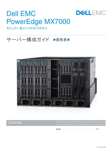
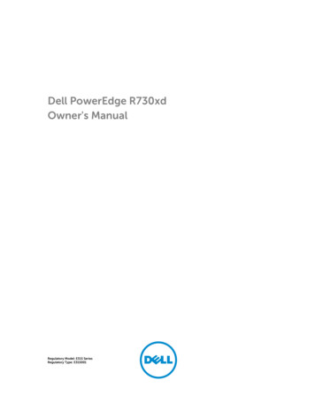
2Hardware overviewThis section briefly describes the hardware that is associated with this solution, including the models that areused to validate the deployment example in this document. Appendix A contains a complete listing ofhardware and software that is validated for this guide.2.1Dell EMC PowerEdge MX7000Figure 1 shows the front view of the PowerEdge MX7000 chassis. The left side of the chassis has one ofthree control panel options: LED status light panelTouch screen LCD panelTouch screen LCD panel equipped with Dell EMC PowerEdge iDRAC Quick Sync 2The bottom of Figure 1 shows six hot-pluggable, redundant, 3,000-watt power supplies. Above the powersupplies, eight compute and storage sleds are available. In the example below, the sleds contain: (MX7000HW configuration shown for information only, not representative of deployment example) Four Dell EMC PowerEdge MX740c sleds in slots one through fourOne Dell EMC PowerEdge MX840C sled in slots five and six (not used in examples)Two Dell EMC PowerEdge MX5016s sleds in slots seven and eightDell EMC PowerEdge MX7000 – front6Dell EMC Networking – PowerEdge MX7000 vSAN Ready Node Deployment Guide
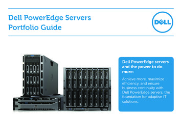
2.1.1Dell EMC PowerEdge MX7000 (back)The MX7000 includes three I/O fabrics. Fabric A and B for Ethernet and future I/O module connectivity, andFabric C for SAS and Fibre Channel (FC) connectivity. Each fabric provides two slots to provide redundancy.Figure 2 shows the back of the PowerEdge MX7000 chassis. From top to bottom, the chassis is configuredwith: (MX7000 HW configuration shown for information only, not representative of deployment example) One Dell EMC Networking MX9116n Fabric Switching Engine (FSE) installed in fabric slot A1 (notused in examples)One Dell EMC Networking MX7116n Fabric Expander Module (FEM) installed in fabric slot A2(not used in examples)Two Dell EMC Networking MX5108n Ethernet switches installed in fabric slots B1 and B2Two Dell EMC Networking MXG610s Fibre Channel switches installed in fabric slots C1 and C2(not used in examples)Two Dell EMC PowerEdge MX9002m modules that are installed in management slots MM1 andMM2Dell EMC PowerEdge MX7000 – back2.2Dell EMC Networking MX9116n Fabric Switching EngineThe Dell EMC Networking MX9116n Fabric Switching Engine (FSE) is a scalable, high-performance, lowlatency 25 Gbps Ethernet switch purpose-built for the PowerEdge MX platform. The MX9116n FSE providesenhanced capabilities and cost-effectiveness for the enterprise, mid-market, Tier 2 cloud, and NFV serviceproviders with demanding compute and storage traffic environments.In addition to 16 internal 25 GbE ports, the MX9116n FSE provides: 7Two 100 GbE QSFP28 portsTwo 100 GbE QSFP28 unified portsTwelve 200 GbE QSFP28-Double Density (DD) portsDell EMC Networking – PowerEdge MX7000 vSAN Ready Node Deployment Guide
The QSFP28 ports can be used for Ethernet connectivity, and the unified ports support SAN connectivitysupporting both NPIV Proxy Gateway (NPG) and direct attach FC capabilities.The QSFP28-DD ports provide capacity for more uplinks, VLTi links, connections to rack servers at 10 GbE or25 GbE using breakout cables. Also, the QSFP28-DD ports provide fabric expansion connections for up tonine extra MX7000 chassis using the MX7116n Fabric Expander Module. An MX7000 chassis supports up tofour MX9116n FSEs in Fabric A and/or B.Dell EMC Networking MX9116n FSEThe following MX9116n FSE components are labeled in Figure 3:1.2.3.4.5.6.7.8.Express service tagStorage USB portMicro-B USB console portPower and indicator LEDsHandle releaseTwo QSFP28 portsTwo QSFP28 unified ports12 QSFP28-DD portsNote: The MX9116n is not used in the validation of the deployment examples. However, the MX9116n can besubstituted for the MX5108n to take advantage of its enhanced capabilities and port options.2.3Dell EMC Networking MX5108n Ethernet switchThe Dell EMC Networking MX5108n Ethernet switch is targeted at small PowerEdge MX7000 deployments ofone or two chassis. While not a scalable switch, it still provides high-performance and low latency with anonblocking switching architecture. The MX5108n provides line-rate 25 Gbps Layer 2 and Layer 3 forwardingcapacity to all connected servers with no oversubscription.Besides the eight internal 25 GbE ports, the MX5108n provides: One 40 GbE QSFP portTwo 100 GbE QSFP28 portsFour 10 GbE RJ45 BASE-T portsThe ports can be used to provide a combination of network uplink, VLT interconnect (VLTi), or for FCoEconnectivity. The MX5108n supports FCoE FIP Snooping Bridge (FSB) mode but does not support NPG or8Dell EMC Networking – PowerEdge MX7000 vSAN Ready Node Deployment Guide
direct attach FC capabilities. An MX7000 chassis supports up to four MX5108n Ethernet switches in Fabric Aand/or B.Dell EMC Networking MX5108n Ethernet switchThe following MX5108n components are labeled in Figure 4:1.2.3.4.5.6.7.8.2.4Express service tagStorage USB portMicro-B USB console portPower and indicator LEDsModule insertion/removal latchOne QSFP portTwo QSFP28 portsFour 10GBASE-T portsDell EMC PowerEdge MX5000s SAS moduleThe Dell EMC PowerEdge MX5000s SAS module supports a x4 SAS internal connections to all eightPowerEdge MX7000 front-facing slots. The MX5000s uses T10 SAS zoning to provide multiple SASzones/domains for the compute sleds. Storage management is conducted through the OEM-M console.The MX5000s provides Fabric C SAS connectivity to each compute and one or more MX5016s storage sleds.Compute sleds connect to the MX5000s using either SAS host bus adapters (HBA) or a PERC RAIDcontroller in the mini-mezzanine PCIe slot.The MX5000s switches are deployed as redundant pairs to offer multiple SAS paths to the individual SASdisk drives. An MX7000 chassis supports redundant MX5000s in Fabric C.Dell EMC PowerEdge MX5000s SAS moduleThe following MX5000s components are labeled in Figure 5:9Dell EMC Networking – PowerEdge MX7000 vSAN Ready Node Deployment Guide
1.2.3.4.2.5Express service tagModule insertion/removal latchPower and indicator LEDsSix SAS portsDell EMC PowerEdge MX9002m moduleThe Dell EMC MX9002m module controls overall chassis power, cooling, and hosts the OpenManageEnterprise - Modular Edition (OME-M) console. Two external Ethernet ports are provided to allowmanagement connectivity and to connect additional MX7000 chassis in a single logical chassis. An MX7000supports two MX9002m modules for redundancy. Figure 6 shows a single MX9002m module and itscomponents.Dell EMC PowerEdge MX9002m moduleThe following MX9002m module components are labeled in Figure 6:1.2.3.4.5.6.2.6Handle releaseGigabit Ethernet port 1Gigabit Ethernet port 2ID button and health status LEDPower status LEDMicro-B USB portDell EMC PowerEdge MX740c (vSAN Ready Node)The PowerEdge MX740c is a two-socket, full-height, single-width compute sled offering impressiveperformance and scalability. It is ideal for dense virtualization environments and can serve as a foundation forcollaborative workloads. An MX7000 chassis supports up to eight MX740c sleds.PowerEdge MX740c key features include: 10Single-width slot designTwo CPU sockets24 DIMM slots of DDR4 memoryDell EMC Networking – PowerEdge MX7000 vSAN Ready Node Deployment Guide
Boot options include BOSS-S1 or IDSDMUp to six SAS/SATA SSD/HDD and NVMe PCIe SSDsTwo PCIe mezzanine card slots for connecting to network Fabric A and BOne PCIe mini-mezzanine card slot for connecting to storage Fabric CiDRAC9 with Lifecycle ControllerDell EMC PowerEdge MX740c sled with six 2.5-inch SAS drives2.7Dell EMC PowerEdge MX5016s storage SledThe PowerEdge MX5016s sled delivers scale-out, shared storage within the PowerEdge MX architecture. TheMX5016s provides customizable 12 Gb/s direct-attached SAS storage with up to 16 HDDs/SSDs. Both theMX740c and the MX840c sleds can share drives with the MX5016s using the dedicated PowerEdge MX5000sSAS module. Internal server drives may be combined with up to seven MX5016s sleds in one chassis forextensive scalability. An MX7000 chassis supports up to seven MX5016s storage sleds.11Dell EMC Networking – PowerEdge MX7000 vSAN Ready Node Deployment Guide
Dell EMC PowerEdge MX5016s sled with the drive bay extended12Dell EMC Networking – PowerEdge MX7000 vSAN Ready Node Deployment Guide
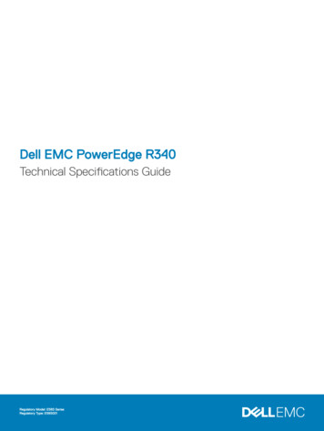
3Topology overviewThis section provides information about the two solutions that are used in this document. Both topologies usea single chassis to deploy vSAN Ready Nodes. The first topology is suited for small scale deployments wheremost of the networking, storage, and compute is located within the chassis. The second topology is suited forlarger scale deployments where the chassis is part of a data center network with more racks of storage andcompute resources.3.1Data Center-in-a-box (Example 1)The first deployment example is a stand-alone chassis that is commonly found in small businesses andremote office/branch office (ROBO) environments. The networking solutions are likely to be small, Layer 2deployments, with most of the storage and compute resources within the chassis.Data Center-in-a-box - external network interface connectionsThe following list summarizes the key networking characteristics of this example: A Single pair of MX5108n switches-13VLT configuration provides switch redundancy2-port NIC to each server provides link redundancy25 GbE switch ports to 25 GbE server NICDell EMC Networking – PowerEdge MX7000 vSAN Ready Node Deployment Guide
vSAN considerations- 100 GbE switch uplink port per switch to an external networkvSAN, management, vMotion, and all compute traffic on the same linkStorage-MX5016s Storage Sled provides up to 16 extra SAS drivesMX5000s SAS module enables the use of storage sled and external SAS storage (notshown)Figure 10 shows the connections of a single server internal to the MX7000 chassis. This diagram is to help inunderstanding the types of traffic present on the links from the server to the MX switches. The combination ofMX switch configuration and virtual networking settings within vSphere controls the traffic types.A logical representation of a server to switch networking for Data Center-in-a-box example3.2Chassis in leaf-spine (Example 2)The second deployment example is a stand-alone chassis that is found in medium to large data centerenvironments. This topology is suited for customers that want to deploy a stand-alone chassis into anestablished network such as a leaf-spine network commonly found in large data centers. This solution can bemodified to deploy into a Layer 2 or Layer 3 leaf-spine.14Dell EMC Networking – PowerEdge MX7000 vSAN Ready Node Deployment Guide
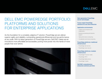
Chassis in leaf-spine – external network connectionsThe following list summarizes the key networking characteristics of this example: Two pairs of MX5108n switches- VLT configuration provides switch redundancyTwo 2-port NICs on each server provides link redundancy to each switch25 GbE switch ports to 25 GbE server NICs100 GbE switch uplink port per switch to an external networkThe second switch is used to segregate and provide dedicated links for vSAN storage trafficvSAN considerations-vSAN storage traffic on dedicated links and switchManagement, vMotion, and all compute traffic on a separate link and switchThe following logical diagram shows the connections of a single server internal to the MX7000 chassis. Thisdiagram is to help in understanding the types of traffic present on the links from the server to the MXswitches. The combination of MX switch configuration and virtual networking settings within vSphere controlsthe traffic types.15Dell EMC Networking – PowerEdge MX7000 vSAN Ready Node Deployment Guide
A logical representation of server to switch networking for Chassis in leaf-spine example16Dell EMC Networking – PowerEdge MX7000 vSAN Ready Node Deployment Guide
4Example 1 – Data Center-in-a-boxThis section provides step-by-step instruction on configuration of networking related settings to deploy avSAN within the MX7000 chassis. Topology diagrams and information about this example are in Section 3.14.1Chassis setup requirementsThis section provides initial conditions of the chassis, servers, and storage sled before beginning networkconfiguration. The installation and setup of the chassis and servers are not within the scope of this document.Initial MX7000 chassis and server conditions: MX7000 chassis installed and powered on (includes two MX9002m modules)MX740c vSAN Ready Node servers (4qty) installed in chassisMX5016s storage sled installed in chassisMX5108n switches installed in fabric A1 and A2MX5000s Storage I/O modules installed in fabric C1 and C2MX7000 chassis management access configured (IP addresses assigned to chassismanagement)MX5016s HDD/SSD disks are assigned to appropriate serversBest practice- Update all associated firmware and softwareNote: This document does not provide steps to configure management access to the MX7000 chassis.Access to the switch command line can be accomplished through the MX9002m on a management network,or through the USB serial port on the front panel of the switch. Instructions on setting MX9002m and MXswitch management IP addresses can be found in the Dell EMC OpenManage Enterprise-Modular EditionVersion 1.00.01 for PowerEdge MX Chassis User's Guide or Dell EMC PowerEdge MX Ethernet NetworkingDeployment Guide.4.2vSAN networking recommendationsThis section lists the networking recommendations that are used in vSAN clusters. These recommendationscan be found in the VMware Validated Design for Software-Defined Data Center (SDDC) documentation atVMware Validated Design Documentation. These recommendations are listed here for reference only.The following recommendations do not encompass the entire set of design decisions for the SDDC: 17CSDDC-PHY-NET-003: Use two ToR switches for each rack to provide redundancyCSDDC-PHY-NET-004: Use VLANs to segment physical network functionsCSDDC-PHY-NET-008: Configure the MTU size to at least 9000 bytes (jumbo frames) on thephysical switch ports and distributed switch port groups that support vSAN and vMotion trafficCSDDC-VI-NET-001: Use vSphere Distributed Switch (vDS)CSDDC-VI-NET-003: Use the route that is based on the physical NIC load teaming algorithm forall port groups except for ones that carry VXLAN traffic. VTEP kernel ports and VXLAN traffic useroute based on SRC-IDCSDDC-VI-Storage-SDS-001: Use only 10 GbE or higher for vSAN trafficCSDDC-VI-Storage-SDS-003: Configure jumbo frames on the VLAN dedicated to vSAN trafficDell EMC Networking – PowerEdge MX7000 vSAN Ready Node Deployment Guide
4.3CSDDC-VI-Storage-SDS-004: Use a dedicated VLAN for vSAN traffic for each vSAN enabledclusterAdministering VMware vSAN (VMware vSAN 6.7) recommends the using the teaming algorithmRoute based on physical network adapter load, the recommended failover configuration isActive/ActiveSwitch configurationThis section provides steps to configure Dell EMC Networking MX5108n switches running Dell Networkingoperating system 10.4.0E (R3S). The process requires basic familiarity with OS10 configuration and networkswitches.4.3.1Check switch operating system versionUse the following command to verify that the operating system version on the switch is 10.4.0E (R3S) or later:If not, go to www.force10networks.com or www.dell.com/support/software to download the latest operatingsystem version for the switch.OS10# show versionDell EMC Networking OS10 EnterpriseCopyright (c) 1999-2018 by Dell Inc. All Rights Reserved.OS Version: 10.4.0E.R3SBuild Version: 10.4.0E.R3S.268Build Time: 2018-07-12T00:29:26-0700System Type: MX5108N-ONArchitecture: x86 64Up Time: 2 days 00:43:494.3.2Factory default configuration (optional)Enter the following commands to set the switch to factory defaults:OS10# delete startup-configurationProceed to delete startup-configuration [confirm yes/no(default)]:yesOS10# reloadSystem configuration has been modified. Save? [yes/no]:noContinuing without saving system configurationProceed to reboot the system? [confirm yes/no]: yesThe switch reboots with factory default settings and is ready to configure using the default username andpassword of admin/admin.4.3.3Switch management settings (GUI)Ensure that the MX chassis and switches are powered on and operational, and management access hasbeen established.To configure the IOM-A1 switch, use the OpenManage Enterprise Modular GUI and select the IO ModularSlot A1 device. The following figure shows the IOM-A1 network settings page on the OpenManage EnterpriseModular GUI:18Dell EMC Networking – PowerEdge MX7000 vSAN Ready Node Deployment Guide
Note: The default configuration for switch management is DHCP. Figure 13 shows an example of aconfiguration using static IP address settings.IOM-A1 management network settings4.3.4Switch configuration (CLI)MX switches operate in one of two modes, Full Switch or SmartFabric. Ensure that the switch is operating inFull Switch mode for these examples. For additional information about switch modes, see Dell EMCPowerEdge MX Network Architecture Guide.OS10# show switch-operating-modeSwitch-Operating-Mode: Full Switch ModeTable 2 contains example VLAN and IP address information. Use the addresses in Table 2 throughout theswitch configuration steps.Table 2 VLAN and IP addresses used in example configurationsPurposeVLANIOM-A1IOM-A2VRRP (gateway)OOB switch managementNA100.67.164.171100.67.164.172NAESXi management
1 Introduction The new Dell EMC PowerEdge MX, a unified, high-performance data center infrastructure, provides the agility, resiliency, and efficiency to optimize a wide variety of traditional and new, emerging data center