Transcription
MARTIN DC3700/DC2500 GARAGE DOOR OPENER SYSTEMDC3700: Belt only up to 12’ (3700) high doors / DC2500: Chain only up to 10’ (3050) high doors .renepOrooDtseteiuQs’dlroWTheINSTRUCTION MANUALFor Installation of residential garage doors:-All brands* - Center mount only-Martin models WL, RA, HT, FL SL, SP CM, MO, CH - Center or side mount-Martin Electric (combination) models WLE, HTE, CME, RAE, FLE, CHE - Center or side mountSee page 5 forIMPORTANT INSTALLATION, MAINTENANCE & SAFETY INSTRUCTIONSThis instruction manual features “Low Risk” Martin Finger Shield Garage DoorsWARNING! The back page helps you determine if your garage door is *“HIGH RISK”.TMRMSTISO 9001FINA8949R E GIMARTIDOOR OPENERSCEREDULRUSF.C.C.CertifiedMARTIN DOOR MFG.Martin Door Manufacturing Salt Lake City, Utah 84127-0437 USAwww.martindoor.com Printed in the USA 20m Copyright 20022/2002AD-IM09-05
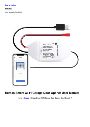
“C”BRACKETSOPTIONALPUNCHED ANGLEMARTIN SIDE MOUNT OPENER INSTALLATION- May be mounted right side or left side WARNING! For Martin Finger Shield Garage Door Systems only.POWERHEADCHASSISRAIL SUPPORT BRACKETRAIL ASSEMBLYEND STOP WITH CLEVISPIN AND COTTER RINGANTENNAWIREBELT OR CHAINPOWERHEADOPENER HEADER BRACKETLIGHTLENSTORSION TUBETROLLEYSTRUTTORSION SPRINGEND STOP WITH CLEVISPIN AND COTTER RINGOPENERHEADERBRACKETEMERGENCYRELEASECORDOPENER DOOR BRACKETEMERGENCYRELEASETAGTOP DOOR SECTIONSTRAIGHT AND CURVEDPOWER ARMKNOBWARNING AND SAFETY LABEL3/8” X 1” SHORT NECKCARRIAGE BOLT AND3/8” LOCK NUTWALLCONTROLORPUSHBUTTONPACKET FOR OWNERSDOOR AND OPENERINSTRUCTION MANUALSOPENER DOOR BRACKET3/8” X 1” SHORT NECKCARRIAGE BOLT AND2- 3/8” LOCK NUTSTOP ROLLER BRACKETPHOTOEYETOP DOOR SECTION2COPYRIGHT 2002 MARTIN DOOR
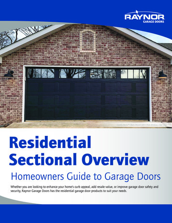
MARTIN CENTER MOUNT OPENER INSTALLATION- May be mounted off center OPTIONAL“C”PUNCHED ANGLEBRACKETSPOWERHEADCHASSISRAIL SUPPORT BRACKETRAIL ASSEMBLYANTENNAWIREPOWERHEADEND STOP WITH CLEVISPIN AND COTTER RINGBELT OR CHAINLIGHTLENSOPENER HEADER BRACKETTROLLEYTOP STRUTTORSION TUBEEMERGENCYRELEASECORDTORSION SPRINGOPENER DOOR BRACKETEMERGENCYRELEASETAGTOP DOOR SECTIONSTRAIGHT AND CURVEDPOWER ARMKNOBWARNING AND SAFETY LABELWALLCONTROLORPUSHBUTTONPACKET FOR OWNERSDOOR AND OPENERINSTRUCTION MANUALSPHOTOEYEPHOTOEYECOPYRIGHT 2002 MARTIN DOOR3
!TO REDUCE THE RISK OF SEVERE INJURY ORDEATH, READ AND FOLLOW ALL INSTRUCTIONSDo not install this opener or any other opener on "HIGH RISK" garage doors that may cause severe injury, entrapment or death!See back page for serious injuries which may occur if “HIGH RISK” areas are left uncorrected.Martin Finger Shield Garage Doors are “Low Risk”.IMPORTANTINSTALLATION INSTRUCTIONSIMPORTANTMAINTENANCE & SAFETY INSTRUCTIONSUntrained or Negligent Installing, Adjusting and Servicing can be Dangerous! Thegarage door springs and related parts can cause serious injury or death! IF YOU AREUNSURE, CALL A TRAINED MARTIN DOOR DEALER!Monthly, check the opener's down cycle safety reverse. The door must reverse when itcontacts a 1 1/2" (38) high object (or a 2X4 board laid flat) on the floor, in line with the dooropener. A closing door must also reverse if the photo eyes are interrupted. See Steps 12,13.Garage door should be balanced and easy to open and close by hand.Always keep the moving door in sight and away from people and objects until it iscompletely closed. NO ONE SHOULD CROSS THE PATH OF THE MOVING DOOR.Locks should be disabled and pull down ropes should be removed.Locate wall control/push button within sight of door, at min. height of 5' (1520) sosmall children cannot reach it, and away from all moving parts of door. See Step 8.Emergency release tag should be installed above knob and adjusted to about6' (1830) above the floor. Opener should be 7’ (2130) above floor. See Step 9.Risk of electrical shock is explained in Step10. Do not connect opener to sourceof power until instructed to do so.Entrapment and warning labels should be installed next to the wall control/pushbutton as explained in Step 14.Do not allow children to operate or play with the garage door controls. Keep the remotecontrol away from children.The emergency release should only be used when garage door is in the closed position.Weak or broken springs may cause door to fall if released in the open position, increasingthe risk of severe injury or death. Use caution when using the release with door open.Monthly visually check the lift cables, spring assembly, hardware, etc. for wear and stability.If the Safety Reverse or any other part of the garage door and opener system do not workproperly, or if you do not understand, call a trained Martin Door Dealer.SAVE THESE IMPORTANT INSTRUCTIONSTHE FOLLOWING ITEMS ARE HELPFUL TO COMPLETE A SATISFACTORY MARTIN GARAGE DOOR OPENER INSTALLATION:HammerALL MEASUREMENTS INLevel (magnetic)PARENTHESIS ( ) AREHacksawMILLIMETERS IN THISWire CuttersINSTRUCTION MANUAL.18’ (5.5) measuring tapeSocket wrench set for 7/16“ (11), and 9/16” (14) with 3“ (76) extensionRegular and phillips screwdriverEnd wrench set for 7/16“ (11), and 9/16” (14)10/40 motor oil lubricantWax lubricant (paraffin, candle, etc.)Cordless drill with 1/8“ (3), 13/64” (5), 1/4” (6) bitsplus 1/4” and 3/8” (6 and 10) masonry bits12. Step ladder (not shown)13. Pencil14. Punched angle opener hanger: 8' X 1-1/4" X 1-1/4" (2440 X 32 X 32)NOTE: Bolts, lock nuts and lag screws for fastening the punched angle arefurnished with the door opener hardware fasteners.COPYRIGHT 2002 MARTIN DOOR2.1.13.3.WAX 0MOTOROIL5.DO ORS6.6.NTM8.7.14.11.5
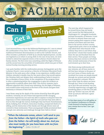
OPENER DOOR BRACKET GUIDELINESLEFT SIDE MOUNT INSTALLATIONOPENER DOOR BRACKETONLY Martin Finger Shield Garage Door Systems allow youto choose center, off center or side mounting for a safer,more attractive opener installationOPENER POWER ARM MUST BE FASTENEDOUTSIDE THE OPENER DOOR BRACKETWARNING! Other brand doors are designed for center mounted3/8”x1”SHORTNECKCARRIAGEBOLTopeners only. Off center or side mounted installations may resultin other brand doors binding, side shifting, twisting, and falling, asthe lift cables detach from the cable drums.SPECIAL GUIDELINES:OPENER DOOR BRACKETSTRUT (IF PROVIDED)3/8” LOCK NUTSFor 8" (203) low clearance track installations, the strut andthe opener door bracket are fastened 2" (51) lower thanshown.TOP ROLLERBRACKETCURVEDPOWER ARMFor 2 ½" (64) and 4 ¼" (108) low clearance trackinstallations the opener door bracket and top roller bracket arelowered 2" (51). The strut is not lowered. Fasten the openerpower arm to the top hole of the opener door bracket.ENDSTILEA Martin Opener requires 1 ½" (38) more clearance than therequired garage door clearance.Doors over 18'2" (5540) wide should use side mount openerinstallation only. The opener door bracket will not fit on widedoors with “U” / “C” struts and double end stiles. If door hasdouble end stiles with double top roller brackets, drill out holein end of curved power arm to 7/16" (14) and attach direct tothe long stem roller shaft between the double top rollerbrackets. This makes a solid side mount opener installation.CENTER AND OFF CENTER MOUNT INSTALLATIONOPENER POWER ARM SHOULD BE FASTENEDINSIDE THE OPENER DOOR BRACKET3/8”x1” SHORT NECKCARRIAGE BOLTOPENER DOOR BRACKETTORSION TUBECURVEDPOWER ARMOPTIONAL POWER ARM ANGLEREQUIRED STRUTOILCURVEDPOWERARMBOLTFASTEN OPENER POWERARM DIRECTLY TO HOLEAT SAME HEIGHT ASTOP ROLLERSBOLTHEADOPENERPOWERARMFASTEN TWONUTS TIGHTAGAINSTPOWER ARMANGLESTILEFULL HEIGHTPOWER ARMANGLE3/8” LOCK NUTSPOWER ARMANGLE(FASTEN POWER ARM ANGLE TO STILE WITH 5 1/4” X 1” THREAD FORMING SCREWS AS SHOWN.)6DRILL 1/8” (3) HOLE AND FASTEN OPENERCOPYRIGHT 2002 MARTIN DOORDOOR BRACKET TO STRUT AND DOOR SECTION
INSTALLATION INSTRUCTIONS FOR A MARTIN DC3700 GARAGE DOOROPENER SYSTEMFIGURE 1THIN VERTICAL MARKHEADERTHESE INSTRUCTIONS ARE INTENDED FOR PROFESSIONAL GARAGE DOOROPENER INSTALLERS. READ THROUGH THE COMPLETE INSTRUCTION MANUAL ANDAPPLICABLE SUPPLEMENTAL INSTRUCTIONS BEFORE BEGINNING.STEP 1FASTENING THE OPENER DOOR BRACKETStudy "Opener Door Bracket Guidelines” on page 6.CENTER MOUNTDecide if the opener will be mounted to the center, off center or side of the garage door.Center and off center mounted openers always require a “full width” top strut on the door. Ifside mounted, Martin Doors up to 12'2" (3700) wide may or may not require a top strut.Fasten the opener door bracket under the top roller bracket for side mounting or on thestile and strut for center/off center mounting. Fasten with 1/4” x 1” Thread Forming Screws.CURVED POWER ARMREQUIRED“FULL WIDTH”TOP STRUTTEMPORARY TIEFasten the curved power arm to the opener door bracket with 3/8" X 1" short neck carriagebolt and two 3/8" lock nuts as shown in the “Opener Door Bracket Guidelines” on page 6.Raise the curved opener power arm straight up and touch the torsion tube or spring. Makea vertical mark on header, in line with the power arm. This mark will be the verticallycentered location for the opener header bracket. See Figure 1Note: To hold the top of the curved power arm from falling down, temporarily tie it to the topof the door bracket or strut. See Figure 13/8” X 1” SHORT NECKCARRIAGE BOLT AND2- 3/8” LOCK NUTSFIGURE 2THIN VERTICAL MARKOPENER HEADERBRACKETHEADERTHINHORIZONTALMARKSTEP 2FASTENING THE OPENER HEADER BRACKETMake a horizontal mark on the header 2" (51) above the highest movement of the door asit opens. See figure 2.The following are approximate measurements above the top of a closed door to thehorizontal mark on the header:OPENER DOORBRACKET1/4” X 1” THREADFORMING SCREWS11 ½” (292)Regular Clearance5/16” X 2” LAG SCREWSCENTER MOUNT11 1/2" (292) for 12” (305) regular clearance track.CURVED POWER ARM6 1/2" (165) for 8" (203) low clearance track.5" (127) for 4 1/4" (108) low clearance track.3 1/2" (89) for 2 ½" (64) low clearance track.Fasten the opener header bracket to the header with two 5/16" X 2" lag screws. Thevertical and horizontal marks are the “centered location” marks.COPYRIGHT 2002 MARTIN DOORREQUIRED“FULL WIDTH”TOP STRUTTEMPORARY TIETOP OFCLOSED DOOR1/4” X 1” THREADFORMING SCREWSOPENER DOORBRACKET7
STEP 3FASTENING THE RAIL ASSEMBLY TO THE POWER HEADPlace the rail assembly onto the power head chassis by lining up the sprocket assemblyopening with motor shaft. Make sure the shaft engages teeth inside sprocket assembly.Press rail assembly down firmly onto shaft and power head chassis. DO NOT HAMMER!FIGURE 36 X 14 mmCHASSIS SCREWFasten 2 "C" brackets over rail assembly and onto chassis. Flanges on "C" brackets mustfit into the four recessed areas on chassis. The rail assembly must be at a right angle tothe power head for the "C" brackets to fit properly. See Figure 3SPROCKETOPENING“C” BRACKETRAIL ASSEMBLYInsert 6 X 14 mm chassis screws through "C" bracket holes and into chassis holes, andtighten screws by hand with a phillips screw driver. The “C” brackets must firmly hold railassembly to chassis. See Figures 3, 4.POWER HEAD CHASSISDo not remove tape around the trolley and straight power arm until Step 9. The trolleyhas been taped at the correct location so that the belt or chain position tab will activate theposition switch, and opener computer correctly. The activation begins when the openeropens the door, from the closed position, for the first time. See Figure 5POSITION SWITCHSTEP 4FASTENING THE RAIL ASSEMBLY TO THE OPENER HEADER BRACKETPlace power head on stepladder, positioning front of rail assembly on torsion tube (or ontorsion spring if side mounted) for stability. See Figure 5FIGURE 4MOTORSHAFT“C” BRACKETSPOWER HEAD CHASSIS6 X 14 MM CHASSISSCREWPosition rail assembly end-stop within the opener header bracket and insert clevis pinthrough the end-stop and opener header bracket Attach thecotter ring to the end of the clevis pin. See Figure 6OPENER HEADER BRACKET“TAPE AROUND TROLLEY”(DO NOT REMOVE UNTILSTEP 9)FIGURE 5SPROCKETASSEMBLYOPENINGTORSION SPRINGTIETORSION TUBEPOWER HEADCURVED POWER ARMRAIL ASSEMBLYFIGURE 6 (Top View)TOP DOOR SECTIONOPENER HEADER BRACKET“C” BRACKETEND STOPCLEVIS PINPOWER HEADTOP DOORSECTIONYBLMLADDERRA8COTTER RINGESSAILCOPYRIGHT 2002 MARTIN DOOR
FIGURE 9FIGURE 73/8” X 1” SHORT NECKCARRIAGE BOLTSRAILASSEMBLYILTSTEP 5MOUNT OPENER TO CEILINGRaise the opener power head high enough to allow the door tobe fully opened. OPEN DOOR BY HAND. Set a 1 ½" (38) highobject on the top part of the door, under the rail assembly. Centerthe rail assembly with the opener door bracket. See Figure 11T WISTwist rail support bracket onto rail assembly. See Figures 7and 85” (127)PUNCHEDANGLERALEBLYBSI MVI EIN ASSRAILSUPPORTBRACKETSlide the rail support bracket forward or backward on the railassembly to the best location for fastening to the ceiling. SeeFigure 8FIGURE 8RAIL ASSEMBLYFasten the 5” (127) punched angle and the rail supportbracket locks to the rail support bracket. See Figure 9Fasten optional punched angle diagonally from 5” (127)punched angle to ceiling for correct stability. See Figure 11POWER HEADRAILSUPPORTBRACKETNOTE: If clearance is limited, the rail support bracket can befastened directly to the ceiling with no 5” (127)punched angle or rail support bracket locks.See Figure 8RAIL SUPPORTBRACKETLIRAE LYLB BSI MVI EIN ASSFIGURE 10RAIL SUPPORTBRACKET LOCK3/8” LOCK NUTSRAIL ASSEMBLY5” (127)PUNCHEDANGLEFasten an extra rail support bracket to 13'6" (4100) or 15'6" (4700) long rail assemblies forextra high doors. Fasten the extra rail support bracket to the rail assembly at about 30% to50% back from header. See Figure 12RAIL SUPPORTBRACKETFIGURE 115/16” X 2” LAG SCREWRAIL SUPPORTBRACKET LOCK“C” BRACKETPOWER HEADCHASSISOPTIONAL PUNCHED ANGLE1 1/2” (38) HIGHOBJECTFIGURE 12RAIL SUPPORT BRACKETRAIL ASSEMBLYOPTIONALPUNCHED ANGLEPOWER HEADRAIL SUPPORT BRACKETTOP DOOR SECTIONSTRUTRAIL ASSEMBLYPOWER HEADCURVED POWER ARMCOPYRIGHT 2002 MARTIN DOOREXTRA RAIL SUPPORTBRACKET FOR 13’6” (4100)OR 15’6” (4700) RAILASSEMBLYTEMPORARY TIE9
STEP 6LIGHT BULBS AND LIGHT LENSESTwist 2 light bulbs (1 for DC2500), maximum 60W, into light bulb sockets.Position light lens tabs with corresponding slots in power head chassis. Snap light lensonto chassis first. Next, position light lens tabs with slots in power head and snap securelyinto place. See Figure 12A or 12BSTEP 7PHOTO EYES SAFETY SYSTEMCLOSE DOOR BY HAND BEFORE BEGINNING!MOUNTING PHOTO EYES DIRECTLY TO SIDE WALL:Locate mounting position 3" (76) to 5" (127) above the floor. Mark and drill 1/16" (1.5) pilothole into wall. (If mounting to concrete or drywall instead of wood, use anchors providedand drill 3/16" (5) pilot hole).FIGURE 12ATABLYIL ONRA LYTBLBE SEMASLIGHT BULBLIGHT BULBSOCKETLIGHT BULBSLOTSPOWER HEADCHASSISLIGHT LENSPOWERHEADDC3700TABSLOTSLIGHT LENSFIGURE 12BFasten tapered-head screw into wall. Do not tighten screw. Allow screw head to protrude(approximately 3/8" (9.5)) from wall.Position the top slot hole on the back of the photo eye holder onto screw and push downto lock in place. See Figure 13CHAIN RAILASSEMBLY ONLYLIGHTLENSLIGHT BULBFasten tapered head screw through the curved channel slot at the bottom of the photoeye holder after drilling correct pilot hole. Repeat process for other photo eye and photoeye holder. See Figure 13POWER HEADDC2500ANTENNA WIREFIGURE 13Align photo eyes so they face each other. In Step 12 you will be instructed to check thealignment. Tighten wing nut on each photo eye by hand. See Figure 14MOUNTING PHOTO EYES TO BRACKET:Locate mounting position 3" (76) to 5" (127) above the floor for photo eye brackets.Brackets can be mounted in any position as long as photo eye beam has a clear path fromone side of door to the other side after mounting. See pages 4 and 5Mark and drill two 1/16" (1.5) pilot holes into wall. (If mounting to concrete or drywallinstead of wood, use anchors provided and drill two 3/16" (5) pilot holes).Using round-head screws provided, fasten bracket to wall. Attach photo eye to bracket byaligning tabs and center pin and snapping into place Photo eye wiring should exitdownward. Repeat process for other bracket. See Figures 15 and 16TOPSLOTHOLE10WING NUTWINGNUTBOLTPHOTO EYEPHOTO EYEHOLDERSCURVEDCHANNELSLOTTAPEREDHEAD SCREWDOWN WARD EXITFOR WIRINGTAPERED HEADSCREWFIGURE 15WINGNUT BOLTFIGURE 16ROUNDHEAD SCREWPHOTO EYEWITH HOLDERAlign photo eyes so they face each other. In Step 12 you will be instructed to check thealignment. Tighten wing nut on each photo eye by hand. See Figure 16ATTENTION: In dual door installations, the "Receiver" photo eyes (as marked on each ofthe photo eyes) should be mounted on the far outsides. The "Transmitter"photo eyes should be mounted on the insides.FIGURE 14TAPERED HEADSCREWPHOTO EYEBRACKETSCENTERPINPHOTOEYEWITHHOLDERROUNDHEAD SCREWWINGNUTBOLTWING NUTWIRING EXITS DOWNCOPYRIGHT 2002 MARTIN DOOR
***STEP 7 CONTINUED***CONNECTING WIRES TO POWER HEADRoute wiring through clip on bottom of photo eye holder, then run wires along wall and ceiling to power headchassis. Use provided staples to fasten wiring to wall, joists and/or ceiling. Do not pinch wiring.FIGURE 17RAIL ASSEMBLYPHOTO EYEWIRINGNOTE: As an alternative, the wiring can be routed along the top of the rail assembly, or along the outside of thegarage door track. Be sure the wiring is routed away from all moving parts of door and rail assembly.Open the control panel cover by slightly pulling on the cutout, allowing the cover to hang open. To remove, pull firmlyon the cover corner near one of the hinges. Do not twist cover or hinges may break. See Figure 23WIREGUIDETERMINALAREARoute wires through wire guide at top of power head chassis into terminal area of control panel. Separate the dbl.wire from each photo eye into two single wires: 1) the white wire and 2) the black striped wire. See Figure 17Remove about 1/2" (13) of insulation from the end of each of the four single wires. Twist the whitewire ends together and twist the black striped wire ends together. Insert twisted white wire endsfirmly into terminal hole #1 by pushing directly into hole. If wires are difficult to insert, a screwdrivermay be used to depress the terminal tab while inserting the wires. To remove wiring, depress terminaltab again and pull wiring out. Repeat procedure for the twisted black striped wire ends, except insertthem into terminal hole #2. See Figure 17STEP 8WALL CONTROL / PUSH BUTTONThe wall control/push button will allow you to control your garage door from inside the garage. Itmust be mounted within sight of the garage door, clear of all moving garage door parts or anyassociated parts, at least 5’ (1520) above the floor, out of children's reach. The wall control/pushbutton should only be used when the door area is free of people or any obstructions.CONTROL PANELFIGURE 17 - CLOSE-UPWIREGUIDEPOWER HEADCHASSISTERMINAL TABSTERMINALHOLESFASTENING THE WALL CONTROL:Attach wiring to back of wall control. White wire end attaches to terminal #3 screw, black striped wire endattaches to terminal #4 screw.POWER HEADLocate where top mounting screw will go. Mark location on wall. Drill 1/16" (1.5) pilot hole into wall.Fasten top screw into wall with screw head out from wall about 1/8” (3). Fasten wall control into topslot hole by pushing down firmly onto screw head. For drywall, concrete, etc., drill 3/16” (5) pilot hole foranchors. See Figure 18TERMINALNUMBERSFIGURE 18Mark and drill 1/16"(1.5) pilot hole through bottom screw hole. Insert screw through bottom hole from the front,and tighten screw. Route wiring from behind through one of the recessed cutouts. Avoid pinching the wires.CONNECTING WIRES:Route wiring through cutout, along wall and ceiling, to opener power head chassis. Use provided staples to securewiring. Do not pinch wiring.WALL RERoute wiring through wire guide of chassis to terminal area of control panel. See Figure 17SCREWSTRUTRemove about 1/2" (13) of insulation from the end of each wire. Insert white wire end firmly into terminal hole #3.Insert black striped wire end into terminal #4. To remove wiring, depress tab and pull out wiring. Multiple wallcontrols may be installed, parallel or series, if wires are properly connected to terminals 3 and 4 as explained.COPYRIGHT 2002 MARTIN DOORBLACKSTRIPEDWIREBOTTOMSCREWHOLE11
STEP 9FASTENING POWER ARMSClose the garage door by hand.FIGURE 19REMOVE TAPERAIL ASSEMBLYRemove tape from rail assembly holding straight powerarm and allow it to hang freely. See Figure 19TROLLEYPull the emergency release cord to disconnect trolley.Slide trolley to about 12" (305) from the opener headerbracket. See Figure 20STRAIGHTPOWERARMPosition straight power arm and curved power arm so atleast two sets of holes line up.Pull the emergency release cord to activate trolley. Opendoor manually until trolley locks with belt or chainconnector inside rail assembly. Pulling down on theemergency release cord with the attached knob connectsor disconnects the trolley to the connector on the chain orbelt. See Figure 21Always close the door before releasing the trolley from theconnector. The emergency release tag must be installedabove the knob and adjusted to about 6' (1830) above thefloor. See Figure 20Do Not Use the Emergency Release Cord And Knob ToPull Door Open Or Closed.FIGURE 21CURVEDPOWERARMEMERGENCY RELEASE CORDTEMPORARY TIEOPENERDOORBRACKETEMERGENCYRELEASETAGKNOBFIGURE 2012 ”MIN (305)IMUMFasten arms together with 3/8" X 1" short neck carriagebolts and 3/8" lock nuts. Remove Temporary Tie.See Figures 19 and 20TORSION TUBERAIL ASSEMBLYTROLLEY3/8” LOCK NUTRAIL ASSEMBLYSTRAIGHT AND CURVEDPOWER ARMEMERGENCY RELEASE CORD3/8” X 1” SHORT NECK CARRIAGE BOLTEMERGENCY RELEASE CORDPULL DOWNOPENERDOORBRACKETPULL DOWN TO ENGAGEPULL DOWN TO DISENGAGEKNOB12KNOBCOPYRIGHT 2002 MARTIN DOOR
FIGURE 22STEP 10CONNECT OPENER TO POWERCORD AND PLUGTo reduce the risk of electric shock, your opener is provided with an insulatedpower cord with a 3-prong grounding plug. The power cord permits easyconnection to and disconnection from an electrical outlet. The power cord must beplugged-in to a standard grounded outlet. If there is no outlet available at thelocation, you must have a qualified electrician install an approved-grounded outletat the proper location.OPTIONAL PERMANENT WIRINGSTRAIN G! To help prevent electrocution or fire, etc., the installation and wiring andoutlet must be done in accordance with local electrical and building codes. DO NOTuse an extension cord. DO NOT use a 3-prong to 2-prong plug adapter. DO NOTmodify or cut off the grounding pin on the plug.PERMANENTWIRINGPlug the power cord into a properly grounded outlet. The#8 LED on the openercontrol panel will illuminate, showing that the power is on. See Figure 23CONDUITOPTIONAL PERMANENT WIRING: (If required by your local electrical code)WARNING! Contact a qualified electrician to run the necessary wiring to youropener and to perform the electrical connections.GROUND (GREEN)HOT (BLACK)NEUTRAL (WHITE)TERMINAL BLOCKLIGHT SOCKETDisconnect the power at the circuit breaker.Remove the Power Head Housing. Unsnap the power cord strain relief cover bydisengaging the tabs. Cut the power cord within 6" (152) of the terminal block.Replace the strain relief cover by snapping tabs back into place. Knock out conduithole, and bring in the permanent wiring and conduit. Secure conduit to chassis.Attach wiring using suitable wire nuts (not provided). Reinstall power head housing.FIGURE 23POWER CORDGROUNDED OUTLETCONTROL PANEL BUTTONSCONTROL PANEL COVERConnect power at the breaker. The #8 LED on the opener control panel willilluminate, showing that the power is on. See Figure 22STEP 11MARTIN “SMART COMPUTER” CONTROL PANELLED’SPOWERHEADCONTROLPANELCOVERREMOVEDOpen and remove the control panel cover by pulling firmly on the cover cornernear one of the hinges. Do not twist cover or hinges may break. See Figure 23The 3 Control Panel Buttons are labeled "P", " ", and "-”. The circular displaycontains 8 numbered LED’s. See Figure 24FIGURE 24MARTIN “SMART COMPUTER” CONTROL PANELNOTE: When setting the adjustments, face the garage door while looking up at thecontrol panel.STRUTThe LED’s show useful information regarding the opener’s normal use as well asTroubleshooting. See Figure 24CIRCULAR LED DISPLAYCOPYRIGHT 2002 MARTIN DOORCONTROL PANEL BUTTONS13
***STEP 11 CONTINUED***SETTING THE ADJUSTMENTSBefore beginning, confirm that the garage door is closed, the opener installation iscomplete, the trolley is connected to the chain or belt connector, and the #8 LED isilluminated showing that the power is on.FIGURE 25The adjustments that can be made are Open Travel Limit, Close Travel Limit, OpeningForce, Closing Force, and the first Transmitter Programming.BEGIN PROGRAMMINGREFER TO THE FOLLOWING TO PROGRAM OR CHANGE THE PROGRAM OF THEMARTIN “SMART COMPUTER”:FIGURE 26TO PROGRAMPress and hold the "P" button for about 5 seconds. When all LEDs illuminate release thebutton. See Figure 25OPEN TRAVEL LIMITLED #2 should be blinking. Press and hold the " " until the door is in the openedposition. Release this button. If the door is not in the desired position, press the " " buttonor the "-" button to move it slightly. Once the door is in the desired position, press andrelease the "P" button. See Figure 26OPEN TRAVEL LIMITFIGURE 27CLOSE TRAVEL LIMITLED #4 should be blinking. Press and hold the "-” button until the door is in the closedposition. Release the button. If the door is not in desired position, press the " " or the "-"button to move it slightly. Once the door is in the desired position, press and release the"P" button. See Figure 27Attention! Do not close door tight on floor.CLOSE TRAVEL LIMITFIGURE 28UP FORCELED #2 and #6 should be blinking. Press and release the " " or "-" button once. Theilluminated LEDs around the display will display the current force setting. By pressing the" " or "-" key, the force can be increased ( ) or decreased (-). The force should be set aslow as possible. A suggestion is LEDs #1 and #2 should illuminate for one-car size doorsand LEDs #1, #2, #3 for two-car size doors. Once the desired force is selected, press andrelease the "P" button. See Figure 28UP FORCE14COPYRIGHT 2002 MARTIN DOOR
***STEP 11 CONTINUED***DOWN FORCELED #4 and #6 should be blinking. Press and release the " " or "-" button once. Theilluminated LEDs around the display will display the current force setting. By pressing the" " or "-” key, the force can be increased ( ) or decreased (-). The force should be set aslow as possible. A suggestion is LEDs #1 and #2 should illuminate for one-car size doorsand LEDs #1, #2, #3 for two-car size doors. Once the desired force is selected, press andrelease the "P" button. See Figure 29TRANSMITTER PROGRAMMINGLED #7 should be blinking. While LED #7 is blinking, press and hold the desired button onthe transmitter. When the LED #7 blinks rapidly, release the transmitter button. Theopener has now learned the particular code of this transmitter. Press and release the "P"button. This stores the code in memory. See Figure 30END PROGRAMMINGLED #8 should be illuminated. Press transmitter button to open and close the door twotimes. This allows the opener smart computer to set its complete memory and "learn" theproper operating levels. Each time the door is opened or closed the #5 LED illuminatesabout 2 seconds as the belt or chain activates the position switch on the power headchassis. This is a visual check regarding computer memory retention. The “smartcomputer” retains memory even after a power outage. See Figure 31NOTE: If one setting needs to be changed without adjusting any of the other settings,simply press and hold the "P" button for about 5 seconds, then press and release"P" repeatedly until the desired setting is reached. This bypasses the unneededadjustments. When desired setting is complete, simply press "P" as many times asneeded to return the opener to normal operating mode with LED #8 illuminated.!FIGURE 29DOWN FORCEFIGURE 30TRANSMITTER PROGRAMMINGFIGURE 31END PROGRAMMINGTO REDUCE THE RISK OF SEVERE INJURY ORDEATH, READ AND FOLLOW ALL INSTRUCTIONSIMPORTANT MAINTENANCE & SAFETY INSTRUCTIONSMonthly, check the opener's down cycle safety reverse. The door must reverse when itcontacts a 1 1/2" (38) high object (or a 2X4 board laid flat) on the floor, in line with the dooropener. A closing door must also reverse if the photo eyes are interrupted. See Steps 12,13.The emergency release should only be used when garage door is in the closed position.Weak or broken springs may cause door to fall, if released in the open position, increasingthe risk of severe injury or death. Use caution when using the release with door open.Always keep the moving door in sight and away from people and objects until it iscompletely closed. NO ONE SHOULD CROSS THE PATH OF THE MOVING DOOR.Monthly visually check lift cables, spring assembly, hardware, etc. for wear and stability.Do not allow children to operate or play with the garage door controls. Keep the remotecontrol away from children.If the Safety Reverse or any other part of the garage door and opener system do not workproperly, or if you do not understand, call a trained Martin Door Dealer.COPYRIGHT 2002 MARTIN DOORKEEP GARAGE DOOR PROPERLY BALANCED. See garage door owner’s manual. Animproperly balanced door increases the risk of severe injury or death. Call a trained MartinDoor Dealer to repair lift cables, spring assemblies and other hardware.SAVE THESE IMPORTANT INSTRUCTIONS15
STEP 12TEST DOWN FORCE REVERSALPlace a 1 1/2”(38) high object (or a 2X4 laid flat) on the floor, inline with the door opener. When the closing door contacts theobject, it should stop, reverse, and automatically return to theopen position. If the door does not reverse, reset the down travellimit so that the door travels slightly further down in the closeddirection. Then, retest the unit as described above. See Figure 32FIGURE 32WALL CON
MARTIN DC3700/DC2500 GARAGE DOOR OPENER SYSTEM TM DOOR OPENERS MARTIN DC3700: Belt only up to 12' (3700) high doors / DC2500: Chain only up to 10' (3050) high doors . INSTRUCTION MANUAL.! IMPORTANT . on the floor, in line with the door opener. A closing door must also reverse if the photo eyes are interrupted. See Steps 12,13. Always .