Transcription
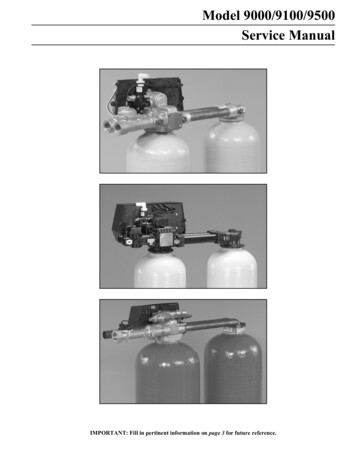
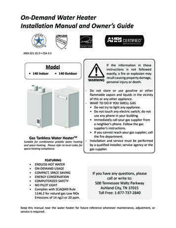
Heating loadsCooling loadsWater flow1.Calculations:i. Continuing the AB line to the saturation line to get the detailsof Point C (the ADP): The ADPtc 7·5 C db g c 0·0064 kg/kg dahc 23·66 kj/kg daAir flowAcousticsSometimes these definitions may be written in terms of wet-bulbtemperatures, but the scale of wet-bulb temperatures is not linear onthe psychrometric chart so there will be errors.This may be deemed acceptable if the margin of error is small. Mostpractical coil selections have typical contact factors of between 0·.8and 0·.9, but this should be checked with the manufacturer beforecarrying out the final calculation.2. The above equations for QS and QL are key to understanding theenergy transfers involved in moving round the psychrometric chart.The following section contains sevenbuilding services engineering topic areasrelated to the design of water flowdistribution systems.WATER FLOW DISTRIBUTIONSYSTEMSThe following two pages contain flowcharts of the relevant design andcalculation processes.The first flow chart shows the seventopics within this section.The second flow chart provides anoverview of the process, showing someof the many related topics that need tobe considered in the design of water flowdistribution systems. The boxeshighlighted in blue show an area that isfully or partially covered within one of theseven topic areas in this section, or inthe rest of the guidance, with theappropriate reference numbers given. BSRIA BG 30/2007 – LICENSED TO UNIVERSITY OF HONG KONG LIBRARY GUIDE TO HVAC BUILDING SERVICES CALCULATIONS81
Heating loadsCooling loadsWater flowAir flowAcousticsFLOW CHART 1 – TOPICS WITHIN THIS SECTION82LIBRARYGUIDE TO HVAC BUILDING SERVICES CALCULATIONS BSRIA BG 30/2007 – LICENSED TO UNIVERSITY OF HONG KONG
Heating loadsCooling loadsWater flowAir flowAcousticsFLOW CHART 2 – OVERVIEW OF SYSTEM DESIGN PROCESS BSRIA BG 30/2007 – LICENSED TO UNIVERSITY OF HONG KONG LIBRARY GUIDE TO HVAC BUILDING SERVICES CALCULATIONS83
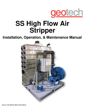
Heating loadsCooling loadsWater flowAir flowAcousticsW1 PIPE SIZING - GENERAL84LIBRARYGUIDE TO HVAC BUILDING SERVICES CALCULATIONS BSRIA BG 30/2007 – LICENSED TO UNIVERSITY OF HONG KONG
Heating loadsCooling loadsWater flowOverviewThis section makes numerous references to CIBSE Guide C. The2001 edition (and previous editions) provided a range of pressureloss data tables based on the Colebrook-White equation. The 2007edition of the guide makes use of the Haaland equation and thepressure-loss tables are removed from the guide and replaced byan accompanying spreadsheet (supplied on CD). The spreadsheetcan be used to calculate pressure loss based on the Haalandequation. The spreadsheet can also be used to generate pressureloss data tables in the style of the previous editions of CIBSEGuide C.Whenever a fluid flows along a pipe, there will be a loss ofpressure due to friction. This pressure drop depends, among otherfactors, on the fluid velocity. So, for a required fluid flow rate, thepipe diameter and pressure loss are related. A small diameter pipewill result in high fluid velocity and so a high pressure loss; alarger pipe carrying the same flow rate will result in a lowervelocity and pressure loss. Pipe sizing involves determining themost appropriate pipe diameters to use and the resulting velocitiesand pressure losses.There are limits to acceptable fluid velocity. High velocities leadto noise and erosion while low velocity can give problems withair-locking (CIBSE Guide C, Table 4.6). While pipe capital costsare obviously related to diameter, the running costs for pumpedsystems, are proportional to pressure loss. Therefore, pipe sizinginvolves value engineering.With gravity systems, (for example cold water down services), theavailable head is the limiting factor. Pipe sizing involvesdetermining the pipe sizes which will deliver the design flow rateat a total pressure loss equal to this head.Pressure loss is found to be proportional to velocity pressure:1DP µ ρv22For practical purposes, the pressure losses through straight pipesand pipe fittings are dealt with separately.Straight pipesThe equation above is written as:DP λl 1 2x ρvd 2(Known as the D’Arcy Equation)Where:DP r λ l v d pressure loss (Pa)density of the fluid (kg/m 3 )friction factorlength of pipe (m)mean velocity of water flow (m/s)internal pipe diameter (m)Air flowAcousticsValues of λ are calculated using the Haaland equation:é 6 9 æ k / d ö1 11 ù -1 8 log ê ç úλêë R e è 3 71 ø úû1Where:λ Re k d friction factorReynolds numberequivalent roughnessinternal pipe diameter (m)The Haaland equation is used as the basis for the pressure losscalculation procedure in the CIBSE Guide C spreadseheet.(See sheet W2 Pipe sizing – straight lengths for a workedexample.)(See Design Watchpoint 1.)Pipe fittingsIn this case the above equation is written as:DP ζ x1 2ρv2Where z is the coefficient of velocity pressure loss. Values of z arefound from tables in Section 4 of CIBSE Guide C.(See sheet W3 Pipe sizing – fittings for a worked example.)Pipe sizesStandard pipe sizes quoted are nominal and are not the internaldiameter. In CIBSE Guide C internal diameters are listed in tables4.2, 4.3 or 4.4.Fluids other than waterSee CIBSE Guide C Section 4.6 and 4.7 for guidance concerningthe flow of steam and natural gas in pipes.Design information requiredType of system suppliedFor example radiators and cooling coils and batteries. This willdetermine what is acceptable in terms of flow temperatures,pressure drops and noise. Consult a senior engineer as necessary.Details of fluidFor example water, gas and glycol solution.This will enable fluid properties to be determined such as fluiddensity and viscosity.Ø Design tip: If the system fluid is chilled water containing glycol,then the specific heat capacity will need to be adjusted.Fluid temperatureFor example whether hot or chilled water. Typical flowtemperatures for low temperature hot water systems are 70-95 oC,and for primary chilled water are 6-12 oC.Design flow and return temperaturesTo give the temperature drop across system. This will be needed todetermine the required mass flow rate. BSRIA BG 30/2007 – LICENSED TO UNIVERSITY OF HONG KONG LIBRARY GUIDE TO HVAC BUILDING SERVICES CALCULATIONS85
Heating loadsCooling loadsWater flowAir flowAcousticsW1 PIPE SIZING – GENERALØ Design tip: Do not assume that 82/71 C must be used for lowtemperature hot water systems. Doubling the temperature dropwill have a relatively small effect on the heating surface requiredbut will reduce the flow rate required by half, therefore the pipesizes and the pump duty will be smaller. The control of the heatoutput will also be improved.Pipe materialFor example copper, steel etc. This determines pipe roughness andhence the flow characteristics and pipe pressure losses.Pipe insulation detailsWhether pipes are insulated and, if so, insulation details – thisgoverns losses from the pipes and the extra heating or coolingrequired to compensate for this.Pipe system layoutWater flow temperatures – chilled waterChilled water primary circuits flow temperatures: 6-12 oCChilled water secondary circuits flow temperatures: 10-15 oCWater velocitiesSteel pipe up to 50 mm diameter: 0 75-1 5 m/sSteel pipe over 50 mm diameter: 1 25-3 m/sSmall bore systems: 1 m/sMicrobore systems: 1 2 m/sCorrosive water systems: 2m/s maximum.Pressure dropTypical range for re-circulating system pipe sizes over 50 mm is100-300 Pa/m. For under 50 mm a similar range may be used but itis essential to check that the velocity is acceptable. CIBSE Guide C,suggests a suitable starting point of 250 Pa/m.Including pipe lengths, number and type of fittings etc.Distribution space availableHorizontally and vertically such as false ceiling depths and risers.Further information is available in CIBSE Guide C, section 4 andCIBSE Guide B1, Section 5.1.3 and appendix A1.3/ Guide B,Section 1.5.1.3 and appendix 1.A1.3.Details of ambient conditionsSurrounding air temperature and whether the pipes will have to runthrough chilled or outdoor spaces.Key design inputs· Design mass flow rates in kg/s· Limiting maximum pipe pressure loss per metre run in Pa/m· Limiting maximum and minimum flow velocity in metres persecondØ Design tip: A minimum velocity may also be set to avoid scalesettling etc.Design outputs· Schematic of pipework layout and associated plant showingrequired flow rates· Schedule of pipe sizes and lengths, and fittings such as elbowsand valvesDesign approachPipe sizing should ensure that both pressure drop and velocity areacceptable to ensure efficient operation. Pipe diameter is thereforeoften selected on a pre-determined pressure drop per unit length ora pre-determined velocity. The design criteria may require asystem that is designed with a pre-selected pressure drop but alsooperates within a maximum velocity limit. Note the following:ReferencesCIBSE Guide B1, Heating, Section 5.1.3 and appendix A1.3,2002, ISBN 1 9032 8720 0CIBSE Guide B, Section 1.5.1.3 and appendix 1.A1.3, 1005, ISBN1 90328720 58 8CIBSE Guide C, Reference Data, Section 1, 2007,ISBN 978 1903287 80 4BSRIA, Rules of Thumb, BG 14/2003, BSRIA 2003,ISBN 0 86022 626 3Lawrence Race G, Pennycook K, Design Checks for HVAC – AQuality Control Framework for Building Services Engineers –sheets 28 and 46, BG 4/2007, BSRIA 2007, ISBN 978 086022 6697See also:Sheet W2 Pipe sizing - Straight lengthsSheet W3 Pipe sizing - Pressure drop across fittingsSheet W4 System resistance for pipework - Index runDESIGN WATCHPOINTS1.Design should minimise pipe and valve noise, erosion, installationand operating costs.Small pipe sizes can result in high flow velocities, noise, erosion,and high pumping costs.Large pipe sizes will increase installation costs and make it difficultto vent air.Rule of thumb design dataWater flow temperature – heating2.3.4.oLTHW: 70-95 CMTHW: 100-120 oCHTHW: over 120 oC(Above 95 oC the system should be pressurised to avoid the risk offlash steam formation.)5.If pipe materials or flow temperatures differ markedly from thestandard tables then pipe sizing should be done using initialfluid flow equations with appropriate data. Otherwise errorscould occur, resulting in incorrectly sized pumps andinadequate heat delivery.Check that both flow velocities and pressure drops are withinacceptable limits.Check pipes and fittings can withstand maximum systemworking pressure.Check that all of the system operates under positive staticpressure to ensure any leaks are obvious and air does notenter system.Pipework systems can suffer from a number of problems thatmust be considered during design – including:····86LIBRARYGUIDE TO HVAC BUILDING SERVICES CALCULATIONSdirt blockagesair lockingerosion - due to cavitation effect and the scouring effectof dirt particlescorrosion - if system materials and water quality are notcarefully considered. BSRIA BG 30/2007 – LICENSED TO UNIVERSITY OF HONG KONG
Heating loadsCooling loadsWater flowAir flowAcousticsW2 PIPE SIZING – STRAIGHT LENGTHSOverviewIn order to size pipework both straight lengths and fittings need tobe considered. Initial pipe sizing is done by considering straightruns alone, but for complete system design and pump sizing bothstraight runs and fittings need to be considered.The examples in the pipe sizing, index run and pump sizing sheets(W2-5) are shown as manual calculations. Although calculationsare often done on a spreadsheet or by using a computer sizingpackage, these will still require input and design decisions thatrequire familiarity with the fundamental theory and manual sizingprocedures.Step 5. Size pipe using the CIBSE Guide C pipe sizingspreadsheet. Select an appropriate pipesize using the mass flowrate and the selected value of either pressure drop per metre run orvelocity.Ø Design tip: Pipe sizing and pressure loss data for a system canbe laid out in a tabular format and converted to a spreadsheet.ExampleFind the pipe size for a 10 m straight run of medium steel heatingpipe carrying water at 75 C and serving four fan convectors, eachrated at 4 15 kW output.Design information requiredPipe length in metresThis may already have been provided on schematics.(See also sheet W1.)(See Design Watchpoint 1.)Fluid type and operating temperatureThe specific heat capacity, density and viscosity of fluids willdepend on the type used. (Properties of various fluids are given inCIBSE Guide C Appendix 4.A1.)Temperature drop across system (K) t across the system.Pipe materialCalculation procedure (manual pipe sizing)Step 1. If not already laid out, sketch the system underconsideration, indicating pipe lengths and unit loads (kW).Allocate a reference number to each length of pipework.Step 2. Estimate the heat loss for each section (often taken as apercentage of unit load such as 5-10%, or as a typical value suchas 25 W/m run for insulated heating pipes, 100 W/m run for uninsulated pipes) to give the total load for each section. The heatloss will depend on pipe orientation (vertical/horizontal) and thequality and installation of insulation. Heat losses can be less than5% if the pipes are well insulated.Ø Design tip: Typical values can be obtained by estimating thepipe size and reviewing heat loss data in tables 3.19 - 3.26 ofCIBSE Guide C.Ø Design tip: Part L of the Building Regulations coversConservation of Fuel and Powers. Maximum permissible heatlosses for hot water, heating and cooling pipes can be obtainedfrom the Non-Domestic Heating, Cooling and VentilationCompliance Guide.Step 1. A simple sketch above shows the necessary informationStep 2. Estimate the heat loss with an assumed estimated loss as6% of the load.Hence:Total fan coil load 4 x 4 15 16 6 kW,6% of 16 6 0 996 kWTotal load 17 6 kWStep 3. Temperature drop across system assumed as 10K, fromQ m& Cp DtWhere:Q load (kW)Cp specific heat capacity of water (kJ/kg.K)Dt temperature difference (K)Mass flow rate is therefore:17 6m& 0 42 kg/ s4 2 10Step 4. A nominal pressure drop per metre run of 250 Pa/m isselectedStep 3. Select an appropriate temperature drop across the system,such as 10-20 K for low pressure hot water and, assuming this tobe constant across the system, calculate the mass flow rate in eachsection.Step 5. Using the CIBSE Guide C pipe sizing spreadsheet formedium grade steel pipe with winter at 75 C, size the pipe to givethe required mass flow rate and pressure drop per metre run.Using the individual results section of the spreadsheet it can befound that a 25 mm diameter pipe will give a velocity of 0·73 m/swith a pressure loss of 241 Pa/m. Alternatively the spreadsheetcan be used to produce a pressure-loss data table.Step 4. Select an acceptable design value for either pressure dropper unit length or velocity. (See sheet W1 and seek advice fromsenior engineer as required.)Note that a worked example demonstrating the calculationprocedure used by the CIBSE pipesizing spreadsheet is providedin Section 4.A2.1 of CIBSE Guide C.Cross-check: a velocity of 0 73 m/s is acceptable for 25 mm steelpipe BSRIA BG 30/2007 – LICENSED TO UNIVERSITY OF HONG KONG LIBRARY GUIDE TO HVAC BUILDING SERVICES CALCULATIONS87
Heating loadsCooling loadsWater flowAir flowAcousticsW2 PIPE SIZING – STRAIGHT LENGTHSNote that as an alternative approach to step 2, an experiencedestimate of pipe size of 25 mm gives a heat loss for uninsulatedsteel pipe of 92 W/m run ( CIBSE Guide C, table 3.19), in otherwords 920 W. This is 5 55 % of the total load, therefore theoriginal assumed loss of 6% is reasonable.Ø Design tip: Review the impact of a change of temperature dropacross the system. Larger temperature drops (20K is common inEurope) can reduce pipe sizes considerably, but this will requiremore careful balancing of the system when commissioning.Ø Design tip: For occupied spaces consider omitting heat lossesfrom radiator sizes. Any heat loss from the pipes to the occupiedspace is useful heating. As long as the total design capacity isavailable, it does not matter that some comes from the pipes andsome from the emitters. This will also reduce pipe size, andreduce unnecessary system over sizingReferencesCIBSE Guide B1, Heating, Section 5.1.3, and appendix A1.3, 2002,ISBN 19032 8720 0/CIBSE Guide B, Section 1.5.1.3, appendix1.A1.3, 2005, ISBN 1 9032 8720CIBSE Guide C, Reference Data, Section 1, 2007,ISBN 978 1903287 80 4BSRIA, Rules of Thumb, BG 14/2003, BSRIA 2003, ISBN 0 86022626 3Lawrence Race G, Pennycook K, Design Checks for HVAC – AQuality Control Framework for Building Services Engineers –sheets 26 and 46, BG 4/2007, BSRIA 2007, ISBN 978 086022 6697Department for Communities and Local Government, NonDomestic Heating, Cooling and Ventilation Compliance GuideSee also:Sheet W1 Pipe sizing - GeneralSheet W3 Pipe sizing - Pressure drop across fittingsSheet W4 System resistance for pipework - Index runDESIGN WATCHPOINTS1.2.88LIBRARYIf taking dimensions from drawings use dimensions shownrather than scaling off, as drawings can become distorted ifphotocopied.If pressure drop was selected, check that the velocity falls withina reasonable range and vice versa.GUIDE TO HVAC BUILDING SERVICES CALCULATIONS BSRIA BG 30/2007 – LICENSED TO UNIVERSITY OF HONG KONG
Heating loadsCooling loadsWater flowAir flowAcousticsW3 PIPE SIZING – PRESSURE DROP ACROSS FITTINGSOverviewThere are two methods of calculating the total pressure lossthrough a fitting:DP 5 Pv z 0 5 r v 2 CIBSE Guide C, equation 4 11)Where:DP z r v Pv total pressure loss (Pa),pressure loss factordensity (kg/m 3 )velocity (m/s)0·5x p v2 velocity pressureCalculation procedureTo calculate the pressure loss through a fitting the following stepsare required:Step 1. Find the appropriate velocity pressure loss factor ( z)value for the fitting in tables 4.20-4.39 of CIBSE Guide C.Step 2. Determine the velocity pressure in the pipe using theGuide C pipe sizing spreadsheet.Step 3. Calculate DP using CIBSE Guide C equation 4.11.Note that velocity pressures (P v ) are also available in CIBSEGuide C Table 4.10.Values of DP/1 can be determined using the CIBSE Guide C pipesizing spreadsheet. The spreadsheet also calculates the velocitypressure (Pv).ExampleCalculate the pressure loss through a 90 sharp elbow with asmooth radiused inner of 25 mm diameter connected to a mediumgrade steel pipe and passing a water flow rate of 0 5 kg/s at 75 C.The z values represent the fraction of one velocity pressure thathas the same pressure loss as the fitting.Step 1. From CIBSE Guide C table C4.21 (pressure loss factorsfor elbows) the z value for a 90 sharp elbow with a smoothradiused inner with a 25 mm diameter is 0 8.Design information required(See also sheet W1 pipe sizing – general)Step 2. From the CIBSE Guide Cspreadsheet a velocity pressure of369 Pa is obtained.Pipe system layoutStep 3. The pressure lossassociated with the elbow can becalculated fromPipe lengths, location, number and type of fittings,Pipe sizesWhen the straight length diameters have been calculated, thecorresponding l e and DP/l for each section may be required. Whencalculating the pressure drop across a branch fitting, the z for thestraight section and branch section will be determined separatelyThese will then be used to calculate the pressure drop across bothparts of the branch.Mass flow rateThe mass flow rate through each section and therefore through thefittings is required. Again, with a fitting such as a swept divergingtee, (such as a branch), the mass flow-rate at each part of the teewill be required. For example, one flow into the tee (1) and twoflows out of the tee (2 and 3) as shown below:DP z Pv 0·8 369 295PaReferencesCIBSE Guide B1, Heating, Section 5.1.3, and appendix A1.3,2002, ISBN 19032 8720 0/ Guide B, Section 1.5.1.3 and appendixA1.3, 2005, ISBN 1 903287 58 8CIBSE Guide C, Reference Data, Section 1, 2007,ISBN 978 1903287 80 4BSRIA, Rules of Thumb, BG 14/2003, BSRIA 2003,ISBN 0 86022 626 3Lawrence Race G, Pennycook K, Design Checks for HVAC – AQuality Control Framework for Building Services Engineers –sheets 28 and 46, BG 4/2007, BSRIA 2007, ISBN 978 086022 6697See also:Sheet W1 Pipe sizing - GeneralSheet W2 Pipe sizing - Straight lengthsSheet W4 System resistance for pipework - Index runDESIGN WATCHPOINTS1.A common mistake is to apply the z for a tee piece to the wrongpart of the branch. The values of z in CIBSE Guide C should beused with the velocity pressure (P v ) of the combined flow. BSRIA BG 30/2007 – LICENSED TO UNIVERSITY OF HONG KONG LIBRARY GUIDE TO HVAC BUILDING SERVICES CALCULATIONS89
Heating loadsCooling loadsWater flowAir flowAcousticsW4 SYSTEM RESISTANCE FOR PIPEWORK – INDEX RUNOverviewThe index run within a system is the circuit that has the highestresistance to the flow of water and supplies the index heat emitter.This is the worst case possible when considering pressure losseswithin a system. It is usually, but not always, the longest circuit inthe system. Sometimes a shorter run with a greater number offittings or items of equipment can be the index run.The index pd (pressure drop) is required in order to successfullysize the pump for the system. If the pump can work to the pressuredemands of the index run then all other circuits will work.To identify the index run, the pressure drop for several circuitsmay need to be found. The pressure drop across each length ofpipe, fitting and terminal within these circuits will need to becalculated to determine the total pressure drop for each circuit. Theone with the largest pressure drop will be the index.Ø Design tip: Balancing a system is necessary to achieve thecorrect pressure losses and flow rates through the differentcomponents of a system. If the layout of the system issymmetrical, then the amount of commissioning required tobalance the system is reduced. This is true for both water andair systems.Design information requiredSee also sheet W1 Pipe sizing – general.Step 2. Add up the total direct pressure losses from each sectionwithin a circuit to give a circuit pressure drop.Step 3. Identify the index run by examining each circuit pressuredrop to identify the highest pressure drop.ExampleIdentify the index run and calculate the index run pressure drop forthe following two-pipe system serving two panel radiators, eachrated at 4 15 kW. The water temperature is 75 C.Design dataHeat EmittersFor two heat emitters at 4 15 kW each, a 6% emission loss frompipework has been added when calculating the mass flow rate.Assume a Dt of 10K across the system.Cp 4 2kJ/ kgKQ (2 4 15) 1 06 8 8kwFrom:Q mcp& Dtm& 8 8 0 21kg/ s4 2 10Number of circuitsFrom the CIBSE Guide C pipe sizing spreadsheet, a 20 mm pipewith a flow of 0 2 kg/s gives a DP/l of 212 Pa/m and a velocitypressure (Pv ) of 165 Pa.Each circuit within a multi-circuit system needs to be clearlyidentified.Step 1. Identify the different sections and their design details.Pipe sizing detailsAll pipework and fittings should have been sized with pressuredrop per unit length ( DP/l) velocity pressure (P v) and pressure lossfactor (z). Data is available from tables such as those found insection 4 of CIBSE Guide C and the pie sizing spreadsheet.Ø Design tip: Often the longest circuit is the index run but there isalways the possibility of a shorter circuit with many fittings beingthe index run.Calculation procedureStep 1. Identify each section and where it begins and ends. Forexample, section 1 starts at the combined flow side of the teefitting in the return, goes through the boiler and ends at thecombined flow side of the tee fitting in the flow. Assign areference to each section. Identify each fitting within each sectionand determine the design details: pressure drop per unit length(D/Pl) velocity pressure (P v) and pressure loss factor (z).Section 1: GreenSection 2: RedSection 3: BlueStep 4. Identify each circuit by the sections it consists of, forexample: circuit A 1,2,3, circuit B 2,3,4 and so on.Section detailsSection 1Step 5. Calculate all direct pressure losses across fittings andpipe work in each sectionFor fittings use:DP z PvFor straight pipe use:DP (DP/l) l90LIBRARYGUIDE TO HVAC BUILDING SERVICES CALCULATIONSStraight Pipe work: length 25 m, m& 0 21 kg/s, diameter 20mm.Elbow: Smooth radiused inner diameter: 20 mm, z value: 0 75(Table 4.21 CIBSE Guide C.)Boiler: Sectional boiler z value: 1 5. BSRIA BG 30/2007 – LICENSED TO UNIVERSITY OF HONG KONG
Heating loadsCooling loadsWater flowAir flowAcousticsW4 SYSTEM RESISTANCE FOR PIPEWORK – INDEX RUNSection 2Straight pipe work: length 8 m, m& 0 105 kg/s, diameter 15mm, DP / l 251Pa/ m,Pv 133Pa.Radiator: panel radiator z value: 2 5.Diverging tee with reduction: z value 1 30 (Table 4.33 CIBSEGuide C).Converging tee with enlargement: z value 2 98, (Table 4.34CIBSE Guide C).Section 3Straight pipework: length 13 m, m& 0 105 kg/s, diameter 15 mm, DP / l 251Pa/ m,Pv 133Pa.Elbow (two off): Smooth radiused inner diameter 15mm, z value 0 93 (Table 4.21 CIBSE Guide C).Radiator: panel radiator z value 2 5.Diverging tee with reduction: z value 0 57, (Table 4.33 CIBSEGuide C).Converging tee with enlargement: z value 1 63, (Table 4.34CIBSE Guide C).Values of z for radiators and boilers are found in table 9.1 ofHeating & Air Conditioning of Buildings Faber & Kell, NinthEdition. (See Design Watchpoint 1.)Step 2. Now identify the circuits in the system;Circuit A consists of section 1 and 2,Circuit B consists of section 1 and 3.Step 3. Calculate the pressure loss across each fitting and thepipework for each section. (See Design Watchpoint 2.)There are two branches in this example. For both, the combinedflow forms part of section 1; therefore as the velocity pressure (P v)to be used is that of the combined flow, the value for this exampleis 165 Pa.Section 1: GreenSection 2: RedSection 3: BlueSection 2Straight pipe: 8 m 251 Pa/m 2008 PaRadiator: 2 5 133 Pa 333 PaDiverging tee: 1 3 165 Pa 215 PaConverging tee: 2 98 165 Pa 492 PaTotal 3048 PaSection 3Straight pipe: 13 m 251 Pa/m 3263 PaElbow (2 off): 2 0 93 133 Pa 247 PaRadiator: 2 5 133 Pa 333 PaDiverging tee: 0 57 165 Pa 94 PaConverging tee: 1 63 165 Pa 269 PaTotal 4206 PaStep 4. Add up total section losses for each circuit.Circuit A Total pressure loss 5672 Pa 3048 Pa 8720 Pa, (8 7 kPa)Circuit B Total pressure loss 5672 Pa 4206 Pa 9879 Pa, (9 9 kPa)Step 5. The index circuit in this example is Circuit B.Ø Design tip: Often, as in this case, the index circuit is obvious byinspection. But, if in doubt, check all circuits. Otherwise there isa risk of undersizing the pump and poor system performance.ReferencesCIBSE Guide A, Environmental Design, 2006,ISBN 1 903287 669CIBSE Guide B1, Heating, Section 5.1.3, and appendix A1.3,2002, ISBN 19032 8720 0/Guide B, Section 1.5.1.3 and appendixA1.3, 2005, ISBN 1 903287 58 8CIBSE Guide C, Reference Data, Section 1, 2007,ISBN 978 1903287 80 4BSRIA, Rules of Thumb, BG 14/2003, BSRIA 2003,ISBN 0 86022 626 3Lawrence Race G, Pennycook K, Design Checks for HVAC – AQuality Control Framework for Building Services Engineers –sheets 28 and 46, BG 4/2007, BSRIA 2007, ISBN 978 086022 6697Heating & Air Conditioning of Buildings , Ninth Edition, Faber &Kell. ISBN 075 064 642 XSee also:Sheet W1 Pipe sizing - GeneralSheet W2 Pipe sizing - Straight lengthsSheet W3 Pipe sizing - Pressure drop across fittingsSheet W5 Pump sizing.Pressure loss for each sectionSection 1Straight pipe: 25 m 212 Pa/m 5300 PaElbow: 0 75 165 Pa 124 PaBoiler: 1 5 165 Pa 248 PaTotal 5672 PaDESIGN WATCHPOINTS1.2.This example has the same heat emitters in both circuits. Thismay not always be the case.When calculating the pressure loss through a fitting such as thebranch fittings in this example, the velocity pressure (P v) of thecombined flow is used. BSRIA BG 30/2007 – LICENSED TO UNIVERSITY OF HONG KONG LIBRARY GUIDE TO HVAC BUILDING SERVICES CALCULATIONS91
Heating loadsCooling loadsWater flowAir flowAcousticsW5 PUMP SIZINGOverviewPumps are required to transport the required fluid at a given massflow rate around a system against the resistance to flow.Centrifugal pumps are normally used for most building servicesapplications. There are other types of pumps, such as positivedisplacement pumps, that are normally used in applications wherehigh viscosity fluid is the system medium, such as heavy fuel oil.The two main designs of pumps that are used in building servicesare the in-line pump and the end-suction pump.System characteristicsThe system performance can be expressed in the form of theequation ΔP RQ 2 for turbulent flow. The constant R is required asthe equation is derived from P µ Q2 . Most building servicessystems will use the turbulent flow equation.Graph 1 shows the system characteristic on a pressure and volumeflow rate graph.Graph 1The basic information required to size a pump is the total massflow rate required for the system and the total pressure drop (theindex pressure drop).Once these details have been confirmed, the next step is todetermine what configuration of pumps are to be used (such assingle, series or parallel), and then to compare the pumpperformance curve or characteristic to the system performancecurve or characteristic. These issues are explained below and canbe determined graphically or by calculation.Pump lawsVarious pump laws show the relationships between pressure, flowrate, efficiency and power. These can be used to calculate eachfactor:Q µNP µ N2W µ N3P µρW µρQ µ D3P µ D2W µ D5Where:Q N P W D ρ volume flow ratespeedpressure developedpowerdiameter of the impellerdensity.Any system will have a resistance to flow due to the fittings,components, (such as heat exchangers) and the materials used. Theflow of fluid through a system will vary according to the pressuredeveloped by the pump.Pump characteristicsChanges can be made easily to the points of oper
Ø Design tip: If the system fluid is chilled water containing glycol, then the specific heat capacity will need to be adjusted. Fluid temperature For example whether hot or chilled water. Typical flow temperatures for low temperature hot water systems are 70-95 oC, and for primary chilled water are 6-12oC. Design flow and return temperatures