Transcription
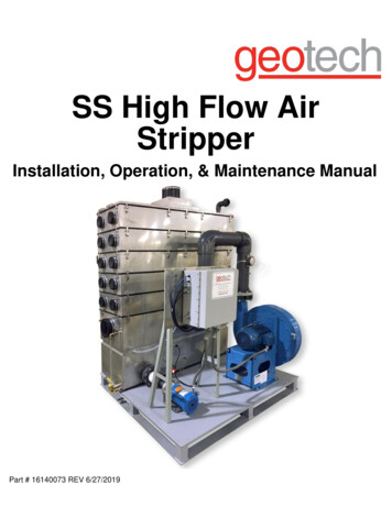
SS High Flow AirStripperInstallation, Operation, & Maintenance ManualPart # 16140073 REV 6/27/2019
Table of ContentsSection 1: SS High Flow Air Stripper Process. 3The SS High Flow Air Stripper Treatment Process . 4The SS High Flow Air Stripper Basic System . 4SS High Flow Air Stripper Accessory Options . 6Section 2: Operating Instructions . 11Special Precautions . 11Equipment Set-Up. 11Initial System Start Up. 16Routine Operation . 17Section 3: Cleaning Procedures . 18Equipment Required . 18System Shut Down . 18Cleaning the Unit: . 18Section 4: Trouble Shooting . 20Section 5: Components List, Drawings, & Cutsheets . 25AERATION PROCESS, COUNTER-CURRENT AIR AND WATER FLOW . 25Troubleshooting Guide for Poor Removal . 26TYPICAL VENT LINE INSTALLATION. 27SEALPOT FUNCTION - WATER SEAL . 30AIR PRESSURE GAGE. 33Section 6: Replacement Parts . 36The Warranty. 422
DOCUMENTATION CONVENTIONSThis uses the following conventions to present information:An exclamation point icon indicates a WARNING of a situation or condition that couldlead to personal injury or death. You should not proceed until you readand thoroughly understand the WARNING message.WARNINGA raised hand icon indicates CAUTION information that relates to a situation or conditionthat could lead to equipment malfunction or damage. You should not proceed until youread and thoroughly understand the CAUTION message.CAUTIONA note icon indicates NOTE information. Notes provide additional or supplementaryinformation about an activity or concept.NOTE3
Section 1: SS High Flow Air Stripper ProcessThe SS High Flow Air Stripper Treatment ProcessThe purpose of air stripping is to remove dissolved volatiles from liquids. Such dissolved volatiles include radonand carbon dioxide removed from potable well water, volatile organic compounds (VOCs) removed fromcontaminated groundwater plumes, and VOCs removed from industrial process and wastewater treatmentstreams.The stripping mechanism of the proprietary SS High Flow Air Stripper is dependent on the flow of an influentliquid through a long, narrow channel on a discrete number of trays while subject to a countercurrent flow ofambient air at a fixed flowrate.The intense formation and rupture of billions of bubbles in the confined narrow path of water flowing countercurrent to multiple fresh air vents is a dynamic process that provides a mass transfer mechanism that displacesthe dissolved volatiles from the aqueous stream into the vapor stream.The SS High Flow Air Stripper mechanism is a proprietary process protected under U.S. Patent # 5045,215and 5,240,595.The SS High Flow Air Stripper Basic SystemSS High Flow Air Stripper systems are fabricated from 304L stainless steel, 316L stainless steel, or rotationallymolded polyethylene, and are provided with components to facilitate the requirements of the process, includingthe following:Forced Draft Versus Induced DraftForced Draft (F.D.) System: The blower is installed so that the air is fed under positive pressure into thestripper sump below the stripper trays. This arrangement is used when the maximum total blower dischargepressure (air stripper plus other downstream pressure losses) does not exceed 26” (56 cm) water column(w.c.) pressure for plastic strippers, or 32” (82cm) w.c. for stainless steel strippers.Induced Draft (I.D.) System: The blower is installed such that it pulls air into the stripper sump, up through thetrays, and into the blower inlet, thus subjecting the stripper interior to a slight vacuum. Removal efficiency is notchanged by this arrangement. The blower is therefore sized to provide the pressure drop required for the SSHigh Flow Air Stripper, plus the pressure drop required by downstream off gas treatment devices.High Water Flow Versus Low Water FlowDue to increased froth heights on the trays at higher flowrates, two water flow ranges are considered in thedesign of the basic system, Low Flow and High Flow. The high flow system requires a blower that produces anadditional 4” (10.2 cm) w.c. pressure drop across the stripper as compared to the low flow system blower. TheLow and High water flow ranges for each SS High Flow Air Stripper series are listed in Table 1-1 below:4
SS High Flow Air Stripper SeriesLow Water Flow RangeHigh Water Flow Range1300P0.5 - 15 gpmN/A13000.5 - 15 gpm16 - 22.5 gpm2300P1 – 30 gpm31 - 50 gpm23001 - 30 gpm31 - 45 gpm26002 - 60 gpm61 - 115 gpm36003 - 90 gpm91 - 160 gpm312004 - 150 gpm151 - 425 gpm412006 - 200 gpm201 - 550 gpm6120012 - 350 gpm351 - 1000 gpm8120016 - 540 gpm541-1300 gpmTable 1-1: Low and High Water Flow Ranges for SS High Flow Air Stripper SeriesBasic System ComponentsComponents information sheets (“cut sheets”) can be found in Section 5: Components List, Drawings, &Cutsheets.BlowerThe blower supplied with the SS High Flow Air Stripper unit is typically type B spark resistant with a castaluminum wheel, direct driven @ 3450 rpm, with motor options of Totally Enclosed Fan Cooled (TEFC) orExplosion Proof (EXP), as determined by the power available and electrical code classification of the site.Each blower is selected to provide air flow that exceeds the minimum standard cubic feet per minute (SCFM)air flow required at the required working pressure (inches of w.c.) of the system. It is important that the blowerdamper be set to provide the unit with the required fresh air flow.It is also important that water not enter the blower housing while the blower is in operation; this will damage theblower and void the warranty. During normal operation, the high water level alarm switch prevents this fromhappening. Confirm that this switch is installed properly.The installed motor horsepower is selected to provide an operating range with a significant safety margin.However, there is the potential for the blower motor to overload if it is not working against sufficient pressuredrop. Therefore, the blower must be protected with a thermal overload switch.The blower damper should be set so that the blower produces the minimum stripper air flow requirement (seeTable 1-2 below), and at the same time the motor does not exceed its nameplate amperage maximum.Air Flow DamperThe stripper blower is fitted with an adjustable damper, used to make air flow rate (SCFM) adjustments to thestripper. Open the damper to increase air flow rate, and close the damper to decrease air flow rate. Note thatair pressure may vary as the air flow rate is changed. To get an accurate air flow measurement, install an airflow meter in the air duct.If air flow meter installation is not possible, an estimated air flow can be obtained by measuring the stripperpressure drop. At initial start-up, adjust the damper until the air pressure is at the minimum required for thesystem. (Refer to the pressure gauge description for minimum pressure readings).Be aware that when making damper adjustments after the system has been operating, fouling may occur in thesystem, which may reduce the air flow rate and may increase the air pressure reading.5
Table 1-2 gives the minimum and maximum airflow rate for each SS High Flow Air Stripper series:SS High Flow Air Stripper SeriesAir Flow MinimumAir Flow Maximum1300 & 1300P150 SCFM (255 m3/hr)180 SCFM (305 m3/hr)2300 & 2300P300 SCFM (510 m3/hr)360 SCFM (610 m3/hr)2600600 SCFM (1020 m3/hr)720 SCFM (1220 m3/hr)3600900 SCFM (1530m3hr)1080 SCFM (1830 m3/hr)312001800 SCFM (3060 m3/hr)2160 SCFM (3670 m3/hr)412002400 SCFM (4080 m3/hr)2880 SCFM (4900 m3/hr)612003600 SCFM (6120 m3/hr)4320 SCFM (7340 m3/hr)812004800 SCFM (8155 m3/hr)5760 SCFM (9785 m3/hr)Table 1-2: Min and Max Airflow Rate for SS High Flow Air Stripper seriesMist EliminatorA wire mesh mist eliminator is installed beneath the air exhaust port, located on the top cover of the SS HighFlow Air Stripper. The purpose of the mist eliminator is to remove water droplets that would have blownthrough the vent line. It is possible, though unlikely, that the mist eliminator may become plugged or fouled. Ifthis occurs, the mist eliminator is easily removed for cleaning. Disconnect the vent line, take off the top cover,and remove the retaining plates on the bottom of the cover. The mist eliminator can be cleaned with a pressurewasher, or replaced with a new one.GasketA black nitrile (or neoprene on the 2300-P) sponge is used to form an airtight/watertight seal between the sumptank, cover, and stripper trays. A replacement gasket can be glued to the sealing flange using an industrialcontact adhesive. Please contact Geotech prior to making any gasket repairs or adjustments.Sight TubeThe sight tube provides a means of visually monitoring the water level in the sump tank. Make sure the valve tothe sight tube is open during stripper operation.Inlet Dip Tube / Spray NozzleAn inlet spray nozzle is only installed upon request. The dip tube directs the influent water to the top tray inletchamber.System performance is based on SS High Flow Air Stripper operation without a nozzle, and theperformance warranty is valid whether a nozzle is installed or not.SS High Flow Air Stripper Accessory OptionsSS High Flow Air Stripper System OptionsSS High Flow Air Strippers are custom built to meet site and project specifications. Please refer to Section 5:Components List, Drawings, & Cutsheets to see which options were selected for this system.6
Air Blower SilencerAn air blower silencer can reduce the noise level of the blower. The size of the silencer and the type ofconnection used to mount it are dictated by the size of the blower, and whether the silencer is mountedhorizontally or vertically. Silencers should be supported to avoid over-stressing the connections, and should besecured if exposed to high wind loads.Air Flow MeterAn air flow meter measures the amount of air flowing through the system. It consists of a pitot tube mounted inthe air duct and connected via two (2) lengths of tubing to a differential pressure gauge. The measured velocitypressure can be converted to an airflow velocity. The pitot tube must be located at least 8 1/2 pipe diametersdownstream of any pipe fitting or transition, and at least 1 1/2 diameters of straight pipe upstream of the end ofthe duct or any elbow. The best pitot tube location is before the stripper because the air is less humid and thegauge tubing is less likely to fill with condensate.The air flow meter typically gives readings in inches of water column, (w.c.), which is converted to feet perminute (FPM) using the provided chart or the gauge scale calibrated for the specific duct inside diameter. Asstated in the damper section, the air flow meter in conjunction with the pressure gauge provides the mostaccurate damper adjustments, especially after initial start-up.Table 1-3 lists the minimum vapor exhaust duct diameters.Stripper SeriesMinimum Exhaust Duct Diameter13006 “Ø (16 cm)23006 “Ø (16 cm)26008 “Ø (20 cm)360010 “Ø (25 cm)3120016 “Ø (40cm)4120018 “Ø (45cm)6120018 “Ø (45cm)8120018 “Ø (45cm)Table 1-3: Minimum Exhaust Duct DiameterRestricted airflow is the most common cause of poor removal efficiencies. An airflow meter ishighly recommended to help ensure adequate air flow.Air Pressure GaugeThe air pressure gauge reads the pressure differential across the stripper trays in inches of water column(w.c.). The gauge is connected to the system via tubing that attaches to a pressure port on the system.Instructions to connect the gauge for the types of systems are as follows:Forced Draft SystemUsing tubing, connect the “High” pressure port on the gauge to the 1/8”Ø (3mm) shutoff valve/hose barblocated on the air stripper sump. The “Low” pressure port on the gauge is left open to the atmosphere. Thehighest pressure drop is between the sump tank and the surrounding atmosphere.7
Induced Draft SystemUsing tubing, connect the “Low” pressure port on the gauge to the hose barb located on the exhaust vent lineon the air stripper. The “High” pressure port on the gauge is left open to the atmosphere. The highest pressuredrop (vacuum) is between the cover exhaust and the surrounding atmosphere.There are two pairs of pressure ports on the gauge, one pair for side entry, the other pair for rearentry. One pair should be used to measure the differential pressure, and the other unused pairmust be sealed with a plug.At initial start-up, the pressure gauge can be used to measure blower damper adjustments. Adjustmentsshould be made according to the following nominal differential air pressure table:Nominal Differential Air PressureNumber of trays1 tray system2 tray system3 tray system4 tray system5 tray system6 tray systemLow Water Flow SysHigh Water Flow System4-6 in. w.c. (10-15 cm.)7-10 in. w.c. (18-25 cm.)7-10 in. w.c. (18-25 cm.)11-14 in. w.c. (28-36 cm.)11-14 in. w.c. (28-36 cm.)16-18 in. w.c. (40-46 cm.)16-18 in. w.c.(40-46 cm.)20-22 in. w.c. (50-56 cm.)20-22 in. w.c. (50-56 cm.)24-26 in. w.c. (60-66 cm.)24-26 in. w.c. (60-66 cm.)28-30 in. w.c. (71-76 cm.)Table 1-4: Nominal Differential Air PressureThe nominal differential pressures shown are for the air stripper pressure drop only, and do notinclude additional air stream equipment pressure requirements.After initial start-up, fouling may occur in the system, which may increase the nominal air pressure reading, andmay decrease the airflow rate.Control PanelThe control panel serves two basic functions for operation of the system. The first is to provide the necessarystarting and circuit protection components for each motor load, consistent with NEC electrical code. Thesecomponents include fuses, circuit breakers, motor starter contactors, overload relays, and lock-out/tag-out(LOTO) features.The second function is to provide process control and alarm status/interlock components. Alarm circuitmonitors several conditions, most basically the low air pressure alarm switch and the high water level alarmswitch. If either of these alarms occurs, the alarm interlock will provide shut off signal to the incoming watersource (feed or well pumps), if the appropriate interconnects have been made. Other alarm options are alsoavailable.Control Panel: Intrinsically-Safe (I.S.) ComponentsSS High Flow Air Stripper systems that operate in or near potentially explosive concentrations of vapors willrequire special hardware to meet code requirements for power wiring and for instrument and switchconnections. In such cases, intrinsically safe (I.S.) isolation of signals to and from switches and instruments isemployed to limit the energy to a level lower than the energy required to generate a spark. Typical componentsthat need I.S. protected signals are float switches and well probes. Determination of when I.S. signals arerequired is the responsibility of the design engineer with knowledge of the site-specific code requirements.8
Digital Water Flow Indicator/TotalizerWater flow meters with totalization are often supplied as part of the SS High Flow Air Stripper. Available inseveral designs and sizes, flowmeters are typically installed in the water feed piping to the stripper, and usuallyprovide a local readout of flowrate (gpm) and the totalized flow (gallons). Refer to the components list insertSection 5: Components List, Drawings, & Cutsheets to see which flowmeter was provided with this system.Flowmeters are sensitive mechanisms that require proper care and maintenance for reliable service. It isprudent to install a strainer or bag filter upstream of the flowmeter to protect it from mechanical damage fromdebris in the pipeline. If the strainer and/or flowmeter become plugged, disassemble and clean in accordancewith the manufacturer’s instructions.Feed and Discharge PumpsIf pump(s) are included by Geotech as part of your system, they have been selected to meet the required flowand pressure requirements. The pumps are typically end suction, flooded inlet, direct coupled, centrifugalpumps, with either EXP or TEFC motors. The pumps are not self- priming. Prior to initial start-up, the pumpsmust be primed by filling the pump impeller housing with clean water. Throttling valves are typically installed onthe effluent pump discharge. If the pump is running wide open and it is not pumping against the required head,the pump may cavitate. This is the nature of centrifugal pumps; they must be throttled back if they are notpumping against the required head. The valve should be throttled until the motor amperage is less than thenameplate motor amps rating.Before system start-up, it is important to check for proper rotation of the impeller. A pump rotating in the wrongdirection could cause the pump impeller to spin off, causing serious damage to the pump.Systems using discharge pumps must have the flow rates balanced so that the discharge flow rate is greaterthan the inlet flow rate.Refer to the components list insert (Section 5: Components List, Drawings, & Cutsheets) to see which pump(s)were provided with this system.High Water Level Alarm Float SwitchThe high water level alarm float switch is one of the alarm sensors that must be connected prior to systemstart-up. The purpose of the high water level alarm float switch is to sense an excessively high level of water inthe stripper sump, and provide a signal to communicate to the upstream water source to shut off the incomingwater. The high water level float switch is a normally closed micro-switch that opens when the float risesapproximately 3 1/2" (9 cm) above its coupling's centerline.Component information cut sheets for the float switch are included in Section 5: Components List, Drawings, &Cutsheets of this manual.Line Sampling PortsLine sampling port(s) (when included) are provided to take water samples of incoming contaminated water andoutgoing clean water. The sampling ports are typically 1/2” (1 cm) ball valves.When taking a water sample, open the valve and let the water flow for at least 1 minute prior to bottling thesample. This purges the sample port of any stagnant water.When purging the sample ports be sure to capture the water and properly dispose of it. When starting the unitfor the first time double check that the valves on the sample ports are closed.9
Low Air Pressure/Vacuum Alarm SwitchThe low air pressure/Vacuum alarm switch monitors the blower for continuous water treatment. This switch isone of the alarm interlocks that must be properly connected by a licensed electrician prior to the system’s initialstart-up. Please see “Special Precautions” at the beginning of Section 2: Operating Instructions for moreinformation.Should the blower fail, the low air pressure switch is wired to shutoff all incoming water. Using tubing, connectthe switch to the hose barb on the tank (pressure system) or the hose barb in the cover exhaust duct (vacuumsystem).Pressure systemThe air hose is connected from the sump rank 1/8 “ (3 mm) hose barb (without valve) to the “high” pressureport on the switch using the provided hose barb. The “low” pressure port must be open to the atmosphere. Theswitch measures the differential pressure between the sump tank and the atmosphere.Vacuum systemThe air hose is connected from the exhaust piping 1/8” (3 mm) hose barb to the “low” pressure port on theswitch using the provided hose barb. The “high” pressure port must be open to the atmosphere. The switchmeasures the differential pressure between the top tray and the atmosphere.Periodically inspect the air hose for water build-up, which will affect the switch’s operation. The tubing mustremain open at all times.Test the switch at initial start-up by removing the air hose from the hose barb on the sump tank or exhaust pipeonce the system is in full operation. This should set the system into an alarm condition and shut off theincoming contaminated water.High Air Pressure/Vacuum Alarm SwitchThe high air pressure/vacuum alarm switch prevents the system from exceeding its highest ratedpressure/vacuum value. If the blower has the ability to produce pressure/vacuum higher than 32” (82 cm) W.C,for stainless units or 26” (56 cm) W.C. for plastic units then it should have a high pressure/vacuum alarmswitch. Be sure to check that the set point for alarm shutdown is at the proper setting for the system.Panel Disconnect SwitchThe panel disconnects switch removes power from the SS High Flow Air Stripper control panel. Make sure aqualified licensed electrician installs the power supply into the disconnect switch. Be sure to ground the switchto the main service ground.Water Temperature GaugeWater temperature gauges can be installed on both the inlet and outlet piping. Influent water temperature is animportant variable affecting the system’s removal efficiency.Water Pressure GaugeWater pressure gauges can be installed on both the inlet and outlet water piping. Excessively high readingscould signal that something in the piping system is plugged. Large pressure fluctuation could be a sign that thewater flow rate is varying.10
Section 2: Operating InstructionsSpecial PrecautionsIt is important that a qualified licensed electrician perform these installations.The following operations must be carried out prior to initial system start-up:1. Connect the Interlock switches. High Water level Interlocko If the water level in the sump tank rises beyond the maximum level, it could flood the blower.o This may damage the blower and void the warranty.o The high water level interlock switch is used to shut off the feed water pump in an emergencysituation. Low Air Pressure/Vacuum Interlocko If the blower fails, untreated water could be discharged. The low air pressure/vacuum interlockswitch will shut off the feed water pump to prevent additional water from entering the stripper. High Air Pressure/ Vacuum Interlocko If the system has a blower capable of producing more than 32” (82 cm) of water column (w.c.)for a stainless stripper or more than 26” (56 cm) w.c. for a polyethylene stripper, then thesystem requires a high pressure/vacuum switch.o If a unit fouls or pressure increases due to off-gas treatment, it may exceed the maximumpressure rating of the system and cause damage to the gaskets, sump, or trays.2. Fill the Sump Tank and each tray’s inlet Chamber. On initial start-up the sump tank must be filled with clean water to a height of about 5” (13 cm). Make sure the valve to the sight tube is open. The sump tank can be filled via the clean-out ports on the end of the stainless units, or through the inletwater port located on the cover. The inlet chamber on each tray (referred to as seal pots) can be filled manually by pouring clean waterthrough the 1” (3 cm) inlet chamber filling ports, or the 4” (10 cm) clean out ports located on the ends ofthe stainless units, or by disassembling the plastic units and filling the seal pots as you reassemble. The seal pots on both the plastic and stainless systems can also be filled at initial start-up byconnecting a clean water line to the inlet water port and running the system for ten minutes with theblower on and the damper 1/4 open. For complete instructions on this method, please follow initial Start-up procedures later in this section.Do Not Run Free-Product Through the SS High Flow Air Stripper Air Stripper.Free product contaminates the unit by coating the side walls with a film of free-product. SS High Flow AirStripper units are designed to remove dissolved VOC’s only.Fresh air is required for the system air intake. Air that is heavily contaminated with VOC’s will significantlyreduce the SS High Flow Air Stripper’s performance.Equipment Set-Up Drawings.o Drawings referred to in the following sections are located in Section 5: Components List,Drawings, & Cutsheets. Follow codes.11
oThe plumbing and electrical installations must be performed by qualified personnel, and must bedone in accordance with local, state, and national codes. Protect critical items from the environment.o In areas that could be below freezing, the stripper should be installed in a heated building.Plastic units, control panels, and motors should be protected from direct sun.o Explosion-proof motors should be protected from rain due to the absence of motor gaskets. Install adequate supports.o Since none of the external piping associated with the SS High Flow Air Stripper unit is designedto support process water lines or air piping, adequate supports must be installed. Assemble Unit.o All SS High Flow Air Stripper units are assembled and hydraulically tested at the factory.However, to safeguard the units from shipping damage, some components are removed prior toshipping and will require reassembly.o Follow all relevant steps in this section to set-up the SS High Flow Air Stripper system. Check for loose fittings.o Shipping the system to the site may have caused pipe joints or assembly hardware to loosen.o Re-tighten as necessary. Bolt unit together.o For shipping purposes, the SS High Flow Air Stripper unit may come in two sections; the blowerskid assembly and the sump and tray skid assembly.o Bolt the base frames together using the bolts and spacers provided. This step is done at the factory for the 1300 and 2300 series. Connect Blower.o For forced draft (F.D., or positive pressure) systems, install the provided rubber coupling toconnect the blower outlet to the air inlet on the sump tank. (See Section 5: Components List,Drawings, & Cutsheets coupling layout drawing for air inlet location.)o For induced draft (I.D., or vacuum) systems, install an exhaust duct from the stripper air exhaustlocated on the top cover to the blower intake.o Make sure the pipe diameter is large enough to maintain the required airflow without adding apressure drop.o Also, be sure the pipe has a suitable vacuum rating to prevent collapse.Blower must draw air. Do not vent storage tanks that contain substances that will contaminate theair in the same room the blower draws air from. Do not duct intake air from an area that hascontaminated air. Contaminated air will contaminate the water Assemble trays and level the SS High Flow Air Stripper unit.o Large SS High Flow Air Strippers may have the top tray and cover shipped separately.o Install trays shipped separately by lining up the match-marked arrows and numbers on the traysand cover. To prevent damaging the gasket, do not drag the trays or cover across the gasket duringassembly.o Fasten all latches properly. The tray being installed must have the downcomers from each upper tray line up withthe sealpots on the tray below.o Check all the trays to make sure they are installed correctly, and not backwards. If the system is not set up properly, the water could bypass a tray allowing water to miss12
oo a large portion of the treatment path.Refer to the “basic subassembly” exploded view drawing in Section 5: Components List,Drawings, & Cutsheets.Level the SS High Flow Air Stripper. This is a critical step in the proper assembly of the equipment. If not level, the water depth on the trays will be uneven, causing the water to weepthrough the tray holes untreated.For a gravity discharge unit (no discharge pump): Install the outlet pipe.o The plumbing components are typically shipped in a separate box.o Refer to Section 5: Components List, Drawings, & Cutsheets for outlet piping drawings toassemble.F.D. systems require a riser pipe (inverted U-trap) to compensate for the pressure generated by the blower. Itis important that the riser pipe height be adjusted to create a 5” (13 cm) water depth in the sump tank duringnormal operating conditions. The provi
design of the basic system, Low Flow and High Flow. The high flow system requires a blower that produces an additional 4" (10.2 cm) w.c. pressure drop across the stripper as compared to the low flow system blower. The Low and High water flow ranges for each SS High Flow Air Stripper series are listed in Table 1-1 below: