Transcription
Model 9000/9100/9500Service ManualIMPORTANT: Fill in pertinent information on page 3 for future reference.
Model 9000/9100/9500Table of ContentsJob Specifications Sheet . . . . . . . . . . . . . . . . . . . . . . . . . . . . . . . . . . . . . . . . . . . . . . . . . . . . . . . . . . . . . . . . . . . . . . . . . . . . . . . 3General and Commercial Installation Checklist . . . . . . . . . . . . . . . . . . . . . . . . . . . . . . . . . . . . . . . . . . . . . . . . . . . . . . . . . . . . . 4General and Commercial Installation Checklist . . . . . . . . . . . . . . . . . . . . . . . . . . . . . . . . . . . . . . . . . . . . . . . . . . . . . . . . . . . . . 6Regeneration Cycle Program Setting Procedure . . . . . . . . . . . . . . . . . . . . . . . . . . . . . . . . . . . . . . . . . . . . . . . . . . . . . . . . . . . . . 9Time Brine Refill and Meter Setting Procedure . . . . . . . . . . . . . . . . . . . . . . . . . . . . . . . . . . . . . . . . . . . . . . . . . . . . . . . . . . . . 10ET Timer Installation And Start-Up Procedures . . . . . . . . . . . . . . . . . . . . . . . . . . . . . . . . . . . . . . . . . . . . . . . . . . . . . . . . . . . . 12ET Timer Control Start-Up Procedure . . . . . . . . . . . . . . . . . . . . . . . . . . . . . . . . . . . . . . . . . . . . . . . . . . . . . . . . . . . . . . . . . . . 14ET Timer Control Operation . . . . . . . . . . . . . . . . . . . . . . . . . . . . . . . . . . . . . . . . . . . . . . . . . . . . . . . . . . . . . . . . . . . . . . . . . . . 15SE Timer Control Start-Up Procedures . . . . . . . . . . . . . . . . . . . . . . . . . . . . . . . . . . . . . . . . . . . . . . . . . . . . . . . . . . . . . . . . . . . 18ET and SE Timer Assemblies . . . . . . . . . . . . . . . . . . . . . . . . . . . . . . . . . . . . . . . . . . . . . . . . . . . . . . . . . . . . . . . . . . . . . . . . . . 219000/9100/9500 Electro Mechanical Timer Assembly . . . . . . . . . . . . . . . . . . . . . . . . . . . . . . . . . . . . . . . . . . . . . . . . . . . . . . . 229000/9100/9500 Power Head . . . . . . . . . . . . . . . . . . . . . . . . . . . . . . . . . . . . . . . . . . . . . . . . . . . . . . . . . . . . . . . . . . . . . . . . . . . 249000/9100/9500 Power Head . . . . . . . . . . . . . . . . . . . . . . . . . . . . . . . . . . . . . . . . . . . . . . . . . . . . . . . . . . . . . . . . . . . . . . . . . . . 259000 Control Valve Assembly . . . . . . . . . . . . . . . . . . . . . . . . . . . . . . . . . . . . . . . . . . . . . . . . . . . . . . . . . . . . . . . . . . . . . . . . . . 269100 Control Valve Assembly . . . . . . . . . . . . . . . . . . . . . . . . . . . . . . . . . . . . . . . . . . . . . . . . . . . . . . . . . . . . . . . . . . . . . . . . . . 289500 Control Valve Assembly . . . . . . . . . . . . . . . . . . . . . . . . . . . . . . . . . . . . . . . . . . . . . . . . . . . . . . . . . . . . . . . . . . . . . . . . . . 309500 Brine Valve Systems (1600 and 1700 Series) . . . . . . . . . . . . . . . . . . . . . . . . . . . . . . . . . . . . . . . . . . . . . . . . . . . . . . . . . . 319000/9100/9500 Second Tank Assemblies. . . . . . . . . . . . . . . . . . . . . . . . . . . . . . . . . . . . . . . . . . . . . . . . . . . . . . . . . . . . . . . . . 329000/9100/9500 Meter Assemblies . . . . . . . . . . . . . . . . . . . . . . . . . . . . . . . . . . . . . . . . . . . . . . . . . . . . . . . . . . . . . . . . . . . . . . 349000/9100 Bypass Valve . . . . . . . . . . . . . . . . . . . . . . . . . . . . . . . . . . . . . . . . . . . . . . . . . . . . . . . . . . . . . . . . . . . . . . . . . . . . . . 362310 Safety Brine Valve . . . . . . . . . . . . . . . . . . . . . . . . . . . . . . . . . . . . . . . . . . . . . . . . . . . . . . . . . . . . . . . . . . . . . . . . . . . . . . 379500, 2350 Safety Brine Valve . . . . . . . . . . . . . . . . . . . . . . . . . . . . . . . . . . . . . . . . . . . . . . . . . . . . . . . . . . . . . . . . . . . . . . . . . 382300 Safety Brine Valve . . . . . . . . . . . . . . . . . . . . . . . . . . . . . . . . . . . . . . . . . . . . . . . . . . . . . . . . . . . . . . . . . . . . . . . . . . . . . . 39Water Conditioner Flow Diagrams . . . . . . . . . . . . . . . . . . . . . . . . . . . . . . . . . . . . . . . . . . . . . . . . . . . . . . . . . . . . . . . . . . . . . . 40Troubleshooting . . . . . . . . . . . . . . . . . . . . . . . . . . . . . . . . . . . . . . . . . . . . . . . . . . . . . . . . . . . . . . . . . . . . . . . . . . . . . . . . . . . . . 44Mechanical Timer Valve Wiring . . . . . . . . . . . . . . . . . . . . . . . . . . . . . . . . . . . . . . . . . . . . . . . . . . . . . . . . . . . . . . . . . . . . . . . . 46ET Timer Valve Wiring . . . . . . . . . . . . . . . . . . . . . . . . . . . . . . . . . . . . . . . . . . . . . . . . . . . . . . . . . . . . . . . . . . . . . . . . . . . . . . . 47SE Timer Valve Wiring . . . . . . . . . . . . . . . . . . . . . . . . . . . . . . . . . . . . . . . . . . . . . . . . . . . . . . . . . . . . . . . . . . . . . . . . . . . . . . . 489000 Control Dimensions . . . . . . . . . . . . . . . . . . . . . . . . . . . . . . . . . . . . . . . . . . . . . . . . . . . . . . . . . . . . . . . . . . . . . . . . . . . . . 499100 Control Dimensions . . . . . . . . . . . . . . . . . . . . . . . . . . . . . . . . . . . . . . . . . . . . . . . . . . . . . . . . . . . . . . . . . . . . . . . . . . . . . 509500 Control Dimensions . . . . . . . . . . . . . . . . . . . . . . . . . . . . . . . . . . . . . . . . . . . . . . . . . . . . . . . . . . . . . . . . . . . . . . . . . . . . . 51Meter Flow Data . . . . . . . . . . . . . . . . . . . . . . . . . . . . . . . . . . . . . . . . . . . . . . . . . . . . . . . . . . . . . . . . . . . . . . . . . . . . . . . . . . . . 52Injector Flow Data . . . . . . . . . . . . . . . . . . . . . . . . . . . . . . . . . . . . . . . . . . . . . . . . . . . . . . . . . . . . . . . . . . . . . . . . . . . . . . . . . . . 54IMPORTANT: The information, specifications and illustrations in this manual are based on the latest information availableat the time of printing. The manufacturer reserves the right to make changes at any time without notice.
Model 9000/9100/9500Job Specifications SheetJob NumberModel NumberWater TestCapacity Of Unit Max. Per RegenerationBrine Tank SizeSalt Setting Per RegenerationControl Valve Specifications1.Type of TimerA. 82 minute available regeneration time, 1/15 RPMB. 164 minute available regeneration time, 1/30 RPM2.Type of MeterMeter3/4"1"1-1/2"Meter3/4"1"1-1/2"Mechanical Valves(gallon settings)Standard Range125–2,125310–5,270625–10,625Electrical Timers(minutes per cycle)ET(0–999.9 minutes per cycle)9,999,9999,999,9999,999,999Extended ��99 minutes per cycle)9,9999,999—3.Timer Gallon Setting gal.4.Regeneration Program SettingA. Backwash min.B. Brine and Slow Rinse min.C. Rapid Rinse min.D. Brine Tank Refill min.5.Drain Line Flow Control gpm6.Brine Refill Rate gpm7.Injector Size3
Model 9000/9100/9500General and Commercial Installation ChecklistWater PressureA minimum of 25 lbs of water pressure is required for regeneration valve to operate effectively.Electrical FacilitiesAn uninterrupted alternating current (A/C) supply is required. Make sure: Voltage supply is compatible with unit before installation. Current supply is always hot and cannot be turned off with another switch.Existing PlumbingCondition of existing plumbing should be free from lime and iron buildup. Replace piping that has heavy lime and/or ironbuild-up. If piping is clogged with iron, install a separate iron filter unit ahead of the water softener.Location of Softener and DrainLocate the softener close to a clean working drain and connect according to local plumbing codes.Bypass ValvesAlways provide for the installation of a bypass valve if unit is not equipped with one.CAUTION 4Do not exceed water pressure of 125 psi.Do not exceed 110 F water temperature.Do not subject unit to freezing conditions.
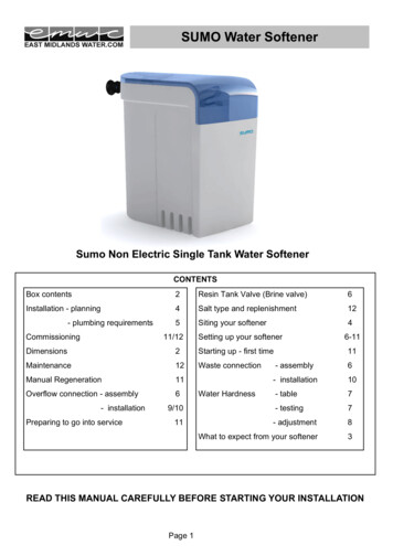
Model 9000/9100/9500Equipment Configuration9000/9100tank twoyokeswater metertank oneoutletinlettank two adapterbypass valvemain control valveadapter clipsFigure 1: 9000/910095001-1/2" copperoutletinletmeter domemust face uptank two adaptercontrol valvetank twoFigure 2: 95005
Model 9000/9100/9500General and Commercial Installation Checklist1.Place the softener tank where you want to install the unit.NOTE: Be sure the tank is level and on a firm base.2.During cold weather it is recommended that the installer warm the valve to room temperature before operating.3.Perform all plumbing according to local plumbing codes.— Use a 1/2" minimum pipe size for the drain.— Use a 3/4" drain line for backwash flow rates that exceed 7 gpm or length that exceeds 20′ (6 m).4.Both tanks must be the same height and diameter and filled with equal amounts of media.5.The distributor tube must be flush with the top of each tank. Cut if necessary. Use only non-aerosol silicone lubricant.6.Lubricate the distributor o-ring seal and tank o-ring seal. Place the main control valve on one tank and the tank adapter onthe second tank.NOTE: If required, solder copper tubing for tank interconnection before assembling on the main control valve and tankadapter. Maintain a minimum of 1" distance between tanks on final assembly.7.Solder joints near the drain must be done before connecting the Drain Line Flow Control fitting (DLFC). Leave at least 6"(152 mm) between the DLFC and solder joints when soldering pipes that are connected on the DLFC. Failure to do thiscould cause interior damage to DLFC.8.Use only Teflon tape on the drain fitting.9.Be sure the floor under the salt storage tank is clean and level.10. Place approximately 1" (25 mm) of water above the grid plate. If a grid is not utilized, fill to the top of the air check in thesalt tank. Do not add salt to the brine tank at this time.11. On units with a bypass, place in Bypass position.— Turn on the main water supply.— Open a cold soft water tap nearby and let water run a few minutes or until the system is free of foreign material(usually solder) resulting from the installation. Close the water tap when water runs clean.12. Place the bypass In Service position and let water flow into the mineral tank. When water flow stops, slowly open a coldwater tap nearby and let water run until air is purged from the unit. Then close tap.Electrical13. Make all electrical connections according to codes. Plug the valve into an approved power source. Do not insert metercable into the meter yet.14. Tank one has control valve and tank two has adapter. See Figure 1, page 5 or Figure 2, page 5.15. Look on the right side of the control valve, it has indicators showing which position the control valve is in duringRegeneration and which tank is In Service.— Figure 3, page 7 shows the valve In Service position with tank one supplying conditioned water and tank two onstandby.NOTE: Make sure the meter cable is not inserted in the meter dome. Swing the timer out to expose the program wheel (toswing timer out) grab onto the lower right corner of timer face and pull outward. See Figure 5, page 8.6
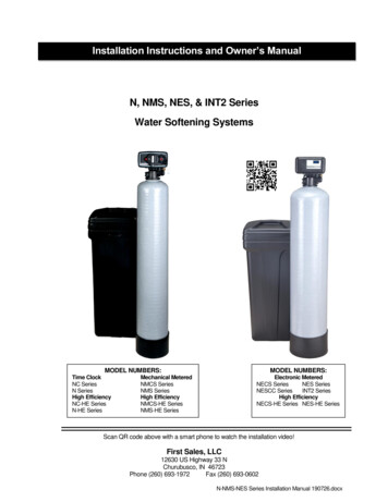
Model 9000/9100/9500rapid rinsebrine rinsebrine fillbackwashstand-bytank twotank oneFigure 3: Control Valve Position IndicatorsFigure 4: Timer16. Cycle timer into backwash position. Turn manual knob so that the micro switch rides on the first set of pins.— In this position the tanks switch (lower piston) and the control valve moves to the backwash position (upper piston).— Wait until the positioning of upper and lower pistons stops before advancing the timer further. If advanced too fastthe control will not home into the In Service position (it will not advance to any other position). To correct this, rotatethe manual knob back to In Service and start again into backwash.NOTE: Once valve positions itself into the backwash cycle, the homing circuit locks in.17. With all the air backwashed, slowly cycle the timer to the brine position; rapid rinse; and brine tank refill. Wait for thecontrol drive motor to position itself in each cycle and stop, before advancing on to the next position.18. Once back in the In Service position, cycle the control valve again into the backwash position. The tanks switch again,and air head backwashes out of the other tank. Cycle the control back to the In Service position. Leave the timer in theopen position. DO NOT insert meter cable yet.7
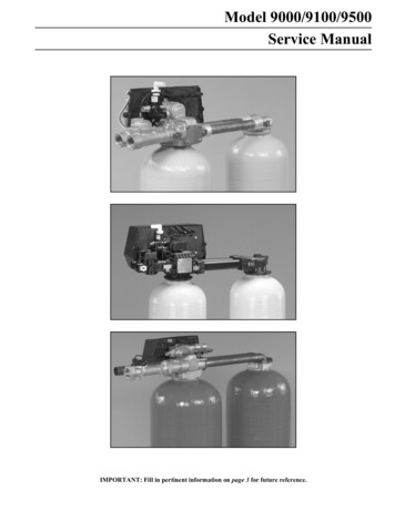
Model 9000/9100/9500pinstorageFigure 5: Program WheelNOTE: Two motors are available:1/15 RPM has 82 minute Regeneration Time.1/30 RPM has 164 minute Regeneration Time. See Figure 5.8
Model 9000/9100/9500Regeneration Cycle Program Setting ProcedureSetting the Regeneration Cycle ProgramThe Regeneration cycle program on the water conditioner is preset at the factory. However, portions of the cycle or programtime may be lengthened or shortened for local conditions or system design.1.Expose cycle program wheel by grasping timer in lower right hand corner and pulling. This releases snap retainer andswings timer to the leftNOTE: Meter cable must be removed from meter dome before opening timer.2.Remove the program wheel by grasping program wheel and squeezing protruding lugs towards center. Lift program wheeloff timer.— Switch arms may require movement to facilitate removal.3.Return timer to closed position by engaging snap retainer in back plate.— Make certain all electrical wires locate above snap retainer post.Changing Length of the Backwash TimeThe program wheel in Figure 5 is In Service position. Looking at the numbered side of the program wheel, the group of pinsstarting at zero determines the length of time the unit backwashes.Example: If there are six pins in this section, the time of backwash is 12 minutes (2 minutes per pin). To change thelength of backwash time, add or remove pins as required.— The number of pins multiplied by two equals minutes of backwash.Changing Length of Brine and Rinse TimeThe group of holes between the last pin in the backwash section and the second group of pins determines the length of timethat a unit will brine and rinse (2 minutes per hole).To change the length of brine and rinse time, add or remove pins in the rapid rinse group of pins to increase or decrease thenumber of holes in the brine and rinse section.— The number of holes multiplied by two equals minutes of brine and rinse.Changing Length Of Rapid RinseThe second group of pins on the program wheel determines the length of time the water conditioner rapid rinses (2 minutes perpin). To change the length of rapid rinse time, add or remove pins at the higher numbered end of this section as required.— The number of pins multiplied by two equals minutes of rapid rinse.NOTE: Program wheels with 0–82 minute cycle times, use one minute per pin or hole to set Regeneration times. Thelayout of pins and holes on the program wheel follow the same procedure as on this page.Changing Length of Brine Tank Refill TimeThe second group of holes on the program wheel determines the length of time the water conditioner refills the brine tank (2minutes per hole).To change the length of refill time, move the two pins at the end of the second group of holes as required.The Regeneration cycle is complete when the two pin set at end of the brine tank refill section trips the outer micro-switch.The program wheel, however, continues to rotate until the inner micro-switch drops into the notch on the program wheel.9
Model 9000/9100/9500Time Brine Refill and Meter Setting ProcedureProgramming1.The control valve is set at the factory for backwash; brine and slow rinse; rapid rinse and brine tank fill times. Change anyof these times by repositioning the pins and holes or adding more pins.NOTE: Two speed timer motors are available1/15 RPM has 82 minute Regeneration Time and each pin or hole equals one minute.1/30 RPM has 164 minute Regeneration Time and each pin or hole equals two minutes.2.The control valve has a separate brine tank fill cycle.— Calculate the desired salt setting using the brine line flow control rate of refill (in gpm) multiplied by the timersetting. Then, using one gallon of fresh water dissolving approximately 3 lbs salt, calculate the refill time.Example: A desired 30 lbs salt setting:The unit has a 1.0 gpm refill rate so a 10 gallon fill is required.10 gallons x 3 lbs/gals 30 lbs saltSet the timer refill section at 10 minutes.10 minutes x 1.0 gpm 10 gallon fillNOTE: There must always be two pins at the end of a refill time to stop the fill cycle.With the Regeneration times set, place timer back to its original position, making sure the lower right handcorner snaps back into the backplate and the meter cable slides through the backplate and does not bind.3.Setting the gallon wheel.Knowing the amount of resin in each tank and the salt setting per Regeneration, calculate the gallons available, using thefollowing capacities as a guide:(capacity per ft3 x ft3 of resin per tank)compensated hardness of H2O gallons availableNOTE: Based on tank size:More resin increases capacity, less resin decreases capacity.More salt increases capacity, less salt decreases capacity.Example:tank diametercompensated hardness ft3 resin (based on flow rate)lbs of salt 4 8capacity per ft3 24,000(24,000 x 4 ft3 of resin per tank)35 grains16"35 grains per gal (tested sample) 2740 gallons available before regenerationDO NOT SET THIS FIGURE - GO TO STEP 4— Because the control valve regenerates with soft water from the other tank, subtract the water used for Regeneration.Take each Regeneration cycle and calculate the water used.10
Model 9000/9100/9500Example: Unit is set for a 16" diameter tank with 4 ft3 of resin and salted at 8 lbs. per ft3, 7 gpm backwash, #3 injector,1.0 gpm brine refill, and 60 psi and timer set for 10 min. backwash, 60 min. brine and rinse, 10 min. rapidrinse, 10 min. brine tank fill.BackwashBrine and RinseRapid RinseBrine Tank Fill10 minutes x 7.0 gpm 60 minutes x 1.0 gpm 10 minutes x 7.0 gpm 10 minutes x 1.0 gpm 70.0 gallons60.0 gallons70.0 gallons10.0 gallonsTotal Regeneration Water 210.0 gallonsWith the 2740 gallons available calculated in Step 3, subtract the Regeneration water used from the totalwater available.2740 gallons available4.- 210 gallons used (in Regeneration, Step 4)2530 gallonsSet meter wheel at approximately 2530 gallons. Lift the inner dial of the meter program wheel so that you can rotate itfreely. Position the white dot opposite the 2530 gallon setting.NOTE: There is a slight delay between the time the meter zeros out and the cycle starts. Units using the:1/15 RPM motor, 82 minute Regeneration Time has a 9 minute delay1/30 RPM motor, 180 minute Regeneration Time has an 18 minute delay.This delay period is not critical on residential equipment. However, take this factor into consideration forcommercial applications by subtracting continuous flows for 9 minutes or 18 minutes from water available.5.Insert meter cable into meter.6.Check bypass.7.Plug in unit.11
Model 9000/9100/9500ET Timer Installation And Start-Up Procedures1.In Normal Operation the Time Of Day and, if flow meter equipped, the Volume Remaining displays appear alternately.Set the Time Of Day display. Press the Up or Down set button to display the correct time.Example:12:59 P.M.Valve In ServiceFigure 62.Flow Meter Equipped Valves Only: The Volume Remaining Display displays the volume of water in gallons (includingany reserve capacity) remaining prior to Regeneration. When there is no water usage the Meter arrow should not appearor not change. Open a soft water tap. The Meter arrow begins flashing at a rate that varies with flow rate. Close the tapafter 3–5 gallons of water flow.Example:0 gallons of water remainingValve In ServiceWater flowingVolume below reserve capacityReserve arrow flashingExample:125 gallons of water remainingValve In ServiceNo water flowVolume below reserve capacityReserve arrow flashingFigure 73.Manually initiate a Regeneration cycle and allow water to run to drain for 3 to 4 minutes. Press and release the ExtraCycle button. With Immediate Regeneration timers the control goes into Regeneration immediately. With DelayedRegeneration timers the In Service arrow flashes immediately and a Regeneration occurs at the preset RegenerationTime. Press and hold the Extra Cycle button for 5 seconds. The control goes into Regeneration immediately.4.Manually step the valve through a Regeneration cycle, checking valve operation in each step. During Regeneration thecontrol displays the Regeneration step number to which the valve is advancing or has reached and the time remaining inthat step.12
Model 9000/9100/9500Example:Valve advancing to Regeneration Step #1#1 flashingRegeneration arrow onBackwashFigure 8— When the first cycle step is reached, a red LED turns on indicating the current Regeneration cycle step.Example:Regeneration Step #1 reached10.0 minutes remain in Step #1Regeneration arrow onBackwashFigure 9— Press the Extra Cycle button during a Regeneration step to immediately advance the valve to the next Regenerationstep position.— Press the Up or Down set buttons during a Regeneration step to adjust the time remaining in the currentRegeneration step. Programmed Regeneration step times are not changed.— Once all Regeneration cycle steps are complete, the valve returns to In Service and resumes normal operation.5.Manually step the valve to the Brine Draw position (see Step #15) and allow the valve to draw water from the brine tankuntil it stops.*NOTE: The air check checks at approximately the midpoint of the screened intake area.6.Manually step the valve to the Brine Refill position and allow the valve to return to In Service automatically.7.Make sure the brine refill time (salt dosage) is set as recommended by the manufacturer.8.With the valve In Service, check that there is about 1″ of water above the grid in the brine tank, if one is used.9.Fill the brine tank with salt.NOTE: It is recommended a 9V Alkaline Battery be installed at all times for proper valve operation. The Low BatteryLED turns on when the battery needs to be replaced.13
Model 9000/9100/9500ET Timer Control Start-Up ProcedureDisplay ETService IndicatorValve In Service, Arrow OnManual Regeneration Tonight, Flashing ArrowTime of Day IndicatorReserve IndicatorVolume Remaining Above Reserve, Arrow OffVolume Remaining At or Below Reserve, Arrow FlashingTotalizer IndicatorFlow IndicatorNo Water Flow, Arrow OffWater Flow, Arrow FlashingSensor IndicatorSensor Input Signal, Arrow FlashingValid Regeneration Signal, Arrow OnFlow Rate IndicatorProgram IndicatorVolume Remaining IndicatorLockout IndicatorLockout Signal, Arrow OnRegeneration IndicatorValve in Regeneration, Arrow OnFigure 10: ET Timer DisplayIn Normal operation the Time Of Day display alternates with the Volume Remaining display. The meter arrow flashes indirect relation to the water flow rate through the unit. As treated water is used, the Volume Remaining display counts downfrom a maximum value to the calculated reserve capacity. The Reserve arrow flashes when the reserve capacity is being used.At the preset Regeneration Time, a Regeneration cycle initiates.Example:125 gallons of water remainingValve In ServiceNo water flowVolume is below reserve capacityExample:0 gallons of water remainingValve In ServiceWater flowingMeter arrow flashingVolume is below reserve capacityFigure 1114
Model 9000/9100/9500ET Timer Control OperationTimeclock Regeneration ValvesWhen the number days since the last Regeneration reaches the preset number of days, a Regeneration cycles initiates at thepreset Regeneration Time.Flow Meter Equipped Immediate Regeneration ValvesThe Time Of Day display alternates with the Volume Remaining display. The Meter arrow flashes in direct relation to thewater flow rate through the unit. As treated water is used, the Volume Remaining display counts down from a maximumvalue to zero and initiates a Regeneration cycle.Example:525 gallons of water remainingValve In ServiceWater flowingMeter arrow flashingFigure 12Sensor Immediate Regeneration ValvesWhen the control receives a valid sensor input signal, a Regeneration cycle initiates. The Sensor Input arrow flashes until thesignal is determined to be valid.Sensor Delayed Regeneration ValvesWhen the control receives a valid sensor input signal, a Regeneration cycle initiates at the preset Regeneration Time. TheSensor Input arrow flashes until the signal is determined to be valid. The Reserve arrow flashes when the reserve capacity isbeing used.Example:12:58 A.M. with invalid sensor signalValve In ServiceSensor arrow flashingExample:12:59 A.M. with valid sensor signalValve In ServiceSensor arrow onReserve arrow flashingDelayed regenerationFigure 13Lockout Input OperationThe lockout arrow turns on whenever the control sends a lockout signal. Any requests for Regeneration are delayed until thissignal is removed. Regeneration then proceeds normally.15
Model 9000/9100/9500Figure 14Start an Extra CyclePress the Extra Cycle button to start an Extra Regeneration tonight. Press and hold the Extra Cycle button for 5 seconds tostart an Extra Cycle immediately.Totalizer/Flow RatePress the Totalizer Flow Rate button to display the flow rate.Press the button a second time to display the total accumulation of water flow through the valve since the last reset.Press the button a third time to return the display to Time Of Day or Volume Remaining.— Press and hold the button for 25 seconds to reset the Totalizer display. During the 25 seconds, the Totalizer arrowflashes indicating that the display is resetting properly.Low Battery IndicatorFigure 15The red Low Battery LED turns on whenever the 9V Alkaline Battery (not included) requires replacement. The battery is usedfor memory backup and is stored against the valve backplate. In the event of a power outage, the battery maintains the currentoperating displays for approximately 24 hours at maximum battery capacity.Immediate Regeneration Valves With Days Between Regeneration Override SetWhen the valve reaches its set Days Since Regeneration Override value, a Regeneration cycle initiates immediately. Thisevent occurs regardless of the Volume Remaining display reaching zero gallons.Delayed Regeneration Valves With Days Between Regeneration Override SetWhen the valve reaches its set Days Since Regeneration Override value, a Regeneration cycle initiates at the presetRegeneration Time. This event occurs regardless of the Volume Remaining display reaching the calculated reserve capacity.Control Operation During RegenerationIn Regeneration the control displays a special Regeneration display. The control shows the current Regeneration stepnumber to which the valve is advancing or has reached, and the time remaining in that step. The displayed step number flashesuntil the valve completes driving to the Regeneration step position. Once all Regeneration steps are complete the valvereturns to In Service and resumes normal operation.Example:Less than 10 minutes remaining inRegenerationStep #1BackwashFigure 1616
Model 9000/9100/9500Press the Extra Cycle button during a Regeneration cycle to immediately advances the valve to the next cycle step positionand resume normal step timing.Control Operation During ProgrammingThe control enters Program Mode with the valve In Service. While in Program Mode the control continues to operatenormally, monitoring water usage and keeping all displays up to date. Control programming is stored in memory permanently.There is no need for battery backup power.Control Operation During A Power FailureDuring a power failure all control displays and programming are stored for use upon power re-application. The control retainsthese values for years, if necessary, without loss. The control is fully inoperative and any calls for Regeneration are delayed.The control, upon power re-application, resumes normal operation from the point that it was interrupted. An inaccurate orflashing Time of Day display indicates that a power outage has occurred.17
Model 9000/9100/9500SE Timer Control Start-Up ProceduresDisplay SEFigure 17: SE Timer DisplayIn normal operation the Time Of Day display alternates with Volume Remaining and Tank in In Service displays (9000SETimer only). As treated water is used, the Volume Remaining display counts down (in gallons) from a maximum value to zeroor (----). Once this occurs a Regeneration cycle initiates immediately or delayed to the set Regeneration Time. Water flowthrough the valve is indicated by the flashing Flow Dot Indicator.Figure 18: SE Timer Display During Normal OperationSet Time of DayWhen the valve is In Service, press either the Set Up or Set Down button once to adjust the Time Of Day by one digit. Pressand hold to adjust by several digits.Start an Extra Regeneration CyclePress the Extra Regeneration button to start an Extra Regeneration tonight. Press and hold the Extra Regeneration buttonfor 5 seconds to start an Extra Regeneration immediately.18
Model 9000/9100/9500Set Control Programming1.Press and hold both the Set Up and Set Down buttons for 5 seconds.2.Set the Treated Water Capacity. Using the Set Up or Set Down buttons, set the amount of treated water to flow throughthe unit before a Regeneration is required.3.Press the Extra Regeneration button.4.Set the Regeneration Time. Use the Set Up or Set Down buttons to set the desired time of day for Regeneration tooccur.NOTE: This does not display if Regeneration occurs immediately.5.Press the Extra Regeneration button.6.Set Regeneration Day Override. Use the Set Up or Set Down buttons to set the
— Turn on the main water supply. — Open a cold soft water tap nearby and let water run a few minutes or until the system is free of foreign material (usually solder) resulting from the installation. Close the water tap when water runs clean. 12. Place the bypass In Service position and let water flow into the mineral tank. When water flow .