Transcription
Bulletin 40-30 / May 2007Component LayoutGENERALThis manual, when used in conjunction with Bulletin 40-40,System Sizing and Layout should provide the necessaryinformation to determine the UNICO SYSTEM sizing, layoutand job material list. The many specification and installationinstructions for the UNICO SYSTEM equipment should bestudied so the system designer understands the equipmentthoroughly before proceeding with the system design andlayout.SYSTEM SIZINGBefore the proper equipment can be selected for a UNICOSYSTEM installation, it is imperative that the heat gain and/orheat loss be calculated for the structure that is to be comfortconditioned. To assure a proper layout and a well-balancedsystem, room by room heat gain and/or heat losses shouldbe calculated using generally recognized methods, such asACCA Manual J or the ASHRAE Cooling and Heating LoadCalculation Manual. The extra time spent designing aproper system will be repaid many times and result in:1. Correctly sized equipment2. Properly balanced system3. Less call backs4. Satisfied customers5. More profitNote: It is permissible to use shorter and quickerprocedures for job estimating purposes. These are coveredin a separate instruction. However, it is important toremember that such procedures are for the initial costestimates and are no substitute for the more detailed longerprocedures as outlined above.EQUIPMENT SELECTIONUnico, Inc. air handlers are available in three (3) basicmodels in the ‘M’ series. The M1218 provides a smallcompact unit in one package for 1 and 1-1/2 ton coolingsystems. The M series modular air handling units areavailable in 3 sizes, the M2430 for 2 and 2-1/2 ton coolingsystems, the M3642 for 3 and 3-1/2 ton cooling systems,and the M4860 for 4-5 ton cooling systems. All air handlersare available as cooling only (either DX or chilled water),heat pump with auxiliary electric heating and hot water coilheating.EQUIPMENT LOCATIONAll UNICO SYSTEM air handlers can be installed in thehorizontal and vertical upflow configurations. Additionally, Copyright 2007 Unico, Inc.the modular units (M2430, M3642, and M4860) can beinstalled in the vertical downflow configuration. Theinstallation possibilities are:A. Horizontal Units:1. Attic installation supported on a platform orsuspended from attic rafters.2. Basement installation suspended from the floorjoists.3. Furred down installation in hallways, closets orutility rooms.B. Vertical Upflow Units:1. Closet or utility room installation on a cabinetbase or wall brackets.2. Basement installation on a cabinet base orplatform.C. Vertical Downflow Units:1. First floor closet or utility room installationover a crawl space or slab (requires specialconsideration for the distribution system –Bulletin 30-05, Air Distribution Systems)2. Second story closet or utility room installationfeeding into plenum between floors.OUTDOOR EQUIPMENTThe UNICO SYSTEM air handling units can be matched withany compatible outdoor condensing unit or outdoor heatpump section from any ARI listed manufacturer; however,the matchups are the responsibility of the installer sincedifferent outdoor units have different operatingcharacteristics. Bulletin 30-20, ‘M’ Series Modular AirHandling Units Installation Manual provides for therecommended charging procedures for cooling systems andBulletin 30-24, Heat Pump Installation for heat pumpsystems. Using chilled water and hot water coils, multiplesof units can be matched to individual or larger capacitychillers and boilers. If desired the chilled water coil can beused with both chilled and hot water.INSTALLATION INSTRUCTIONSDetailed installation instructions are available for thevarious system components and should be consulted for theapplicable equipment before beginning the system layout.The following installation instructions are available:Bulletin 30-05, Air Distribution SystemsBulletin 30-10, M1218 Fan CoilBulletin 30-20, M Series Modular Air Handler UnitsBulletin 30-24, M Series Modular Heat Pump SystemsBulletin 30-30, Hot Water Coils
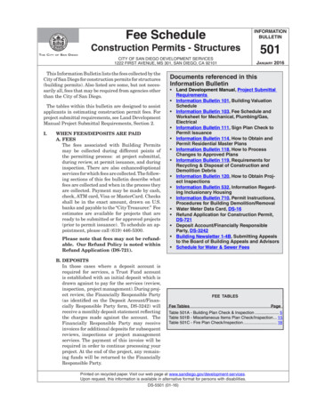
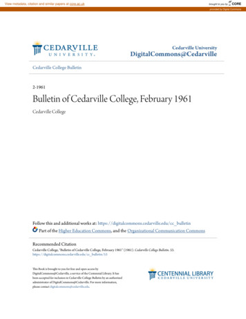
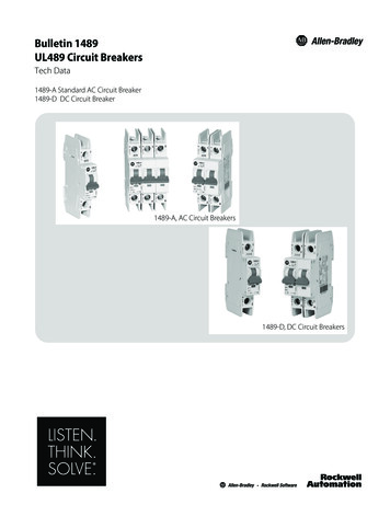
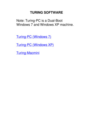
Bulletin 40-30 — Page 2it is then necessary to build a suitable filter box or frame atBulletin 30-34, Electric Duct HeatersExcept for Bulletin 30-05, a copy of each instruction isshipped with each piece of equipment. For air distributionsystem components there are many individual specificationswhich include installation instructions. Check for theinstruction upon unpacking the equipment.DISTRIBUTION SYSTEM AND ACCESSORIESThe key distribution system components are depicted onBulletin 20-15, System Component Specifications. The manyaccessory items shown on this specification sheet facilitateinstallation in a variety of situations.Any system installed where water leakage from condensateor a hot water coil MUST HAVE A SECONDARYDRAIN PAN installed. These are available as UPC-94 forthe M1218, UPC-20B and –20C for the M2430 modelswhen 2 or 3 modules are used and UPC-24B or –24C for theM3642 models for 2 or 3 modules or for the M4860 for 2modules. The UPC-24D is used for the M4860 for 3modules.Figure 1. Optional Air Handler Placementthe air handler.For basement or crawl space applications it can be handledas follows:1.2.3.Install a filter-grille low in the sidewall.Pan the basement or crawl space joists back to theair handler.Connect the flexible return air duct to the panning:A. By using the return air filter box normallysupplied and fasten it to panning.Where a vertical installation is planned the VerticalConversion Kits, UPC-63A for the M2430 and UPC-64Afor the M3642 and M4860, are required. The M1218 is amulti-purpose unit and does not require any kits ormodifications for vertical upflow applications.RETURN AIR COMPONENTSUnico, Inc. provides components for a complete return airsystem, including filters, which are particularly useful forattic type installations where one central ceiling return canbe used. Different components are required for each size ofair handler, which are detailed in Table 1.Table 1. Return Air Box ComponentsModelsReturn GrilleReturn Air DuctReturn *used to connect directly to the heating moduleThe return air duct, UPC-04-1218/2430/3642/4860, has asound attenuating core; flexible duct with a solid plasticlining which should not be used as it will be noisy.The standard return air components can be adapted to otherthan ceiling installation. The filter-grille can be installed inthe sidewall (see Figure 1). However, if a filter-grille cannot be used in the sidewall then other grilles can be used,such as a standard wall grille, a baseboard grille or an outof-the wall baseboard grille. The filter-grille is moredesirable because when other standard type grilles are used, Copyright 2007 Unico, Inc.Figure 2. Optional Grille PlacementB. Fabricate or obtain a sheet metal collar to whichflexible return duct can be fastened and connectto the panning. See Figure 2.When desired or necessary due to space limitations, afabricated return duct system can be used. This wouldusually be done when multiple return ducts are required.Fabricated duct board or metal duct with acoustical liningmay be used. The return duct including filter should bedesigned for a maximum static pressure drop of 0.15 IWC(37 Pa). A 90 bend or elbow should always be used forproper acoustical performance.Duct LayoutTo provide optimum system performance several importantguidelines must be followed in doing the duct layout. Thestatic pressure of the system determines the airflow for goodsystem performance. The system operates most effectively
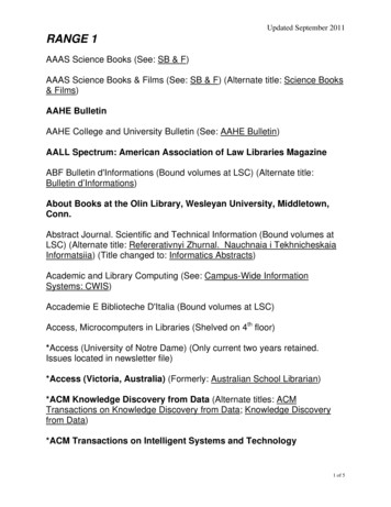
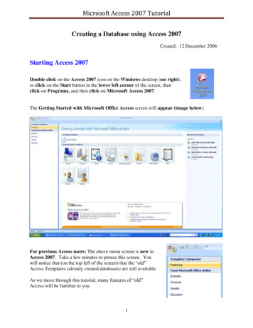
Bulletin 40-30 — Page 3it imposes a much higher-pressure drop. Suggestedlayouts using tees are shown in Figure 3. It is best toinstall the tee or elbow 48-inches from the unitalthough 24-inches is acceptable in tight places.in the range of 1.0 to 1.5 IWC of total static pressurereflecting both the return air system and the supply side ordistribution system.Plenum Layout4.Tee Airflow Splits: When using a tee, split the flowas close to 50/50 as possible—no more than 60/40.Use a turning vane for the M4860; it is notnecessary for the smaller models. For the M4860unit it is preferable to us 10-inch insulated roundsheet metal up to the tee, then a 10x9x9-inch tee(Unico Part No. UPC-19(V)-100909) providing 9inch branch runs in both directions. In this case a70/30 split in airflow is possible.5.Shotgun Systems: Where a shotgun system (seeFigure 3) provides a better layout for the M4860unit, use 10-inch insulated metal or fiberglass ductfor the first 40% of the airflow, then reduce to 9inch for the remaining 60%, if desired. For smallerunits, 9-inch may be run the entire length.6.Horseshoe / Perimeter Patterns: Where horseshoeor “H” systems are used, consider closing thehorseshoe or end of the “H” into a perimeter loop(see Figure 4).For the Unico System the installer has a choice of 2 differenttypes of plenum systems: square fiberglass duct board (61/2 x 6-1/2, 8-1/2 x 8-1/2, and 9-1/2 x 9-1/2-inches I.D.) andfield insulated round sheet metal (7, 9 and 10-inch I.D). Incertain cases with space limitations, such as droppedceilings, it is possible to use plenum that is flatter, such asrectangular fiberglass ductboard or sheet metal. In thesecases the dimensions should provide a flow area at leastequal to or greater than the factory supplied plenum, e.g. 4 x11-inch I.D. or 5 x 9-inch I.D.The following guidelines should be followed for the plenumsystem:1.2.3.More Plenum, Less 2-inch run length: Theplenum has less pressure drop than the 2-inch ductruns so the plenum system should be designed tokeep the 2-inch duct runs to a shorter length (12-ft.or less, if possible). This may require using moreplenum and plenum fittings and consideration oflayouts that are not always the most obvious.Minimize Restriction: The UNICO SYSTEM suppliedplenum fittings are designed to minimize restrictionof the plenum system. They include full flow teeswith turning vanes (where helpful) and full flowelbows. If locally supplied components, such assheet metal fittings, are to be used be sure they areof full flow design.First Fitting—Tee: Every effort should be made touse a tee as the first fitting off the air handler,particularly with the M4860. When an elbow is usedFigure 3. Typical System Layouts Copyright 2007 Unico, Inc.40% Min.9 inch60%7 inchShotgun SystemFigure 4. Typical Shotgun System Layout
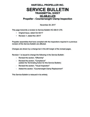
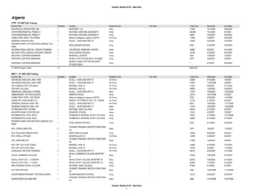
Bulletin 40-30 — Page 430%Max.Side Branch SystemFigure 6. Typical Side-Branch System Layout7.Side Branch: For a side branch, turn the tee 90 andnever use a turning vane. Take no more than 30% ofthe airflow from the side branch (see Figure 5).8.Minimum Distance to Fittings: Always use astraight duct prior to any fitting such as elbow, tee,plenum takeoff, or electric heater. It is best to have48 inches before each fitting although 24-inches isacceptable in most applications. Avoid elbowsFigure 7. Typical Plenum Horizontal LayoutREMEMBER THAT ANY TIME THE DISTRIBUTIONSYSTEM CAN BE LOCATED IN THE CONDITIONEDSPACE THERE IS NO DUCT LOSSES AND ENERGYWILL BE SAVED.OUTLETS AND SUPPLY DUCT LAYOUTThe following guidelines apply to the outlets and 2-inchduct runs:1.Minimize Length, Minimize Restriction: Keepthe 2-inch supply duct length as close to 12-feet aspossible and never less than 6-feet. Use the fewestnumber of bends as possible. Maximize the radius ofany bends making sure the bend in the soundattenuating tubing near the outlet is at least 6-inchesFigure 5. Typical Plenum VerticalLayoutdirectly off units, which is the worst design possible.9.Space Takeoffs Evenly: Maintain the distancebetween takeoffs as evenly as possible. Space thetakeoffs at least 6-inches apart and 12-inches fromthe end cap.6"10. Plenum for Multiple Stories: The plenum isnormally in the attic or basement. In some two storyor split-level home it is advantageous to go fromone level to another with the plenum. Boxing in theplenum (see Figure 6) or routing it through a closetusually accomplishes this.11. Plenum in Living Area: In some homes where atticspace is not available, the plenum can be enclosedby boxing it in (see Figure 7) or running it abovedropped ceilings. In areas with cathedral ceilings,this can be done along with boxing in the supplytubing next to an exposed beam. Remember thatonce the system is boxed in it is difficult to gainaccess for changes so it is imperative that the systembe properly designed and checked out for airflowbefore final boxing is done. Copyright 2007 Unico, Inc.Figure 8. Typical Supply Tubing Bend2.(see Figure 8).6 Outlets Per Ton Minimum: Provide aminimum of 6 full outlets per ton of cooling (200CFM/ton minimum). For the M4860 unit on a 5-tonsystem and any heat pump system use 6-1/2 fulloutlets per cooling ton. For hot water heating, use40 CFM per full outlet and refer to hot water coilperformance charts to get the required total. A fulloutlet is 10-feet of supply duct without anybalancing orifices. Add more outlets for those less
Bulletin 40-30 — Page 5than full. For example, two runs 10-feet long with50% balancing orifices are equal to one full outlet.3.10% Rule: For supply ducts longer than 10-feet,the air is reduced in that run by 10% for every 5-feetover 10-feet. The curves provided in Bulletin 40-40,System Sizing and Layout Procedure takes this intoaccount when doing the detailed layout for roomoutlet selection.4.Consider Traffic Pattern: Place outlets out ofFigure 11. Incorrect Placement of Tubingstud wall (usually 3-1/2-inches wide) for horizontaldischarge with the sound attenuating tubing in thewall with a 90 turn. This application is notacceptable because of the short radius in the tubing.The air noise would not be acceptable (see Figure11). For stud wall applications use the slotted outlet.7.Figure 9. Typical Kitchen Soffit LayoutFigure 10. Typical Cabinet Layouttraffic pattern. A corner, 5-inches from each wall, isa good location, or along walls or blowinghorizontally. Two excellent spots for horizontaldischarge are in the soffit above kitchen cabinets(see Figure 9) and in the top portion of closets (seeFigure 10). Consider floor outlets (with screens) forunits located in the basement.5.Allow for aspiration: Locate outlets so the airstream does not impinge on any objects or people –at least 3-feet away. Use outlet deflectors and outletbalancing orifices sparingly as they disrupt theaspiration.6.No Terminators in Stud Walls: Do not attemptto install the terminators in a standard 2 x 4-inch Copyright 2007 Unico, Inc.Proper Installation for Noise: In planning thelength of duct runs be sure to provide sufficientlength that gives as generous a radius as possible inthe sound attenuating tubing at the outlet. Minimumradius must be 6-inches as indicated but the greaterthe radius of any bend at the outlet the quieter therun will be. Be sure to include a minimum of 3-feetof sound attenuating tubing (UPC-26C) at the end ofeach run. For runs up to 12-feet all soundattenuating tubing may be used. For greater lengths,use the aluminum core supply tubing (UPC-25) witha 3-foot attenuator at the end.Also, adding a few extra outlets can reduce soundlevels further. The round outlet is designed for 20 to40 cfm. The slotted outlet is designed for 20 to 35cfm. As a general rule the more outlets, the lowerthe cfm per outlet and the lower the sound level willbe. For applications where all the surfaces (floor,wall, and ceiling) are hard it is best to design thenumber of outlets to achieve approximately 30 cfm.Also, sound is additive so that if you have a smallspace with lots of outlets it is best to design for 30cfm.Sound is subjective meaning what is acceptable forsome is not for others. Therefore, when in doubt adda few extra outlets. Rest assured, though, that thenoise level for any outlet within its allowable rangewill be quieter than most conventional duct systems,provided the outlets are properly installed.
Bulletin 40-30 — Page 6story. The first floor tubing is run from the plenumin the attic down through the second story to ceilingoutlets on the first floor (see Figure 13).SINGLE STORY APPLICATION LAYOUTThis application is normally the quickest and simplestapplication to make. Figure 12 is a typical layout for this typeof structure.The supply tubing is small enough to go in studspaces but this is often difficult in older homesbecause of hidden obstructions in the walls. It isFigure 15. Placement of Supply tubingusually easier to run the supply tubing from the atticdown through second story closets to first storytermination (see Figure 14).Figure 12. Typical System Placement and LayoutAnother common practice is to run supplytubing from the attic down into corners of thesecond story rooms to first story outlets. Supplytubing in the corners of the second story roomsTwo Story Application LayoutThe two-story residence is usually handled in one of twomanners:1.One UNICO SYSTEM in the attic with supply tubingrun in the attic to ceiling outlets for the secondFigure 13. Placement of Supply Tubingbetween FloorsFigure 14. Two-Story Home with One Unico System Copyright 2007 Unico, Inc.can then be boxed in and are hardly noticeablesince the overall diameter of tubing is only 31/2-inches (see Figure 15).
Bulletin 40-30 — Page 72.The second most common way to handle the oldertwo-story home is to install two separate systems.One is placed in the attic to handle the second storyFigure 16. Placement of Supply Tubing between Floorswith ceiling terminators and return air. The othersystem is placed in the basement utilizing floorterminators with the duct system suspended in thebasement area (see Figure 16).With two systems, it often takes less time on the job andgives the homeowner a truly zoned system where thecomfort conditions of the two areas can beindependently controlled.Split Level ApplicationsThe UNICO SYSTEM distribution system on cooling onlyinstallations where the duct system is in the nonconditioned areas, such as attics, should be blocked offduring the winter season. Winter shutoff caps areshipped with the installation kits. For the return air grillea sheet metal plate can be fabricated to fit in front of thefilter.If a residence has proper or more than adequate humidityduring the heating season, it is possible for this air totravel throughout the distribution system. When thisoccurs, moisture from the humidified air can condenseon the inside of the plenum and the supply tubing. Anexcess quantity of moisture collected in the distributionsystem may result in wet ducts and water dripping fromthe terminators.Be sure the Homeowner is given the winter shutoffcaps and return air grille block off and understandsthe importance of their use during the heatingseason. Copyright 2007 Unico, Inc.
Any system installed where water leakage from condensate or a hot water coil MUST HAVE A SECONDARY DRAIN PAN installed. These are available as UPC-94 for the M1218, UPC-20B and -20C for the M2430 models when 2 or 3 modules are used and UPC-24B or -24C for the M3642 models for 2 or 3 modules or for the M4860 for 2 modules.