Transcription
Performance Specificationfor Thermal StoresDirect integrated thermal storesIndirect integrated thermal storesHot water thermal storesBuffer stores
Performance Specificationfor Thermal Stores Direct integrated thermal stores Indirect integrated thermal stores Hot water thermal stores Buffer stores
This document specifies the performance requirementsand the test procedures for the primary (non-potablewater) thermal energy stores listed below:1.11.2Integrated thermal stores, which use thestored energy (i.e. the preheated primary hotwater) directly for space heating and indirectlyfor producing instantaneous domestic hot waterand which are suitable for:-Thermal stores with factory fitted electrical wiring mustalso comply with the current and relevant IEE and BS3456requirements. Individual dwellings. Thermal storage group heating schemes forblocks of flats.The construction of the thermal store and the fittingsand the components used or specified must also complywith the requirements of the ‘Model Water Bylaws’ andthe relevant British Standards.Hot water only thermal stores, that use storedenergy (i.e. the pre-heated primary hot water)indirectly for producing instantaneous domestichot water only and which are suitable for:-Where a thermal store is unvented i.e. intended fora sealed heating system application, it must complywith the Building Regulations Approved Document G3Hot Water Storage, 1992 Edition and relevant BritishStandards e.g. BS5449: 1990. Individual dwellings. Thermal storage group heating schemes forblocks of flats.At the time of publication, this document took accountof the standards, regulations, etc prevailing at the time.No responsibility can be taken for subsequent changesor product developments.Buffer stores, which supply preheated waterto integrated thermal stores in the individualapartments in thermal storage group heatingschemes for blocks of flats.SCOPE1.3It does not cover the materials and manufacturing of thethermal stores and the associated components but themanufacturer must comply with the requirements of BSEN ISO 9002 or must be in the process of applying forapproval.Page
1ScopeAppendices2DefinitionsATest rig and test procedures for evaluating theperformance of the hot water heat exchanger ofintegrated thermal stores (DITS and IDITS) and hotwater thermal stores (HWTS).General RequirementsBThermal store data badgeThermal store design and installation manualsFlow and return connectionThermostat pocketsLabelling of connectionsSize of connectionsDescaling of hot water heat exchangerTest rig and test procedures for evaluating theperformance of the primary heat exchanger ofan indirect integrated thermal stores (IDITS) andindirect buffer store (IDBS).CTest rig and test procedures for measuring thestandby heat loss of a thermal store and thetemperature of the water in the integral feed andexpansion tank.Performance SpecificationDDetails of the coded information for the thermalstore ‘data badge’.EPerformance and design information to beincluded in the design and installation manuals.Definition of terminologyDefinition of thermal stores34Domestic hot water performanceHot water performance without temperaturecontrol devicePerformance of a domestic hot water temperaturecontrol devicePressure loss through a domestic hot water heatexchangerPerformance of a primary heat exchangerHeat transfer capacity of a primary heatexchangerPressure loss through a primary heat exchangerStandby heat loss from a thermal storeHeat losses with pipe workHeat losses without pipe workHeat losses for SAP CalculationsTemperature of water in the integral feed andexpansion tank.5Specification of ComponentsCONTENTSStore thermostat pocketsExpansion vesselHot water temperature limiting devicePump over-run controlAnti vacuum and air release valves2-Port charge control (e.g. zone) valveMetering systemsPage
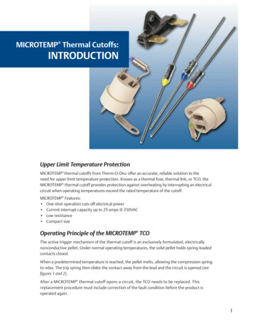
2.1DEFINITIONS OF TERMINOLOGY2.1.1 Capacity of a thermal storeNet volume of primary water in a thermal storeused for storing the primary heat energy fordomestic hot water and/or space heating.2.1.2 Store ThermostatOne or more thermostats used to control thetemperature of the primary water in the thermalstore by either controlling the operation ofthe boiler in an individual dwelling or a chargecontrol valve in a group heating scheme.2.1.8 Data badgeA badge fitted to the thermal store, which givesinformation about safety, identification andessential performance information in the codedform.2.1.9 Installation and design manualOne or more comprehensive sets of documentssupplied with every thermal store containingsystem design,installation and service informationfor that store.142.1.3 Primary heat exchangerA heat exchanger in an indirect thermal store,which transfers energy from a heat source e.g. aboiler to the primary water in the store.2.1.4 Natural convection hot water heat exchangerA water to water heat exchanger inside a thermalstore (figure 2.1) which transfers heat from theprimary water to the domestic hot water duringa hot water draw-off without using motive power(e.g. a pump) to circulate primary water.532Figure 2.1: Natural convectionhot water heater exchanger12.1.5 Forced convection hot water heat exchangerA water to water heat exchanger inside (figure2.2) or outside a thermal store (figure 2.3) whichrequires a motive power (e.g. a pump) to circulatethe primary water through the heat exchangerduring a hot water draw-off.The pump used for circulating the primary waterthrough the heat exchanger during the hot waterdraw-off may also act as a boiler and/or a heatingcircuit pump.62435Figure 2.2: Forced convectionexternal hot water heat exchanger6DEFINITIONS2.1.6 Domestic hot water temperature controllerA device (e.g. a thermostatic non electricblending valve) which is fitted to thermal storefor regulating the domestic hot water outlettemperature and which also limits the ‘hot slug’of water reaching the outlets.2.1.7 Hot slugThe volume of hot water above 60 C passedduring a domestic hot water draw-off when thetemperature-regulating device is set to controlthe outlet temperature at 55 C.Page 45321Figure 2.3: Forced convectioninternal hot water heat exchanger123456Thermal storePrimary waterMains cold water inletHot water to tapsHot water heat exchangerPrimary pump
2.2DEFINITIONS OF THERMAL STORES(c)2.2.1 Integrated thermal store (ITS)(a)(b)A thermal store designed to store primary hotwater, which can be used directly for spaceheating and indirectly for domestic hot water.In a group, heating scheme the primary waterin DITS is heated by one or more boilers or issupplied with pre-heated water from one or morebuffer stores.2.2.3 Indirect integrated thermal store (IDITS)(a)An integrated thermal store (ITS) which complieswith the requirements of section 2.2.1. and inwhich the primary water is heated indirectly bymeans of an internal primary heat exchanger(figure 2.5).(b)The indirect integrated thermal store (IDITS) isnormally used in a thermal storage group heatingscheme and is heated by the central boilers.In an integrated thermal store (ITS) the heatingprimary water is circulated to the space heatinge.g. radiators. Therefore, the minimum storagevolume given by equation 1 must be available forspace heating.VH 45 0.25VS ----- (1)Where:-2.2.4 Domestic hot water thermal store (HWTS)(c)In an Integrated thermal store (ITS), thedomestic hot water is heated instantaneouslyby transferring the heat from the primary storedwater to the domestic hot water flowing throughthe heat exchanger. The domestic hot water heatexchanger may be:-(a)A thermal store designed to provide domestichot water only and is heated directly or indirectlyby a heat source e.g. a gas boiler. Typical directand indirect domestic hot water thermal stores(HWTS) are shown schematically in figures 2.6and 2.7 respectively.(b)In a hot water thermal store (HWTS), thedomestic hot water is heated instantaneouslyby transferring the heat from the primary storedwater to the domestic hot water flowing throughthe heat exchanger. The domestic hot water heatexchanger may be:- An internal natural convection type shownschematically in figure 2.1. An external forced convection type shownschematically in figure 2.2. An internal forced convection type shownschematically in figure 2.3.(d) An internal natural convection type shownschematically in figure 2.1. An internal forced convection type shownschematically in figure 2.2. An external forced convection type shownschematically in figure 2.3.The ITS acts as a buffer between the heat energysource (e.g. boiler) and the ever changing spaceheating and hot water energy demands of adwelling.(c)Both direct and indirect HWTS are suitable forindividual dwellings.(d)Indirect HWTS are also suitable for group heatingand district heating schemes.2.2.2 Direct integrated thermal store (DITS)(a)An integrated thermal store (ITS) which complieswith the requirements of section 2.2.1 and inwhich the primary stored water is heated directlyby an internal or an external heat source.(b)In an individual dwelling, the primary water inDITS is heated by dedicated heat source e.g. a gasboiler as shown in figure 2.4.Page DEFINITIONSVH Minimum storage volume available forspace heating (l)VS Storage capacity of the thermal store (l)
1V1371V14V26V21093Figure 2.4: Direct integrated thermalstore (DITS) with natural convectionhot water heat exchanger andthermostatic mixing valve for regulatingthe hot water outlet temperature13589Figure 2.5: Indirect integrated thermalstore (IDITS) with external forcedconvection hot water heat exchangerand electronic controls for regulatingthe hot water outlet temperature143511102456109693Figure 2.6: Direct hot water only thermalstore (HWTS) with natural convectionhot water heat exchanger andthermostatic mixing valve for regulatingthe hot water outlet 012Figure 2.7: Indirect hot water only thermalstore (HWTS) with forced convection hotwater heat exchanger and boiler fittedwith sealed system kitThermal store2 Hot water heat exchangerHot water outlet5 Mains cold water inletThermostatic mixing valve 8 Space heating pumpBoiler11 Diverter valveThermal store volume NOT available for space heatingThermal store volume available for space heatingPage 36912Primary waterBoiler/system pumpSpace heating circuitSealed system kit
2.2.5 Direct buffer store (DBS)2.2.6 Indirect buffer store (IDBS)(a)A thermal store heated directly by one or moreboilers in a group-heating scheme (1) shownschematically in figure 2.8. In these heatingsystems, the DBS is used for supplying primaryhot water to direct integrated thermal store(DITS) located in the individual dwellings.(a)A thermal store heated indirectly by one ormore boilers by means of an internal primaryheat exchanger and is used in a group heatingscheme (figure 2.8) for supplying hot water todirect integrated thermal stores (DITS) located inindividual dwellings.(b)The buffer store thermostats control the operationof one or more boilers in a thermal storage groupheating scheme.(b)The buffer store thermostats control the operationof one or more boilers in a thermal storage groupheating scheme.(c)A direct buffer store does not have a built in heatexchanger for supplying domestic hot water.(c)An indirect buffer store cannot have a built in heatexchanger for supplying domestic hot water.Note:(i) The details of the thermal storage groupheating systems are contained in a separatepublication.11861 Indirect integrated thermalstores in individual dwellings2 Direct buffer store (DBS)3 Indirect buffer store (IDBS)4 Boiler5 Boiler pump6 Buffer store charge control valve7 IDBS primary heat exchanger8 Distribution pump2113647455Figure 2.8: Schematic diagram of a thermal storage group heating schemePage DEFINITIONS8
2.2.7 Integrated thermal stores (DITS & IDITS) forindividual dwellings(a)A typical integrated thermal store (ITS) heatingsystem for an individual dwelling is shown infigure 2.9. The design of an ITS for individualdwellings must ensure that: One or more store thermostats control theoperation of the boiler and the boiler pump.(b)Both direct and indirect integrated thermalstores (DITS and IDITS) having either a natural ora forced convection hot water heat exchangersare suitable for individual dwellings.(c)Thermal stores designed for an open system andfor individual dwellings may have an integral orremote feed and expansion tank.(d)Thermal stores designed for sealed heating(i.e. closed) system and for individual dwellingsmust be fitted with safety devices and controlsspecified in the Building Regulations ApprovedDocument G3. The user space heating controls e.g. a roomthermostat, heating programmer, must controlthe operation of the space heating pump andnot the operation of the heat generator. It meets the requirements of sections 3 and 4.Figure 2.9: Typical integrated thermal store (DITS) based heating system for individual 131517Hot water outlet to tapsExpansion Vessel (1)Heating programmerThermostatic mixing valveBoiler pumpBoiler circuit check valve (2)Integrated feed and expansion cisternBoiler pump over-run timerHot water heat exchanger check valve16246810121416Mains cold water inletSpace heating pumpRoom thermostatHeating circuit check valve (2)BoilerStore thermostat/sensorWiring centreMains supply 1 x 230V ac, 50HzNotes(1) Expansion vessel can be integral part of the hot water heat exchanger(2) To be fitted on site if requiredPage
2.2.8 Hot water thermal stores for individualdwellings It meets the requirements of sections 3 and 4.(b)(a)Both direct and indirect HWTS designed forindividual dwelling may have an integral orremote feed and expansion tank or may befitted with sealed system components, whichmust comply with Building Regulations andappropriate British Standards.Typical heating systems based on direct andindirect hot water only thermal stores (HWTS)are shown in figures 2.10 and 2.11 respectively.The design of HWTS for individual dwelling mustensure that:-Note: If the hot water has priority then the storethermostat controls the operation of the boiler,system pump and the 3-port diverter valve.(i) In a heating system incorporating an HWTS,if the domestic hot water has a priority thenif space heating is ON and the thermal storecontrol thermostat(s) calls for heat, the spaceheating is switched OFF until the thermalstore is satisfied. If a flow share arrangement is used thenthe user space heating controls e.g. a roomthermostat, heating programmer, shouldcontrol the operation of the boiler, systempump and the position of the 3-port divertervalve together with store thermostat.(ii) Compared to an integrated thermal store,an HWTS system increases the boiler cyclingwhen the space heating is ON.13717965132812410141516Figure 2.10: Typical direct hot water thermal store (HWTS) based heatingsystem for individual 12184151416Figure 2.11: Typical indirect hot water thermal store (IHWTS) based heatingsystem for individual dwellingsPage Hot water outlet to tapsMains cold water inletExpansion Vessel (1)Bypass valveHeating programmerRoom thermostatThermostatic mixing valve3-Port valveBoiler/system pumpBoilerAir vent and anti-vacuumvalveStore thermostat/sensorIntegrated feed andexpansion cisternWiring centreBoiler pump over-run timerMains supply 1 x 230V ac, 50HzHot water heat exchangercheck valveSealed system kitDEFINITIONS11
2.2.9 Integrated thermal stores for group heating(a)(b)Both direct and indirect integrated thermalstores (DITS and IDITS) with natural or forcedconvection hot water heat exchangers aresuitable for thermal storage group heatingsystems. Typical configurations of DITS and IDITSfor this application are shown in figures 2.12 and2.13 respectively.(c)A thermal store for group heating system isnormally fitted with a metering system forapportioning the running costs.(d)A direct integrated thermal store (DITS) for agroup-heating scheme can not have an integralor remote feed and expansion tank.(e)An indirect integrated thermal store (IDITS) fora group-heating scheme must have an integralor remote feed and expansion tank or must besuitable for a sealed system and be fitted withappropriate system components.(f )Integrated thermal stores (DITS and IDITS) mustcomply with the requirements of sections 3 and 4.A thermal store for group heating system doesnot directly control the operation of the boilersbut the store thermostat(s) control the operationof the charge control re 2.12: Typical direct integrated thermal store (DITS) based heating system foran apartment in a group heating scheme1 Isolating valve2 In line filter3 Balancing valve4 Heat meter5 Store charge control valve166 Distribution network7 Store thermostat8 Space heating pump159 Cold water inlet10 Hot water outlet to taps10611 Hot water heat exchanger1112 Space heating circuit913 Wiring and controls7514 Mains electricity supply1 23230V ac, 50 Hz15 HW heat exchanger pump1816 F & E cistern17 Air vent / anti-vacuum valve18 Programmer19 Room thermostat4Figure 2.13: Typical indirect integrated thermal store (IDITS) based heating system foran apartment in a group heating schemePage 10
2.2.10 Hot water only thermal stores (HWTS) forgroup heating(b)Only indirect hot water only thermal stores aresuitable for group or district heating systems.Typical configuration for the application is shownin figure 2.14.A HWTS for group heating scheme may be fittedwith a metering system for apportioning therunning costs.(d)Hot water thermal store must comply with therequirements of sections 3 and 4.A hot water thermal store does not control theoperation of the central boilers directly but thestore thermostat(s) control the operation of thecharge control valve.Figure 2.14: Typical indirect hot water only thermal store (HTS) based heating systemfor an apartment in a group heating lating valveBalancing valveStore charge control 3-port valveStore thermostatHot water outlet to tapsSpace heating circuitMains electricity supply 230V ac, 50HzF & E cisternRoom thermostat24681012141613In line filterHeat meterDistribution networkCold water inletHot water heat exchangerWiring centre and controlsHW heat exchanger pumpProgrammerDEFINITIONS(a)(c)Page 11
3.1THERMAL STORE DATA BADGE3.2The following minimum information shall beprovided in the form of a Data Badge fixed tothe thermal store. The badge must be accessiblewithout the use of tools.THERMAL STORE SYSTEM DESIGN ANDINSTALLATION MANUALThese manuals should be provided with allthermal stores and should include (whereappropriate) the following information:- Section 3.1.1 applies to all types of thermalstores i.e. DITS, IDITS, HWTS, DBS and IDBS.(a)Performance and design information as definedin appendix E of this document. Section 3.1.2 applies to direct and indirectintegrated thermal stores (DITS and IDTS) andboth direct and indirect hot water thermalstores (HWTS).(b)Installationexamples.(c)Recommended space heating system designsand control.(d)Recommended hot and cold water distributionnetworks in a dwelling (e.g. supply to shower andpipe sizes).3.1.1 For all types of thermal stores3.3FLOW AND RETURN CONNECTIONS(a)(b)(a)These should be designed to prevent short circuitof flow and return in the store for both the boilercircuit and the space heating circuit.(b)The aim should be to achieve uniform flow (upor down) across the diameter of the store. Thiscan be achieved by using sparge pipes, diffusersor other similar methods.3.4THERMOSTAT POCKETS(a)The thermostat pocket should be designed andlocated to sense the bulk water temperature inthe active zone of the store.(b)Thermal stores of capacity up to 210 litres shouldbe fitted with ONE store thermostat pocket andthermal stores of capacity greater than 210 litresshould be fitted with TWO thermostat pockets asshown in figure 3.1.(c)The position of the store thermostat pocketsmust comply with equation 2 or 3a and 3b. Section 3.1.3 applies to indirect integratedthermal stores (IDITS), indirect hot waterthermal stores and indirect buffer stores(IDBS).(c)(d)(e)(f )(g)Manufacturers name and address etc. [ .]Complies with Performance Specification forThermal Stores [ .]The model and identity number [ ]Primary water storage capacity (l)Maximum working head for the store [bar]Maximum working temperature (if specialcomponents fitted) [ C]Store thermostat settings [ C]andserviceinstructionswithGENERAL REQUIREMENTS3.1.2 Additional data for integrated thermal stores(a)(b)Maximum working pressure for hot water heatexchanger [bar]Code-A (Coded information as defined inappendix D)3.1.3 Additional data for indirect stores(a)(b)Maximum working pressure for primary heatexchanger [bar]Code B (Coded information as defined in appendixD)For VS 210l; 0.25 VS VB 0.35VS . (2)For VS 210l; 0.05 VS VB 0.10VS . (3a)0.60 VS VT 0.70VS . (3b)Page 12
Where:-3.5LABELLING OF CONNECTIONSVS Nominal storage capacity of a thermal store (l)VB Volume of water below store thermostat 1 (l)VT Volume of water below store thermostat 2 (l)(a)The thermal store should have clearly labelledconnections where applicable for: Figure 3.1: Position of store temperature controlthermostats or sensorsVS 210 litres210 litresVS VT 0.70VSVT 0.60VSVT1VBVB 0.35VSVB 0.25VS1VB 0.10VSVB 0.05VSVB1 Lower store thermostat2 Top store thermostat3.6SIZE AND TYPE OF CONNECTIONS(a)The pipe connections should be designed tominimise the heat losses from the thermal store.(b)The size of connections will depend upon thecapacity and the type of store. Normally 22mm forstores up to 140 litres, 28mm for stores up to 210litres, 35mm for stores up to 350 litres and 42mmfor stores up to 500 litres will be adequate.3.7DESCALING OF HOT WATER HEAT EXCHANGERVS Volume of the thermal storeVB Volume of water below store thermostat 1VT Volume of water below store thermostat 1(d)The two store thermostats should be wired asshown in figure 3.2 so that the boiler only fireswhen both thermostats are calling for heatand continue to fire until both thermostats aresatisfied. (Note: The same control action shouldbe achieved by electronic logic if non-mechanicalthermostats are used.)A means of descaling the hot water heatexchanger in the field must be provided and theprocedure must be outlined in the design andinstallation manuals.NL3LSL654114Bottom thermostatPump over run timer225Top thermostatBoiler pump362-Pole CO relayBoilerFigure 3.2: Schematic wiring diagram for twin thermostat control of thermal storesPage 13GENERAL REQUIREMENTS2Boiler or system flowBoiler or system returnHeating circuit flowHeating circuit returnMains cold water inletDomestic hot water outletCold feed and open ventAutomatic air vent and anti-vacuum valvePictorial labelling of components is acceptableprovided it is securely fixed to the thermalstore.
4.1DOMESTIC HOT WATER PERFORMANCETable 2 : Minimum average temperature rise of hot waterdraw-off4.1.1 General requirements(a)The requirements of sections 4.1.2., 4.1.3 and 4.1.4apply to both the direct and indirect integratedthermal stores and the hot water thermal stores(DITS, IDITS and HWTS) having forced or naturalconvection heat exchangers defined in section 2of this document.(b)(c)Test schedule (Appendix 1)Minimum averagetemperature rise of a draw-offA1: No heating load45 CA2: Design heating load40 C4.1.3 Hot water performance without hot watertemperature control deviceFor both individual dwellings and group heatingapplications, the hot water flow rate and volumeare related to the type of dwelling for which athermal store is designed.The hot water performance of a thermalstore should be measured using a test rig andtest procedures set out in appendix A of thisdocument. The flow rates and draw-off volumeslisted in table 1 should be used for these tests.The effectiveness of a thermostatic mixing valveor a similar device in preventing a hot slug ofwater reaching an outlet should be measuredusing the test procedure A3 in appendix A.(a)The maximum peak temperature and the volumeof the hot slug (see section 2.1.7) shall not bemore than the values specified in table 3.(b)The hot water performance of the thermalstore with and without a mixing valve or othertemperature regulating device (set at 55 C)should be presented as shown in figure A2 in theinstallation and design manual of that store.PERFORMANCE SPECIFICATIONTable 1 : Hot water draw-off volumes and flow ratesThermalstoreclassificationType ofthermal storeDraw-offvolume (l)Draw-offflow rate(l/s)*SC1:DwellingsFor showersonly400.13SC2:DwellingsFor 1bathroom670.30SC3:DwellingsFor 2bathrooms133Table 3: Maximum peak temperature and volume of hot slugof water at draw-off point.0.50* Normal flow rate (QN)4.1.2 Hot water performance without hot watertemperature control deviceThe domestic hot water performance of a thermalstore should be measured without a thermostaticmixing valve or a similar temperature regulatingdevice using the procedures and tests A1 and A2set out in appendix 1 of this document.(a)(b)The average temperature rise of the hot waterdraw-off of a specified volume and the specifiedflow rate must not be less than 45 C and 40 C fortests A1 and A2 respectively (see table 2).The temperature rise of the hot water from athermal store at the end of a draw-off must notbe less than 35 C in the tests A1 and A2.Flow rate (l/s)Maximum peaktemperature ( C)Maximum volumeof hot slug (l)0.1650.150.2650.200.3650.250.5650.304.1.4 Pressure loss of hot water heat exchanger(a)The pressure loss measurements of the domestichot water heat exchanger (internal or external)should be carried out using the test procedureA4, defied in appendix A.(b)The pressure loss at nominal water flow rategiven in table 1, should be declared on the storedata badge in the coded form.(c)Full pressure flow characteristics of the hot waterheat exchanger should be presented in thedesign manual in the format shown in figure A3.Page 14
4.2PERFORMANCE OF PRIMARY HEAT EXCHANGER4.3STANDBY HEAT LOSS FROM A THERMAL STOREAND ENERGY RATING4.2.1 General4.3.1 General(b)The requirements of this section apply to both theindirect integrated thermal store (IDITS) and theindirect buffer store (DBS) as defined in section 2.The test rig and the test procedure for measuringthe performance of the primary heat exchangerof indirect stores are defined in appendix B.(a)This section applies to all types of thermal storesincluding buffer stores.(b)The 24-hour average heat loss rate QHL, measuredusing the test rig (figure C1) and the procedureC2 and C3 given in appendix C, shall not begreater than the value, QHL-MAX, given by equation4. Alternatively, the maximum permitted heat lossrate, QHL-MAX, can be read from figure 4.4.2.2 Heat transfer capacity of primary heatexchanger(a)(b)QHL-MAX 1.6 x [0.2 (0.051 x (VS)2/3] ---- (4)The UA value i.e. the heat transfer capacity of theprimary heat exchanger shall be determined usingthe test procedure B1 outlined in appendix B.The nominal flow rate (QN) and the UA value foran average temperature difference of 6 C shall bedeclared on the store ‘data badge’ in the codedform.The complete design data as shown in figure B2shall be presented in the design manual.4.2.3 Pressure loss of primary heat exchanger(a)The hydraulic characteristics of the primary heatexchanger should be measured using the testprocedure, B2 outlined in appendix B.(b)The nominal flow rate (QN) and the pressure lossat the nominal flow rate shall be declared on thestore ‘data badge’ in the coded form.Where:QHL-MAX Maximum permitted heat loss from athermal store [kWh/24h]VS Declared capacity of thermal store (l)Note:(i)This figure should be regarded as an absolutemaximum and efforts should be made to reduceit.(ii)The actual measured value shall be declared onthe data badge in the coded form and also in theappliance manuals etc.The full design information in form shown infigure B3, shall be presented in the system designmanual for the store.Page 15PERFORMANCE SPECIFICATION(a)
Figure 4 : Maximum permitted heat loss from a thermal store6.0Heat loss rate nal volume (litres)PERFORMANCE SPECIFICATION4.3.2for SAP calculations4.3.2Heat Heatloss forlossSAP calculations(a)(a)(b)(b)(c)(d)(c)(d)Therefore its 24h average heat loss is lower thanITS.The heatIn-UseheatlossesThe In-Uselosses fromthermalstoresfromwill be thermal stores will be less than themeasuredvalues(seeThisless thanthe measuredvalues(see4.3.1.4.3.1. Thisis is because:The heat loss factors for Hot Water Only andbecause:Integrated Thermal Stores (HWS and ITS) forThe thermal stores are normally installedairingcupboardsause ininSAPproceduresmust belikecalculatedTheconventionalthermal stores arecylinder.normally installedin airing the ambientTherefore,temperaturewillbehigherusing appropriate equations as detailed in cylinder.for thetest proceduresand loosethereforethe heatthan 20separatesheet containedat thelossesback of thisthe ambientwill be higher than 20 Cwill be temperaturelower.document.specified for the test procedures and thereforethe Theheat losseswill be storagelower.thermalsystems are now being installed with two channel4.4 heatingWATER TEMPERATUREIN ANINTEGRATEDprogrammers for controlling both spaceand hot e nowbeingFEED ANDmaximumEXPANSION temperatureTANKthermalis notmaintainedat nominalofinstalledtwo channelprogrammersthe boileris not forcharging the thermal store, it will provide75 o C.withWhencontrollingbothofspacehot water.in 4.4.1This sectionapplies into allstores fitted40-50%hot heatingwater anddemandsa dwellingresultinga thermalsignificantlyTherefore,thethermal
(b) In a hot water thermal store (HWTS), the domestic hot water is heated instantaneously by transferring the heat from the primary stored water to the domestic hot water flowing through the heat exchanger. The domestic hot water heat exchanger may be:- An internal natural convection type shown schematically in figure .1.