Transcription
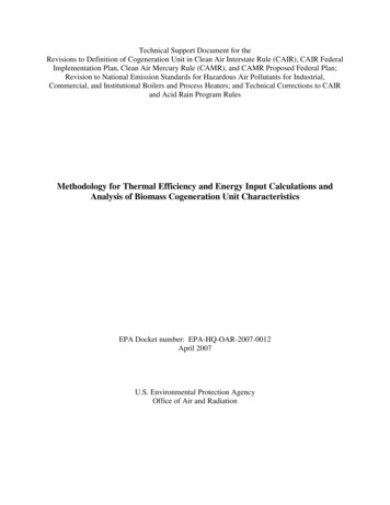
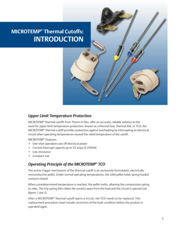
MICROTEMP Thermal Cutoffs:INTRODUCTIONUpper Limit Temperature ProtectionMICROTEMP thermal cutoffs from Therm-O-Disc offer an accurate, reliable solution to theneed for upper limit temperature protection. Known as a thermal fuse, thermal link, or TCO, theMICROTEMP thermal cutoff provides protection against overheating by interrupting an electricalcircuit when operating temperatures exceed the rated temperature of the cutoff.MICROTEMP Features: One-shot operation cuts off electrical power Current interrupt capacity up to 25 amps @ 250VAC Low resistance Compact sizeOperating Principle of the MICROTEMP TCOThe active trigger mechanism of the thermal cutoff is an exclusively formulated, electricallynonconductive pellet. Under normal operating temperatures, the solid pellet holds spring-loadedcontacts closed.When a predetermined temperature is reached, the pellet melts, allowing the compression springto relax. The trip spring then slides the contact away from the lead and the circuit is opened (seefigures 1 and 2).After a MICROTEMP thermal cutoff opens a circuit, the TCO needs to be replaced. Thisreplacement procedure must include correction of the fault condition before the product isoperated again.1
MICROTEMP G4, G6 & G7 Series TCOBefore OperationAfter OperationCASE AND LEADASSEMBLYCASE AND CSCOMPRESSIONSPRINGSTAR CONTACTTRIP SPRINGSTAR CONTACTTRIP YSEALISOLATEDLEADEPOXYSEALGrey area showscurrent pathGrey area shows opened orbroken current pathFigure 1MICROTEMP G5 & G8 Series TCOAfter OperationBefore OperationCASE AND LEADASSEMBLYTHERMALPELLETCOMPRESSIONSPRINGCASE AND LEADASSEMBLYDISCSSTAR CONTACTSTAR CONTACTTRIP SPRINGTRIP CERAMICBUSHINGISOLATED LEADISOLATED LEADEPOXYSEALEPOXYSEALGrey area shows opened orbroken current pathGrey area showscurrent pathFigure 22DISCSCOMPRESSIONSPRING
MICROTEMP Thermal Cutoffs:TYPES & SPECIFICATIONSMICROTEMP thermal cutoffs are available in a range of temperatures and electrical ratings to meetapplication requirements (see Microtemp Operating Temperature Summary and Electrical RatingSummary on page 4). There are 5 primary types of thermal cutoffs available. Standard dimensionsof each TCO series are shown on page 4.G Series: This “Global” series or G designation represents the world standard in thermal cutoffs.MICROTEMP TCOs were the first chemical-pellet spring-type TCO ever developed and continue to bethe thermal cutoff of choice for over 35 years.E Series: This new “Environmentally” friendly series holds Agency recognition equivalent to the Gseries and has been designed to comply with the Restriction of Hazardous Substances in Electricaland Electronic Equipment (ROHS) Directive (2002/95/EC). None of the substances specified in thisDirective have been intentionally incorporated into the E-series products.G4 SeriesRated for continuous operating currents up to 10 amps @ 250VAC (15 amps @ 120VAC, 5 amps @24VDC), the G4 series MICROTEMP TCO is the industry standard for over-temperature protection.The G4 series is applied to millions of appliances and personal care products each year, providingreliable back-up protection for temperature controlling thermostats and other over-temperatureconditions. The G4 series is also widely applied in office machines, portable heaters and industrialequipment as a thermal safeguard.G5 SeriesDesigned for higher voltage and current applications than the G4, the G5 series MICROTEMP TCO is rated for operating currents up to 20 amps @ 250VAC and 277 VAC (25 amps @ 120VAC).Similar in appearance to the G4 series, the G5 series has a different internal construction designedfor interrupting higher currents and withstanding higher temperatures.G6 SeriesThe G6 series MICROTEMP TCO can be utilized in applications where a higher maximum-overshoottemperature rating is not required, yet it is rated for operating currents up to 16 amps @ 250VAC. Itis the same physical size as the G4, G5 and G8 series TCOs.G7 SeriesThe G7 series MICROTEMP TCO is designed to satisfy applications requiring miniaturized componentsthat do not need maximum current interrupt capability. The G7 is just 2/3 the size of the G4 and G5,and with a current interrupting capability of 5 amps @ 250VAC (5 amps @ 24VDC), it is capable ofmeeting the requirements of transformers, motors, battery packs and electronic circuit applications.G8 SeriesDesigned for very high-current applications such as major appliances and high-wattage electric heatpackages, the G8 series MICROTEMP TCO is rated for operating currents up to 25 amps @ 250VAC(20 amps @ 277VAC). More economical than electromechanical bimetal-type one shot devices, it canbe utilized in applications where its small size is an advantage in terms of mounting (it’s the samephysical size as the G4, G5 and G6 series TCOs) and thermal response.3
MICROTEMP TCO Operating Temperature SummaryHoldingTemperature COpenTempTh CTh CTf C G4, G5, G7 G6, 77167205——216200191229200200240200200Maximum Overshoot Temperature CTm 75375450Tm 75375375Tm ��375450Tm ��——Tm CTm CTm CG8R9 Series R7 375375—Tm – Maximum overshoot temperature:temperature up to which TCO willnot change statusTf – Functioning open temperaturetolerance: 0, -5 CTh – Maximum temperature of theMICROTEMP TCO measured at thecase end of the thermal cutoff atwhich the thermal cutoff can bemaintained for a period for 168hours without opening.NOTE: it is advised that TCOs are notexposed to continuous operatingtemperatures in excess of Tf -25 C.C.T.I. – Comparative tracking index(all primary thermal cutoffs):250VACNOTE: G4, G5, G6 ,G7 and G8 series TCOswith TF 175 C comply with ULconductive heat aging (CHAT)requirements.Electrical Rating SummaryElectrical Current & Voltage RatingAgencyUL/CSAVDEG4 SeriesResistiveInductiveG5 SeriesResistiveG6 SeriesResistive10A/250VAC 8A/250VAC 20A/250VAC16A/250VAC15A/120VAC 14A/120VAC 25A/120VAC5A/24VDC21A/240VAC20A/277VAC10A/250VAC 8A/250VAC20A/250VAC 16A/250VAC15A/120VAC 14A/120VAC5A/24VDCMETI10A/250VAC—15A/250VAC 15A/250VACCCC10A/250VAC—16A/250VAC—G7 SeriesResistiveInductiveR9 SeriesResistiveR7 SeriesResistive5A/250VAC 4.5A/250VAC25A/250VAC5A/24VDC 4.5A/120VAC——5A/250VAC 4.5A/250VAC25A/250VAC5A/24VDC 4.5A/120VAC——5A/250VAC5A/24VDC5A/250VACG8 SeriesResistive——15A/250VAC———MICROTEMP TCOStandard DimensionsDimensions – Inches (millimeters)4G4, G5, G6 & G8 SeriesG7 SeriesStandardLeadsA Overall Length .12 ( 3.0)B Case Lead Length .06 ( 1.5)2.51 (63.8)1.38 (34.9)N/AN/ALongLeadsA Overall Length .12 ( 3.0)B Case Lead Length .06 ( 1.5)3.26 (82.9)1.38 (34.9)3.26 (82.9)1.38 (34.9)0.040 (1.0)Tin-Plated Copper0.040 (1.0)Silver-Plated Copper0.023 (.57)Tin-Plated Copper0.023 (.57)Silver-Plated Copper0.58 (14.7)0.158 (4.0)0.38 (9.6)0.118 (3.0)Lead Materialand DiameterCCDDCase Lead DiameterCase Lead MaterialEpoxy Lead DiameterEpoxy Lead MaterialCaseDimensionsEFCase Length (Reference)Case Diameter (Reference)7A/250VAC7A/24VDC—
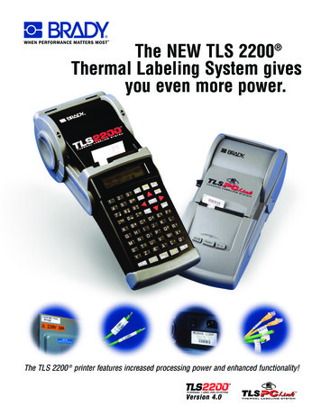
Packaged Thermal CutoffsTherm-O-Disc also offers a variety of packaging options for MICROTEMP thermal cutoffs.Therm-O-Disc offers two standard packages with wide application in the HVAC industry. Primarilydesigned for heating applications, the GXAM04 and GXAM06 packages mount a standard G4, G5,G6 or G8 TCO in a high temperature ceramic base (see figure 3).The popular GXAP Potted TCO packages consist of a TCO epoxy-potted into a plastic insulatingmounting case. The assembly can be supplied with various case materials, shapes and terminations.They can be used to accurately sense temperature as probes and as surface, airstream and ambientsensors (see figure 4). They can be easily replaced in the field without disturbing the rest of the circuit.Custom packages, insulations or special assemblies may be specified to meet specific uniqueapplication needs. By taking advantage of our technical expertise and high volume productionmethods and equipment, we can provide significant savings on custom packages.Packaged TCO Material SpecificationsTypeBase MaterialMaterial RatingTemperature CMaximum TCOTemperature CGXAP01PBT Glass Filled120134GXAP02PPS Glass Filled220192GXAP04PBT Glass Filled120134GXAP05PBT Glass Filled120134GXAP10PPS Mineral Filled220192GXAP12PBT Glass Filled120134GXAM04Ceramic DIN VDE 0335, C 221 250260GXAM06Ceramic DIN VDE 0335, C 221 250260GXAM11PBT120134*Additional ratings available upon request.GXAM06GXAP02GXAP04GXAM11GXAM04Figure 3GXAP12GXAP05Figure 45
Lead ConfigurationsThe MICROTEMP TCO can be furnished with virtually any lead configuration specified for anapplication. Lead curls are available to match most sizes of screws along with varying lead lengthsand lead forms.All types of terminations, such as quick connects, ring terminals and blade terminals, are availableat additional cost. In addition, tape and reel packaging can be specified to meet high volumerequirements.Temperature RatingsMICROTEMP thermal cutoffs are available in a wide range of opening temperatures, providingdesigners a high degree of flexibility (see Microtemp TCO Operating Temperature Summary atthe top of page 4). Determining the correct TCO temperature calibration requires significantapplication testing.The proper calibration will be affected by application variables such as I2R self heating of theTCO, heat transfer through insulation and heat dissipation due to heat sinking and air flow.Thermocoupled TCO Test Samples (TTTS), that match the physical and electrical characteristicsof a functional TCO, are available to help evaluate application specific variables.For more information on testing and installing MICROTEMP TCOs, please review theMICROTEMP Thermal Cutoff Application Notes section.Direct Current (DC) ApplicationsThe G4 and G7 series MICROTEMP thermal cutoffs have published electrical ratings for directcurrent (DC) applications. Current interruption capacity in DC circuits is highly application sensitive.Therm-O-Disc recommends thorough testing of DC electrical applications using the testingguidelines in Therm-O-Disc’s MICROTEMP thermal cutoff technical information section.Samples and QuotationsMICROTEMP TCO samples and Thermocoupled TCO Test Samples (TTTS) are readilyavailable for determining the correct response and desired performance in an application.For more information on MICROTEMP TCOs, call a Therm-O-Disc sales engineer at 419-525-8300.6
Lead CuttingMinimum DimensionsDIM. AInches (millimeters)DIM. CDimension ADimension BDimension C0.95 (24.2)0.22 (5.6)0.73 (18.6)DIM. BTape and Reel PackagingDimensionsInches (millimeters)ItemDim. ADim. BDim. CDim. DDim. EDim. FGXAA0900TTTC1.66 (42.1)2.80 (71.1)1.38 (35.1)3.26 (82.8)3.60 (91.4)0.200 (5.1)G7FA0900TTTC1.66 (42.1)2.80 (71.1)1.38 (35.1)3.26 (82.8)3.60 (91.4)0.197 (5.0)F0.031(0.8)F0.060(1.5)DIM. ADIM. DDIM. BDIM. CDIM. F(PITCH MEASURED AT TAPE ON MICROTEMP SIDE)7
Product NomenclatureMICROTEMP TCOMICROTEMP TCO PackagesGZXXXXRRTTTCTTTC – Maximumopen temperature in CRR – Assembly modificationsG – Rating type(G – Global, Y-Non Agency)(Plating, terminal bend, stenciling)Z – Internal constructionXX – Specific package construction(00-99)(4, 5, 6, 7, 8, 9)X – Case material and lead wireX – General packages TCO type(A, C, D, F)(Configuration, potted, mounting base, etc.)As shown above, Therm-O-Disc MICROTEMP TCOs follow a consistent product nomenclature that identifies the basicproduct type, lead wire size, special features and packaging options. For example, a standard G4 series TCO calibrated to open at 192 C would have a part number G4A00192C.MICROTEMP TCO Product MarkingsPrimary TCOsXXXXXXXXSpecial customer identification(when required, up to 9 characters)XXXXXXXXXSpecial customer identification(when required, up to 9 characters)MICROTEMP Registered trademarkMICROTEMP P ZZZZZ(P) Manufacturing plant;(ZZZZZ) Date codeRegistered trademark(may be T-O-D)G Z X XX RRPart number (see figure 7)Part number (see figure 7)TF TTTC P ZZG Z X XXTF TTTC8Secondary Packages( ) Underwriters Labs logo;(TF TTTC) Maximum opentemperature C(TF TTTC) Maximum open temperature C;(P) Manufacturing plant location;(ZZ) Manufacture date code;( ) Underwriters Labs logo
MICROTEMP Thermal CutoffAPPLICATION NOTESMICROTEMP thermal cutoffs, available in a variety of standard and custom configurations, providereliable one-shot, over-temperature protection in a wide range of applications. Performance canbe affected by installation method and proper location of the thermal cutoff. Both application andinstallation are important in the overall performance of the product, and thorough testing is necessary for both AC and DC applications. The following guidelines will answer most questions concerning these two subjects.Application of Thermal CutoffsA thermal measurement procedure that utilizes a Thermocoupled TCO Test Sample (TTTS) canassist in determining the appropriate calibration temperature and design location of MICROTEMP thermal cutoffs. The TTTS matches the electrical characteristics of the thermal cutoff but does nothave thermally responsive parts. The TTTS is supplied with a thermocouple attached to the case ofthe thermal cutoff (see figure 5).Figure 5View of required thermocouple attachment before solderingDummy cutoffs can be supplied with Type J, Type T or Type K thermocouples. Other thermocoupletypes can usually be supplied upon request at a nominal charge.LocationSufficient time and effort must be used to determine the proper and most desirable location for athermal cutoff. The employment of infrared thermography, or a sufficient number of thermocouplesto identify the highest temperature areas in the product requiring protection during normal operationand fault conditions, should be considered. The location that provides the largest differentialbetween these two conditions is generally most desirable.9
Calibration TemperatureIt is necessary to select a thermal cutoff rating above the maximum temperature experienced duringnormal operation, including expected short-term temperature overshoots. The temperaturesexperienced by the thermal cutoff during normal operation will determine the life expectancyfor the thermal cutoff. If the thermal cutoff rating is too close to the temperature experiencedduring normal operation (including overshoot temperatures after opening of a thermostat, etc.),the probability of a nuisance trip increases. Nuisance trips are caused by pellet shrinkage due torepeated operation at temperatures near but below calibration temperature, or excessive thermalgradients across the case of the TCO and its leads (see “Thermal Gradients”).Therm-O-Disc has compiled standard life curves by subjecting MICROTEMP thermal cutoffs to verycontrolled temperatures for extended time periods under ideal laboratory conditions. Therefore,these standard life curves should be used only as a guideline. Comparison of measured temperatures to MICROTEMP thermal cutoff standard life curves should not replace customer life testingusing functional thermal cutoffs for the particular application. The design engineer must make thetrade-off between response and life of the TCO based on product requirements. It is important toremember that temperatures experienced in actual application will vary from unit to unit.Test ProcedureInstall the Thermocoupled TCO Test Sample (TTTS) in the electrical circuit to be opened in theevent of a fault condition. Position it in the area that has been selected to be protected within theproduct based on prior determinations of the maximum permissible temperatures to be allowed.The TTTS should be installed using the same mounting and electrical connection that will beused for functional TCOs in production. Connect the thermocouple leads to a digitaltemperature measuring device to record temperatures. The product to be protected can nowbe operated, and the normal operating temperature monitored. Note that the TTTS is not afunctional TCO and therefore will not open the circuit in the test setup.10
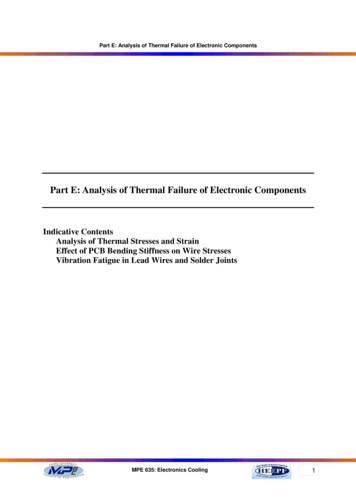
TEMPERATURE OR VOLTAGE MEASURING DEVICETHERMOCOUPLECONNECTNG CONDUIT WIRETHERMAL CUTOFF "DUMMY"TERMINAL OR SPLICEELECTRICAL INSULATORFigure 6Figure 6 illustrates a typical installation of a TTTS. Note that the body of the TTTS is at the samepotential as the connecting circuit; therefore, it must be electrically isolated from the surfaceagainst which the cutoff is mounted. Also note that the thermocouple wire is at the same potential as the connecting circuit.CAUTION . . . To avoid a false reading of the unit under test, thermocouple wires must not makecontact with each other except at the temperature sensing junction.CAUTION . . . Ensure that the thermocouple wire insulation will provide isolation against shortcircuiting and shock hazards.CAUTION . . . The terminal of the temperature measuring instrument, to which the thermocoupleis attached, will be at the same potential as the connecting circuit wire. This instrument mustbe electrically isolated and considerable caution must be exercised in its use, since one of thethermocouple terminals is frequently grounded to the instrument chassis.Before using measuring equipment powered directly from standard line voltages, check operationmanuals. Be sure line voltages impressed on the thermocouple wires by the TTTS will not causedamage to the instrument.The more closely the actual operating and ambient conditions can be simulated during test, themore valid the test results will be. These tests are necessary to empirically include the variablefactors that need to be considered to select the properly rated thermal cutoffs. These factorsinclude, but are not limited to, the heating effect of the current through the cutoff, adjoining11
terminals and leads, heating or cooling effect of the terminals and external leads, rate oftemperature rise, air flow, shock, vibration and other environmental and operating conditionsunique to the application.The product and application being tested will determine the number of cycles that must be run todetermine the maximum “normal” operating temperature. “Overshoot” temperatures should beincluded in the determination of the maximum “normal” operating temperature. The overshoottemperature is often considerably higher than the temperature reached at the moment thethermostat opens. The conclusion of these tests will provide the maximum “normal” operatingtemperature at the thermal cutoff (at maximum anticipated voltage, ambient temperature, etc).The overshoot temperature seen by the thermal cutoff after the thermal cutoff opens in theapplication must also be carefully examined and compared to Tmax.Manufacturing tolerances and variations should be carefully considered, and a sufficient numberof units evaluated, to provide a statistical basis on which to determine the operating overshoottemperatures.After obtaining the above information, test the product under fault conditions and monitor todetermine that desired fault condition temperatures are not exceeded.Where there are a variety of fault conditions, (e.g., short-circuited thermostats and transformersecondaries, locked motor rotors and solenoids, high ambient temperatures, restricted orblocked airflow, etc.), consideration should be given to multiple fault conditions which couldoccur simultaneously during the lifetime of the product, and to faults which may cause localizedoverheating in areas away from the TCO.When the fault conditions have been set up, note the temperature of the TTTS when themaximum desired temperature limit is reached. At this point the circuit is manually interrupted.This test should be run several times, in several different units. In some applications, it will notbe possible to “save” the tested item from damage, but only prevent the product from creatingan external fire or electrical hazard. Damaged products should not be retested, since the resultsmay not be the same as with undamaged units. The MICROTEMP thermal cutoff ratings selectedshould be equal to or less than the temperature recorded at the TTTS at the time the maximumdesired temperature is reached.CAUTION . . . Excessive overshoot temperatures after the opening of the thermal cutoff may causedielectric breakdown of the thermal cutoff and allow reconduction to occur. Functional thermalcutoffs should be tested to verify proper operation of the thermal cutoffs in the application (seeMicrotemp TCO Operating Temperature Summary and Electrical Rating Summary on page 4).12
Substitute actual thermal cutoffs in a sufficient number of finished products and re-run thetests to obtain statistical verification of the results. For multiple TCO applications, test functionalthermal cutoffs under fault conditions so that the product overheats and each thermal cutoff isindependently called upon to interrupt the flow of current. Each thermal cutoff should open thecircuit independently of any other over-temperature limit controls, with product damage notexceeding an acceptable level. This test should be run using the maximum voltage and current;the thermal cutoff will be expected to interrupt and hold open.Installation of Thermal CutoffsThe performance of a MICROTEMP thermal cutoff can be affected by installation methods suchas soldering, welding, splicing, lead bending, insulation, clamping and mounting. Certain precautionsshould be taken during installation to ensure that the MICROTEMP thermal cutoff is not damaged,which may cause it to not operate in its intended manner. Likewise, care should be taken duringinstallation to ensure that the TCO in every unit experiences the expected temperature rangeenvironment previously determined during the calibration temperature selection. Thefollowing guidelines should be used to minimize undesirable conditions that can result fromimproper installation practices.Soldering LeadsThermal cutoff leads should be heat sinked during the soldering operation (see figure 7). Ifexcessive heat is conducted by the leads into the thermal cutoff, it can shorten the life of the TCO.In addition, excessive lead temperatures can damage the epoxy and possibly result in the TCOfailing to open. More heat sinking is necessary for thermal cutoffs with low temperature ratings.HEAT SINK HERESOLDERSOLDERFigure 713
Test samples should be x-rayed before and after the soldering operation. The size of the chemicalpellet should be measured with an optical comparator or a toolmaker’s microscope to verify thatno shrinkage has occurred during the soldering operation (see figure 8). The epoxy seal shouldretain its size and shape and not discolor. If the chemical pellet or the epoxy have changed size asa result of the soldering operation more heat sinking is required.EPOXY SEALBARRELSPRINGTHERMAL PELLETISOLATEDLEADTRIPSPRINGCASE &LEAD ASSEMBLYFigure 8Welding LeadsThe thermal cutoff leads may also need to be heat sinked during a welding operation (see figure9). The same precautions and tests described in the soldering section should also be followed forwelded leads.HEAT SINK HEREWELD POINTSFigure 9To avoid damaging or welding internal parts, care should be taken that none of the welding currentis conducted through the TCO. A welding current of hundreds of amperes can weld the internalparts together, resulting in the TCO failing to open.TCO leads must be supported during the weld operation to prevent breaking the thermal cutoffepoxy seal.14
Splices & TerminalsInsecure splices and terminations may produce high resistance junctions which can cause selfheating (I2R) as power is dissipated across these junctions during product operation.Heat from these hot spots can flow down the thermal cutoff leads and increase the temperatureof the thermal cutoff (see figure 10). Nuisance openings of the thermal cutoffs or degradation ofthe epoxy seal can occur as a result of the heat generated by high resistance junctions. The spliceor termination junction may initially measure low resistance, but can change to a much higherresistance after several temperature cycles. It is generally better to splice MICROTEMP thermalcutoff leads to stranded lead wires rather than solid wires as the stranded wire may be crimpedtighter and maintain better electrical contact during temperature cycling.NUTSPLICEHEAT FLOWHEAT FLOWLOCKWASHERSPLICESPLICEBOLTTERMINATIONFigure 10The temperature capabilities of the splice and/or termination should be considered. For example,solder back-up should be considered for splices of terminations in applications cycled at temperaturesexceeding 150 C.Bending LeadsWhen configuring leads, special care must be exercised in supporting the leads at each end nearthe body of the thermal cutoff so that the case will not be distorted or the epoxy will not becracked or broken. At least 0.125” (3mm) should be maintained between the epoxy seal and anylead bends (see figure 11).15
.09 MIN.70 MIN. (17.8 mm)(2.3 mm).04 MIN. RAD.(1.0 mm)Figure 11Dimensions are shown in inches (millimeters).Thermal GradientsIdeal TCO placement subjects the entire TCO case, leads, epoxy seal and internal components to auniform temperature environment.Care should be exercised in the placement of the TCO to minimize thermal gradients across theTCO body. In certain applications, the TCO can be mounted in a position where heat is conductedto the body of the TCO through one of the leads, resulting in thermal gradients across the TCO.Over time, the TCO life can be reduced by thermal gradients if the isolated (epoxy) lead is at aconsistently lower temperature than the case lead. Long term testing is recommended indetermining whether these conditions exist in the application.To minimize the effects of thermal gradients and the temperature increase of the TCO body fromthis heat flow, attach the isolated (epoxy) lead, rather than the case lead, to the heat source.TTTS can be supplied with thermocouples on both ends to facilitate gradient evaluations.Temperature LimitsThe temperatures experienced during normal operation, including expected temperature overshoots, will determine the life expectancy of the TCO. Nuisance trips can result if the thermal cutoff rating is too close to the temperatures experienced during normal operation. Thermal cutoffsof any temperature rating should not be subjected to continuous normal temperatures in excessof 200 C. Additionally, overshoot temperatures after the opening of the thermal cutoff should beminimized to avoid dielectric breakdown and reconduction of the thermal cutoff.16
CAUTION . . . The thermal cutoff may fail to open the electrical circuit under certain conditions.Distortion of the case, breaking or cracking the seal, exposing the epoxy seal to cleaning solvents,compression of the leads and current surges that exceed the operating specifications of the thermalcutoff may cause the thermal cutoff not to open. In addition, pellet shrinkage due to thermalaging under some circumstances may also result in failure to open. Finally, a very low rate oftemperature rise may produce conditions that may also result in failure to open. Care must betaken to avoid any mishandling or misapplication of the thermal cutoff.CAUTION . . . Although TCOs are highly reliable devices, a TCO may fail to open in operation forone or more of the reasons set forth above. These conditions must be taken into account by theproduct design engineer in determining the level of reliability needed for the application. If failureof the TCO to open could result in personal injury or property damage, the product design engineermay want to consider using one or more redundant TCOs of different ratings to achieve thedesired level of reliability. A number of consumer product design engineers have incorporatedredundant TCOs of different ratings in their designs for this reason.Definition of TermsMaximum Open Temperature or Rated Functioning Temperature (Tf, TF):The maximum temperature at which the thermal cutoff changes its state of conductivity to opencircuit with detection current as the only load. The rated functioning temperature is measuredduring a temperature rise of approximately 0.5 C per minute.Holding Temperature (Th, TH):Maximum temperature of the MICROTEMP TCO measured at the case end of the thermal cutoff atwhich the thermal cutoff can be maintained for a period for 168 hours without opening. NOTE: it isadvised that TCOs are not exposed to continuous operating temperatures in excess of Tf -25 C.Maximum Overshoot Temperature or Maximum Temperature Limit (Tm, TM):The maximum temperature at which the thermal cutoff, having changed its state of conductivity,can be maintained at twice rated voltage for a specified period of time, during which itsmechanical and electrical properties will not be impaired.Rated Voltage:The maximum voltage that can be applied to the circuit in which the thermal cutoff is used.Rated Current:The maximum current that the thermal cutoff is rated to interrupt at the rated voltage.17
Agency RecognitionMICROTEMP thermal cutoffs are recognized by the following major agencies:PSEULBEABMETICSACCCV
1 Upper Limit Temperature Protection MICROTEMP thermal cutoffs from Therm-O-Disc offer an accurate, reliable solution to the need for upper limit temperature protection. Known as a thermal fuse, thermal link, or TCO, the MICROTEMP thermal cutoff provides protection against overheating by interrupting an electrical circuit when operating temperatures exceed the rated temperature of the cutoff.