Transcription
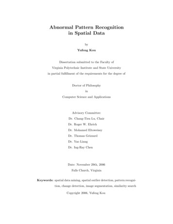
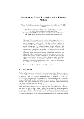
SAM: Enabling Practical Spatial Multiple Access inWireless LANKun TanMicrosoft Research AsiaBeijing, Chinakuntan@microsoft.comWei Wang,Jiansong ZhangMicrosoft Research AsiaBeijing, China{wei.wang, jiazhang}@microsoft.comHe Liu Ji FangMicrosoft Research Asiaand Tsinghua UniversityBeijing, Chinav-hliu@microsoft.comMi ChenMicrosoft Research Asiaand Beijing Jiaotong UniversityBeijing, Chinav-fangji@microsoft.com Geoffrey M. VoelkerMicrosoft Research Asiaand SouthEast UniversityBeijing, ChinaUniv. of California San DiegoLa Jolla, CA, USAvoelker@cs.ucsd.eduKeywordsABSTRACTSpatial multiple access holds the promise to boost the capacity ofwireless networks when an access point has multiple antennas. Dueto the asynchronous and uncontrolled nature of wireless LANs,conventional MIMO technology does not work efficiently whenconcurrent transmissions from multiple stations are uncoordinated.In this paper, we present the design and implementation of a crosslayer system, called SAM, that addresses the challenges of enablingspatial multiple access for multiple devices in a random access network like WLAN. SAM uses a chain-decoding technique to reliably recover the channel parameters for each device, and iteratively decode concurrent frames with misaligned symbol timingsand frequency offsets. We propose a new MAC protocol, calledCCMA, to enable concurrent transmissions by different mobile stations while remaining backward compatible with 802.11. Finally,we implement the PHY and MAC layer of SAM using the Sorahigh-performance software radio platform. Our evaluation resultsunder real wireless conditions show that SAM can improve networkuplink throughput by 70% with two antennas over 802.11.Spatial Division Multiplexing, MIMO, Software radio, wireless1. INTRODUCTIONMultiple-input and multiple-output (MIMO) is an emerging technology to significantly boost network capacity by exploiting thespatial properties of wireless channels. It has been included inseveral wireless standards, notably IEEE 802.11n, for which manycommercial devices already exist. For example, Figure 1(a) showsa device (station 3) with two antennas. When communicating withthe AP with multiple antennas, station 3 can transmit separate frameson each antenna simultaneously, and thus potentially improve itslink capacity by a factor of two.APSta4Sta1C.2.1 [COMPUTER-COMMUNICATION NETWORKS]: Network Architecture and Design—Wireless communicationGeneral TermsAlgorithms, Design, Experimentation, Performance This work is done when He Liu, Ji Fang and Mi Chen are researchinterns in Microsoft Research Asia.Permission to make digital or hard copies of all or part of this work forpersonal or classroom use is granted without fee provided that copies arenot made or distributed for profit or commercial advantage and that copiesbear this notice and the full citation on the first page. To copy otherwise, torepublish, to post on servers or to redistribute to lists, requires prior specificpermission and/or a fee.MobiCom’09, September 20–25, 2009, Beijing, China.Copyright 2009 ACM 978-1-60558-702-8/09/09 . 10.00.Sta4Sta1Sta2Categories and Subject DescriptorsAP(a)Sta3Sta2Sta3(b)Figure 1: (a) MIMO and (b) “virtual MIMO” (spatial multipleaccess).With single-user MIMO, the capacity improvement is boundedby the number of transmitter or receiver antennas, whichever issmaller. In practice, due to size, cost, and power limitations, mobilestations generally have only a few antennas (e.g., most 802.11n devices have only two antennas). However, APs do not have the sameconstraints as mobile stations, can be generously provisioned withresources, and potentially have a much larger number of MIMO radios. Nevertheless, the network capacity will not improve beyondthe link capacity as constrained by the number of antennas at themobile station.Previous results in information theory [17] indicate that it is possible for multiple stations to form a “virtual MIMO” system inwhich the stations transmit simultaneously (spatial multiple access).In this kind of network, the AP may still be able to decode allframes correctly as long as the number of concurrent frames is lessthan the number of antennas at the AP. As shown in Figure 1(b),
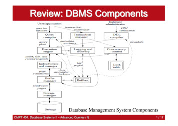
with spatial multi-access, all stations can transmit simultaneouslyto make full use of the AP’s antennas. Thus, the network capacity can increase linearly with the number of antennas at the AP,precisely the device in the network that can best accommodate thecost, size, and power of a relatively large number of radios.In this paper, we presents SAM, a practical system that enablesspatial multiple access for uplink traffic in uncontrolled wirelessLANs, and thereby indirectly increases the throughput of downlinktraffic 1 . In SAM, there is no need for mobile stations to tightlysynchronize their carrier frequency or timing to the APs, nor do devices need to exchange channel state information. With SAM, mobile stations can coordinate their transmissions in a fully distributedfashion, thereby utilizing the spatial wireless channel without relying upon AP coordination. Such distributed coordination is a goodmatch to the requirements of typical wireless LANs, as well as adhoc networks where multiple mobile stations may communicate ina peer-to-peer mode.Implementing spatial multiple access in wireless LAN confrontsa series of technical challenges, ranging from the inability to physically align symbol timing or carrier frequency among different stations (necessary for APs to correctly decode concurrent frames), tothe lack of a MAC protocol to encourage and coordinate concurrent accesses. SAM addresses these challenges with two innovative techniques, a new transmission and decoding structure calledchain-decoding that exploits the asynchronous nature of simultaneous transmissions to fully decode all concurrent frames, and anovel distributed MAC protocol called Carrier Counting MultipleAccess (CCMA) where stations independently observe and compete for concurrent transmission opportunities.We have implemented SAM in a high-speed software radio platform. In our current implementation, SAM operates over a realIEEE 802.11b network with four different modulation rates: 1, 2,5.5 and 11Mbps. With each station equipped with one antenna andan AP with two antennas, we show SAM improves the networkuplink capacity by 45–76% at 5.5Mbps, and 31–61% at 11Mbpsmodulation rate. Further, SAM remains backward compatible andinteroperable with standard 802.11 implementations. Indeed, in ourexperiments one of the mobile stations uses a commercial 802.11NIC.In summary, this paper makes three major contributions withSAM: (1) the design and implementation of the chain-decodingstructure that can effectively decode concurrent transmissions fromasynchronous senders in wireless LANs; (2) the design and implementation of the Carrier Counting Multiple Access (CCMA) MACprotocol to coordinate spatial multi-access; and (3) an experimental evaluation of SAM over a real IEEE 802.11b network. To thebest of our knowledge, SAM is the first working system to enablespatial multiple access in a high-speed wide-band wireless LANenvironment.The rest of the paper is organized as follows. Section 2 providesbackground on MIMO and spatial multiple access, and lays outthe technical challenges in implementing them in high-speed andwide-band wireless systems. We next describe in detail the twocore components of SAM, namely chain-decoding and CCMA, inSections 3 and 4, respectively. After describing our implementationof SAM using a high-performance SDR platform in Section 5, weevaluate the performance of SAM in Section 6. Finally, Section 7discusses related work and Section 8 concludes.1Admittedly somewhat irregular, we simply preferred the suggestive name SAM over the strict acronym SMA.2. BACKGROUND AND CHALLENGESIn this section we provide background on wireless communication fundamentals and single-user multiple-input multiple-output(MIMO) systems. We then describe spatial multiple access and thechallenges of implementing a practical spatial multi-access systemin a typical wireless LAN environment.2.1 A Wireless Communication PrimerIn digital communication, a baseband wireless signal is represented as a series of discrete complex numbers. Each number,called a symbol, represents certain bits of information. For example, in BPSK, symbol ejπ represents bit “0” and symbol ej0represents bit “1”. When transmitting, the series of wireless symbols is fed to a D/A convertor in a fixed interval T . We denote x[n]the complex symbol transmitted at time nT . Then, the basebandsignal is multiplied by a high-frequency carrier signal and emittedthrough an antenna. At the receiver, the baseband signal is first separated from the carrier and then digitized by an A/D convertor intodiscrete-time samples. We denote y[n] the sampled value at the receiver. In general, we can also use vector y to present all receivedsymbols, and vector x for all transmitted symbols. In a simple flatfading channel, e.g. narrow band wireless, we havey[n] h[n]x[n] w[n],(1) jθ[n]where h[n] α[n]eis a single complex number representing the channel attenuation (α[n]) and the phase shift (θ[n]) on thetransmitted symbol. In principle, a receiver must correctly recoverthe original transmitted symbols x from the distorted receive symbols y.Amplitudereal sampling timetideal sampling timeInter-symbol interferenceFigure 2: Symbol timing offset and inter-symbol interference.Before the receiver can demodulate the received signals, it musthave accurate knowledge of the wireless channel parameters. First,the receiver must know the exact symbol timing, i.e., the signal’s“ideal sampling points” which will provide the best reading forthe symbols and minimize intersymbol interference (ISI), a phenomenon where the wave of a symbol spills over onto the neighboring symbols (Figure 2). Due to propagation and Doppler effects, and the receiver’s sampling clock being independent of thesender’s, it is highly unlikely that the receiver will sample at theexact symbol time. The receiver must either accurately track thistiming offset, or it may apply over-sampling to take samples at asmaller interval (an integer fraction of T ) and interpolate the idealsample values as if they were taken at the ideal sampling points.Second, in a real system the high frequency carrier signal is generated with an electronic circuit called a crystal oscillator. Undercurrent engineering constraints, all oscillators have a small variation which will cause a slight difference between the sender andreceiver’s carrier frequency and a phase rotation in any receivedsignals. This variation will accumulate over time and cause decoding failure. For example, typical oscillators used in wireless communications today stablize at the order of parts per million (ppm),
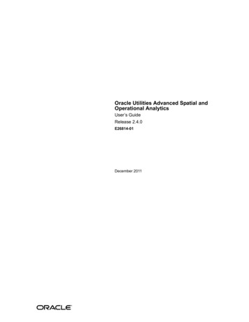
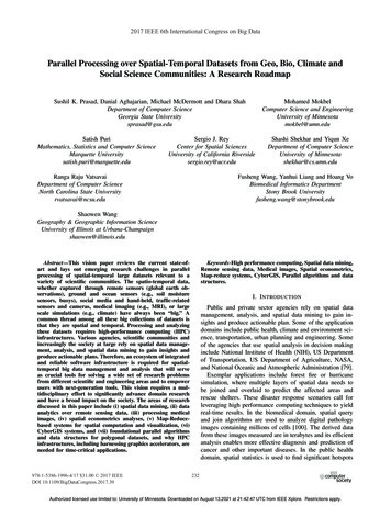
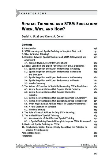
meaning that severe phase distortions can happen at a millisecondtimescale in 2.4GHz. In a real system this carrier frequency offset must be precisely estimated and compensated for when solvingEquation 1 above.Node 1Node 2Figure 4: Example of single-user 2x2 MIMO.a separate preamble, one-by-one and non-overlapping, so that eachreceiving antenna can receive a clean preamble from each transmitting antenna.2.3 Spatial Multiple Access and TechnicalChallengesFigure 3: Illustration of multi-path fading. The left figureshows the transmitted signal, and the right figure shows theactual received signal in a real environment.Third, wide-band communication is always subject to multi-pathfading [15] (see Figure 3 for an illustration). That is, the wirelesschannel instead should be represented by a vectorh {h L , ., h0 , ., hL },where each component represents a path that the signal traverses.Then the received signal y[n] becomes y[n] h x[n] w[n]where is the convolution operation. To revert the distortion dueto multi-path fading, a receiver must apply a linear filter c such thatx̂[n] c y[n].(2)Such an equalizer must be first properly trained under the samemulti-path fading channel.To summarize, a receiver must first know these critical systemparameters before it can reliably decode a frame. To facilitate this,many wireless systems such as WiFi adopt a self-training scheme:it prepends each transmission frame with a series of known training symbols called the preamble. If the preamble is received in aclean channel, the receiver can accurately estimate the symbol timing, carrier frequency offset, and channel coefficients (equalizer)necessary to properly decode the subsequent frame.2.2A MIMO PrimerIn a MIMO system, if antennas are separated properly, eachtransmitting and receiving antenna pair can have a channel differentfrom the others. For example, in a 2x2 MIMO system illustratedin Figure 4, two simultaneous transmissions can occur. Two receiving antennas can be represented with the following two linearequations:The number of concurrent transmissions in a MIMO system isalways limited to the number of antennas at the sender or the receiver, whichever is smaller. If an AP in a wireless LAN has moreantennas, it makes sense to allow more stations to access the wireless channel concurrently to make full use of the number of receiving antennas at the AP. In the example of Figure 1(b), the AP hassix antennas and each station has only one or two. In this case, thefour stations can form a “virtual MIMO” system and transmit sixframes simultaneously to the AP, achieving six times the capacityin theory.To implement this “virtual MIMO” system in a wireless LAN,there are several difficult technical challenges. First, the transmitting antennas are now distributed across several independent sending stations, and there is no guarantee of an interference-free transmission of their preambles. This preamble interference will significantly affect the accuracy of channel estimations and may resultin the loss of all concurrent frames. One naive solution is to apply excessively long preambles to each frame to average out theimpact of interference, but doing so will impose significant overhead in the communication system. A more practical approach is todevelop a distributed preamble scheme to enable interference-freedecoding despite interference from other concurrent transmissions,while minimizing the overhead of the preambles on the concurrentchannel.AmplitudeS1S2t(3)Figure 5: Unsolvable symbol timing mis-match in spatial multiaccess.where wi is the noise, and hij is the complex channel coefficientvector for the multi-path channel between the sending and receivingantenna pair. As long as the channels are orthogonal, meaning thatthe equations will be linearly independent, both x1 and x2 can beresolved.For the same reason as described in the previous subsection, aMIMO receiver must first acquire knowledge of all channels between any transmitting/receiving antenna pairs, including their symbol timing, frequency offset, and channel coefficients. This acquisition can be achieved with a simple extension of the preamble scheme, as in 802.11n where each transmitting antenna sendsSecond, the fact that transmitting antennas are not driven fromthe same oscillators introduces further challenges in decoding concurrent frames. In a simple MIMO system, all transmitting antennas have the same symbol timing and frequency offset. In a “virtualMIMO” system, however, when signals from multiple sending stations superimpose together at one of the AP’s receiving antenna,neither their symbol timings nor their frequency offsets will aligntogether. In particular, there may no longer exist “ideal samplingpoints”. As illustrated in Figure 5, at the times when the intersymbol interferences from one signal are minimized, the intersymbolinterferences from another signal become high. That is, no matter how much over-sampling the receiver can perform, the samplesy1 [n] h11 x1 [n] h12 x2 [n] w1 [n]y2 [n] h21 x1 [n] h22 x2 [n] w2 [n]
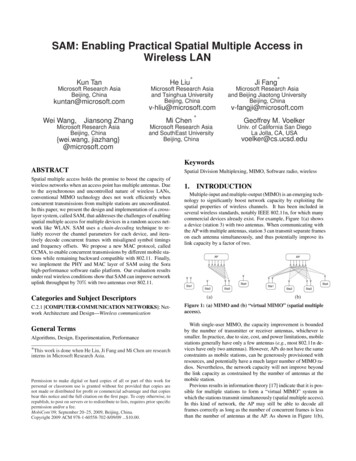
are always distorted by interference. This misalignment essentiallymeans Equation 3 can never be satisfied in spatial multi-access,and a conventional single user MIMO decoder will not work. Priorwork on this problem focuses on tight synchronization among allsending stations [2], but such an approach requires very complicated electronics that may not suit environments like loosely controlled wireless LANs.Both problems must be solved to enable spatial multi-access inwireless LANs. The fundamental challenge derives from the distributed nature of concurrent transmissions from unsynchronizedstations. This challenge calls for a cross-layer PHY/MAC solutionto exploit spatial multiplexing in a distributed and unsynchronizedmethod.3.CHAIN-DECODINGSAM enables spatial multiple access in wireless LANs by allowing multiple concurrent transmission to be mostly overlapped:a latter frame will start transmission after the end of the preamble of a former frame. In Figure 6(a), we show an example oftwo frames that are partially overlapped in this manner. SAM usesa decoding structure, called chain-decoding, that can reliably decode the frames in an overlapping transmission. In this section,we describe the steps involved in chain-decoding overlapped transmissions, and in the next section we describe a straightforwardbackwards-compatible MAC protocol that enables stations to takeadvantage of chain-decoding. For the sake of simplicity, in the following we focus on the case where only the AP has multiple antennas and all mobile stations have one antenna. It is straightforwardto extended the scenario to the case where mobile nodes in the network also have multiple antennas.using the redundant antennas for diversity selection or maximal radio combining (MRC) [3]. Later, in Section 3.3, we generalizechain-decoding to the case where more stations spatially access thechannel.When the AP receives these two overlapped transmissions at itstwo antennas, it performs the following two steps to decode eachframe:1. Interference nullifying. In the first step, the AP nullifies thesignal of Pa from both received signals, y 1 and y 2 . Then, itwill obtain a version of the signal containing only Pb whichis ready for decoding.2. Interference cancelation. After Pb is successfully decoded,it can be re-encoded and canceled from the original signals,y 1 and y 2 . Such cancelation will result in signals containingonly Pa . Thus, Pa is then ready for decoding.3.1Interference NullifyingFrom the AP’s point of view, the received signals y i are superpositions of the two signals of Pa and Pb , denoted as x1 and x2 ,that pass different wireless channels. We can use a vector to presenta received signal. In Figure 7(a), we show the relation among thereceived signal y i and the channel distorted signal versions of xi .The idea of interference nullifying (IN) is to find two proper lineartransforms for y 1 and y 2 such that, after transformation, the signalsfor one frame, say x1 , are aligned with exactly the same directionand scale, as shown in Figure 7(b). Then, a substraction of thesetwo transformed signals will completely remove x1 . The result isanother signal y 3 which contains only the information of x2 and isready for decoding.y1R1y1h12x2y1R1h11x1PbAntenna 2APR2h22x2h22Sta2R2y2Antenna 2y2PbPa(a) Two stations transmit two frames concurrently.y1y2PbPbPaPa(b) AP performs interference nullifying to remove the signal ofPa . Then, Pb is ready for decoding.y1PbPay2PbPa(c) After decoding Pb , AP applies interference cancelation toremove the signal of Pb . Then, Pa is ready for decoding.Figure 6: Illustration of chain decoding.We start with the basic example in Figure 6(a) where two stations transmit concurrently. Without loss of generality, we assumethat AP selects two received signals from antenna 1 and 2 (labeledy1 and y2 , respectively) for decoding. Note that the AP may havemore than two antennas, and it can further improve reliability byR2h22x2h21x1(a)(b)(c)Figure 7: Illustration of interference nullifying.Although there can be multiple ways to align the signals, themost natural way is to recover the signals to the original x1 that istransmitted, which is an operation that should be done in any communication system. Since we have a clean preamble of Pa , we caneasily estimate the necessary system parameters of Pa , includingsymbol timing and carrier frequency offset, using standard mechanisms for single-user communication [11]. However, particularattention should be paid to the design of the equalizer that removesthe distortion due to multi-path fading.(a) Channel equalizer for interference nullifyingAs mentioned earlier, an equalizer is a linear filter c {c L , ., cL }that reverses the impact of a multi-path wireless channel. Mathematically, an optimal equalizer minimizes the difference betweenthe recovered signals and the signals that were transmitted, as:c arg min x c y ,c
Figure 8: Pseudo-code for equalizer training algorithms. Thesame algorithm also applies to channel estimation with the exchange of input and output.where x is the transmitted signal, y is the received signal, . represents the 2-norm, and “ ” is the convolution operation.To obtain each component value of c, the receiver uses the knownpreamble to train the equalizer with an adaptive searching algorithm. Figure 8(a) outlines the Normalized Least Mean Square algorithm for an adaptive equalizer [15]. However, a conventionalequalizer works at the symbol rate and it can only capture the signal path with a delay that is an integer multiple of the symbol time,and compensate the values at the ideal sampling point. This capability is sufficient for synchronized single-user MIMO since onlythese ideal sample points are useful for decoding.However, for IN, when signals of multiple transmitters are misaligned, a symbol-rate equalizer is not sufficient. Figure 9 illustrates this issue. In Figure 9, we transmit a single frame and perform IN based on the two received signals. Since there is only oneframe, the result of IN should be pure noise. Figure 9(a) showsthe energy of the original signal and (b) shows the results of IN.We can see that with a conventional symbol-rate equalizer, peaksof residual energy remain which are due to the multi-path signalswith fractional delays. In overlapped transmission, since the symbol timing is mis-aligned such residual energy will still cause interference to the remaining frame if they happen to overlap at theideal sampling points.To address this problem, in SAM we use an equalizer that workswith over-sampling. Currently, we use four-time over-sampling inour system. Such an equalizer is usually referred to as a fractionalspaced equalizer (FSE) [15]. However, unlike a conventional FSEwhich only trains an equalizer to minimize the mean square error atthe ideal sampling points, in IN, the equalizer is trained to minimizethe mean square error of all over-sampling points.Such an approach immediately raises the following issue. Thetransmitter only specifies the value at the sampling point. Whatshould be the expected values at the over-sampling points? Fortunately, we can get these expected values using interpolation from itsnearby sample point values. For example, in 802.11b all transmitted samples are shaped with a root-raised cosine function. Thus,we can interpolate the fractional point values using the square ofthe power-shaping filter asx̃(nT τ ) LXx(nT iT )R(nT τ iT ),i Lwhere T is the symbol interval, R(.) is the root-raised cosine function, and τ is the fraction of sampling time. When using four-time.over-sampling, τ can be T4 , T2 , and 3T4The algorithm outlined in Figure 8(a) can still be applied without modification, as long as the input of xi and yi are all oversampling values, and each tap of c represents the coefficient on anover-sampling point. At each iteration, an estimation of error between the desired value and the recovered value is calculated. Weuse this error to drive the coefficient vector in the gradient direction with a step size controlled by (line 10). When the searchingconverges, c {cj } is the optimum equalizer we need.During our implementation, however, we found that the basic algorithm in Figure 8(a) is sensitive to the input data and may be unstable when some samples are extremely tiny (deep fading), whichmay cause an unreasonably large update in the coefficients. Although the situation could be controlled with a very tiny , thetradeoff is a correspondingly slower convergence speed. Thus, wemodify the basic algorithm with a more stable version, as shown inFigure 8(b). Instead of adjusting for every sample, we calculate aweighted average over a block of K samples and use this average toupdate the coefficient vector. As shown by lines 7–16, we calculatean “averaged” estimation of the gradient as a result.Figure 9(b) shows the results of our equalizer. After equalization, multi-path distortion can be effectively mitigated and over90% of the original signal energy can be nullified.(b) Decoding of remaining frame after INAfter IN, it is now straightforward to decode Pb . Since the interference of Pa has been removed, the preamble of Pb is now clean.So the receiver can re-synchronize to Pb , estimate the frequencyoffset and channel parameters and decode it using the normal decoder. Note that this wireless channel is actually a combined effectof the original wireless channels (Hi,j , i, j 1, 2).x1000400Energy(a)1: Initializer {ci }:2: c0 13: cj 0, j 6 04:5: Training:6: for each sample i do7: for k 0.K 1 doPL8:x̂i k c yl L l i k l9:²k xi k x̂i k10:δj 0, j L.L11:w 012:for j L.L do 13:δj δj · ²k yi k j14:w w yi k j 215:end for16: end for17: for j L.L do18:cj cj δj /w19: end for20: end for(b)3002001000020406080(a)x100040Energy1: Initialize {ci }:2: c0 13: cj 0, j 6 04:5: Training:6: for each sample i doP7: x̂i Lc yl L l i l8: ² xi x̂i9: for j L.L do²y 10:cj cj · y i j 2i j11: end for12: end forConventional chip-rate equalizer30Our fractioanl-rate equalizer20100020406080(b)Figure 9: Equalization for interference nullifying in multi-pathfading channel. IN is performed on a single frame transmittedto two receiving antennas. (a) Original interference signal. (b)The nullifying results with the conventional equalizer and ourextended equalizer design.3.2 Interference CancelationAfter Pb is decoded, it can be re-encoded and canceled from theoriginal signals. To cancel Pb , the AP must regenerate a series of
samples, each of which has the exactly same phase shifting causedby the sample timing offset, carrier frequency offset, and the samedistortion of the wireless channel. Assuming all this informationis known, the generation of symbols of Pb at receiving antenna itakes the following steps:1. Re-generate timing offset. We first need to generate theeffect of the timing offset between the sender and receiver.Again, we use interpolation to obtain values at the receiver’ssampling points, withỹi (nT τ ) LXa new block, and a block should always contain whole preambles.After each block is decoded, the decoded symbols are used as training symbols to update the estimations of frequency offset and symbol timing for all transmitters. The size of the block depends on theaccuracy of the estimations; it can be larger if the estimation has ahigh accuracy. In our experience, a block less than 3ms has beensufficient for accurately tracking these parameters.Pby1Pax(nT jT )R(nT τ jT ),j L2. Re-generate frequency offset. Then, we add the phase shiftcaused by the frequency offset, usingj2π f (nT τ )ŷi [nT τ ] ỹi (nT τ )e.3. Re-generate channel distortion. Finally, we pass the generated samples through a channel filter to add the multi-pathdistortions,yi [nT τ ] hi2 ŷi [nT τ ],where hi2 represents the channel vector between the ith receiving antenna and the sending antenna of Pb .Recall that, when decoding Pb , the receiver can already estimatethe frequency offset and symbol timing of Pb , and the only unknown factor are the wireless channel coefficients. One challengeis that the preamble of Pb overlaps with Pa . Thus, as mentionedearlier, when purely relying on the preamble we cannot get a precise estimation of the channel coefficients. Fortunately, since wehave already decoded Pb , we can use all of Pb as training symbolsand thereby can greatly mitigate the impact of the interference fromPa .Channel estimation is similar to finding an equalizer, but now wefind a vector h, such thatPby2where R(.) is the root-raised cosine function and τ is theestimated sampling offset.PaB1B2B3B4Figure 10: The tracking mode of chain-decoding. A long frameis divided into blocks. Chain-decoding decodes each block sequentially. The decoded symbols are then used for updating thesymbol timing and frequency offset.3.4 More than Two Frames OverlappedIt is straightforward to extend chain-decoding to N -antenna case.With N frames overlapped, the AP first uses the N received signalsto nullify the first frame and get overlapped signals containing theN 1 frames. Then, we repeat the interference nullifying processto nullify proceeding frames. When only the last frame remains,the AP can decoded it and canceled it from the original frames.Then, recursively, all frames can be decoded. Note that the sameprocedures also apply to the tracking mode, where instead of thewhole frame each block of the transmission is processed.3.5DiscussionSAM has the promise of linearly increasing of network capacitywith the number of antennas at the AP by enabling spatial multiaccess in WLANs. The major advantage of the chain-decodingmethod is that it does not require any strict synchronization between transmitters. It is also quite general because it works onh arg min y h x ,hvarious modulation schemes and with multi-carrier systems suchwhere x is the transmitted signal, y is the received signal, and “ ”as OF
layer system, called SAM, that addresses the challenges of enabling spatial multiple access for multiple devices in a random access net-work like WLAN. SAM uses a chain-decoding technique to re-liably recover the channel parameters for each device, and itera-tively decode concurrent frames with misaligned symbol timings and frequency offsets.