Transcription
LP141WX3Liquid Crystal DisplayProduct SpecificationVer. 1.0Jan. 28, 20080 / 31
LP141WX3Liquid Crystal DisplayProduct SpecificationSPECIFICATIONFORAPPROVAL() Preliminary Specification( ) Final SpecificationTitleCustomer14.1” WXGA TFT LCDSUPPLIERLenovo*MODELMODELLG.Philips LCD Co., Ltd.LP141WX3SuffixTLP1*When you obtain standard approval,please use the above model name without suffixAPPROVED BYAPPROVED BYSIGNATURESIGNATUREK.S. Kwon / G.Manager/REVIEWED BY/W.Y. Park / Manager/PREPARED BYM.K. Bae / EngineerJ.W. Kim / EngineerPlease return 1 copy for your confirmation withyour signature and comments.Ver. 1.0Jan. 28, 2008Products Engineering Dept.LG. Philips LCD Co., Ltd1 / 31
LP141WX3Liquid Crystal DisplayProduct RD OF REVISIONS31GENERAL DESCRIPTION42ABSOLUTE MAXIMUM RATINGS53ELECTRICAL SPECIFICATIONS3-1ELECTRICAL CHARACTREISTICS63-2INTERFACE CONNECTIONS83-3LVDS SIGNAL TIMING SPECIFICATIONS93-4SIGNAL TIMING SPECIFICATIONS113-5SIGNAL TIMING WAVEFORMS113-6COLOR INPUT DATA REFERNECE123-7POWER SEQUENCE134OPTICAL SFECIFICATIONS145MECHANICAL CHARACTERISTICS176RELIABLITY247INTERNATIONAL STANDARDS7-1SAFETY257-2EMC258PACKING8-1DESIGNATION OF LOT MARK268-2PACKING FORM26PRECAUTIONS27APPENDIX. Enhanced Extended Display Identification Data299AVer. 1.0Jan. 28, 20082 / 31
LP141WX3Liquid Crystal DisplayProduct SpecificationRECORD OF REVISIONSRevision No Revision DatePageDescriptionEDIDver0.0Oct. 15. 2007-First Draft (Preliminary Specification)0.10.1Dec. 13. 200729 31EDID update(be uadated product code)0.20.2Dec. 29. 20078Table 4. BACKLIGHT CONNECTOR PIN CONFIGURATION (J3)-Be updated high voltage side terminal color (Pink White)1.0Ver. 1.0Jan. 28. 200814Be updated Color Coordinates15Be updated Gray scale specificationFinal CASJan. 28, 20083 / 31
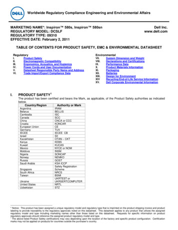
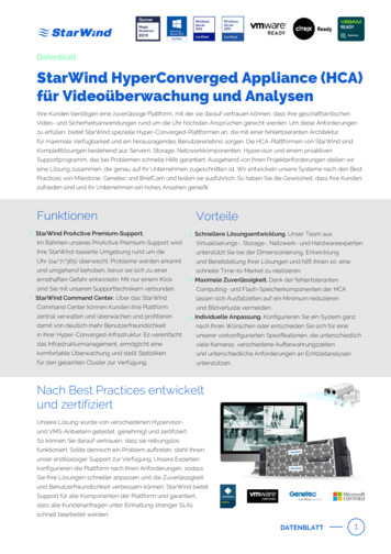
LP141WX3Liquid Crystal DisplayProduct Specification1. General DescriptionThe LP141WX3 is a Color Active Matrix Liquid Crystal Display with an integral Cold Cathode FluorescentLamp (CCFL) backlight system. The matrix employs a-Si Thin Film Transistor as the active element. It is atransmissive type display operating in the normally white mode. This TFT-LCD has 14.1 inches diagonallymeasured active display area with WXGA resolution(800 vertical by 1280 horizontal pixel array). Each pixelis divided into Red, Green and Blue sub-pixels or dots which are arranged in vertical stripes. Gray scale orthe brightness of the sub-pixel color is determined with a 6-bit gray scale signal for each dot, thus,presenting a palette of more than 262,144 colors.The LP141WX3 has been designed to apply the interface method that enables low power, high speed, lowEMI.The LP141WX3 is intended to support applications where thin thickness, low power are critical factors andgraphic displays are important. In combination with the vertical arrangement of the sub-pixels, theLP141WX3 characteristics provide an excellent flat display for office automation products such as NotebookPC.CNLVDS &TimingControlBlock1Source Driver Circuit11280GIP(Gate In Panel)User connector1POWERBLOCK30PinEDIDBLOCKTFT-LCD Panel(1280 x 800)800Backlight Ass’yCNControl & DataPowerEDID signal & PowerGeneral FeaturesActive Screen Size14.1 inches diagonalOutline Dimension319.5(H,Typ.) 205.5(V,Typ.) 5.5(D,Max) [mm]Pixel Pitch0.2373mm 0.2373 mmPixel Format1280 horiz. By 800 vert. Pixels RGB strip arrangementColor Depth6-bit, 262,144 colorsLuminance, White200 cd/m2(Typ.5 point)Power ConsumptionTotal 5.2 Watt(Typ.) @ LCM circuit 1.2 Watt(Typ. Mosaic), B/L input 4.0Watt(Typ.)Weight400g(Max.)Display Operating ModeTransmissive mode, normally whiteSurface TreatmentAnti glare treatment of the front polarizerRoHS ComplyYesVer. 1.0Jan. 28, 20084 / 31
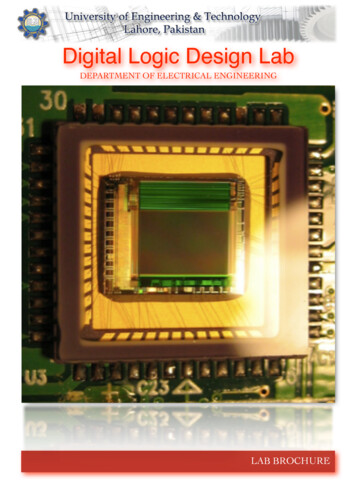
LP141WX3Liquid Crystal DisplayProduct Specification2. Absolute Maximum RatingsThe following are maximum values which, if exceeded, may cause faulty operation or damage to the unit.Table 1. ABSOLUTE MAXIMUM RATINGSParameterValuesSymbolMinMaxUnitsNotesPower Input VoltageVCC-0.34.0Vdcat 25 5 COperating TemperatureTOP050 C1Storage TemperatureHST-2060 C1Operating Ambient HumidityHOP1090%RH1Storage HumidityHST1090%RH1Note : 1. Temperature and relative humidity range are shown in the figure below.Wet bulb temperature should be 39 C Max, and no condensation of water.90% 80%60%605040%40302020%10Humidity[(%)RH]Wet BulbTemperature [ ]StorageOperation010%-2001020304050607080Dry Bulb Temperature [ ]Ver. 1.0Jan. 28, 20085 / 31
LP141WX3Liquid Crystal DisplayProduct Specification3. Electrical Specifications3-1. Electrical CharacteristicsThe LP141WX3 requires two power inputs. One is employed to power the LCD electronics and to drive theTFT array and liquid crystal. The second input which powers the CCFL, is typically generated by aninverter. The inverter is an external unit to the LCD.Table 2. ELECTRICAL otesMODULE :Power Supply Input VoltageVCCICCPower 1Zm90100110Ohm2VBL640(7.0mA)Operating CurrentIBL2.06.07.0mARMSPower ConsumptionPBL1.84.04.5WOperating FrequencyfBL455580kHzDischarge Stabilization TimeTs3Min415,000Hrs511801415VRMSVRMSDifferential ImpedancePcMosaicLAMP :Operating VoltageLife TimeEstablished Starting Voltageat 25 at 0 Vs670(6.0mA) 880(2.0mA)VRMS3Note)1. The specified current and power consumption are under the Vcc 3.3V , 25 , fv 60Hz conditionwhereas Mosaic pattern is displayed and fv is the frame frequency.2. This impedance value is needed to proper display and measured form LVDS Tx to the mating connector.3. The typical operating current is for the typical surface luminance (LWH) in optical characteristics.4. Define the brightness of the lamp after being lighted for 5 minutes as 100%, Ts is the time required forthe brightness of the center of the lamp to be not less than 95%.5. The life time is determined as the time at which brightness of lamp is 50% compare to that of initial valueat the typical lamp current.Ver. 1.0Jan. 28, 20086 / 31
LP141WX3Liquid Crystal DisplayProduct SpecificationNote)6. The output of the inverter must have symmetrical(negative and positive) voltage waveform andsymmetrical current waveform.(Asymmetrical ratio is less than 10%) Please do not use the inverterwhich has asymmetrical voltage and asymmetrical current and spike wave.Lamp frequency may produce interface with horizontal synchronous frequency and as a result this maycause beat on the display. Therefore lamp frequency shall be as away possible from thehorizontal synchronous frequency and from its harmonics in order to prevent interference.7. It is defined the brightness of the lamp after being lighted for 5 minutes as 100%.TS is the time required for the brightness of the center of the lamp to be not less than 95%.8. The lamp power consumption shown above does not include loss of external inverter.The applied lamp current is a typical one.9. Requirements for a system inverter design, which is intended to have a better display performance, abetter power efficiency and a more reliable lamp, are following.It shall help increase the lamp lifetime and reduce leakage current.a. The asymmetry rate of the inverter waveform should be less than 10%.b. The distortion rate of the waveform should be within 2 10%.* Inverter output waveform had better be more similar to ideal sine wave.* Asymmetry rate:Ip I p – I –p / Irms * 100%* Distortion rateI -pI p (or I –p) / Irms10. Inverter open voltage must be more than lamp voltage for more than 1 second for start-up.Otherwise, the lamps may not be turned on.※ Do not attach a conducting tape to lamp connecting wire.If the lamp wire attach to a conducting tape, TFT-LCD Module has a low luminance and the inverterhas abnormal action. Because leakage current is occurred between lamp wire and conducting tape.Ex of current wave)Normal current wave - StandardAbnormal current wave - BadAbnormal current wave - BadVer. 1.0Abnormal current wave - BadJan. 28, 20087 / 31
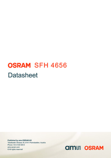
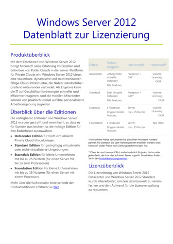
LP141WX3Liquid Crystal DisplayProduct Specification3-2. Interface ConnectionsThis LCD employs two interface connections, a 30 pin connector is used for the module electronics interfaceand the other connector is used for the integral backlight system.The electronics interface connector is a model GT101-30S-HR11 manufactured by LSC.Table 3. MODULE CONNECTOR PIN CONFIGURATION (CN1)PinSymbol1GNDGroundDescription2VCCPower Supply, 3.3V Typ.3VCCPower Supply, 3.3V Typ.4V EEDID5NCDDC 3.3V powerReserved for supplier test point6Clk EEDIDDDC Clock7DATA EEDIDDDC Data8RIN 0-Negative LVDS differential data input9RIN 0 Positive LVDS differential data input10GNDGround11RIN 1-Negative LVDS differential data input12RIN 1 Positive LVDS differential data input13GNDGround14RIN 2-Negative LVDS differential data input15RIN 2 Positive LVDS differential data inputGround16GND17CLKIN-Negative LVDS differential clock input18CLKIN Positive LVDS differential clock input19GND20NCNo Connect21NCNo ConnectNotes1, Interface chips1.1 LCD : SW, SW0612B (LCD Controller)including LVDS Receiver1.2 System : THC63LVD823A or equivalent* Pin to Pin compatible with LVDS2. Connector2.1 LCD : GT101-30S-HR11, LSCIS100-C30R-C15 ,UJU Elec.it’s compatible.2.2 Mating : FI-X30M or equivalent.2.3 Connector pin arrangement130[LCD Module Rear View]Ground22GND23NCGroundNo Connect24NCNo Connect25GND26NCGroundNo Connect27NCNo Connect28GND29NCNo Connect30NCNo ConnectGroundThe backlight interface connector is a model BHSR-02VS-1, manufactured by JST or Compatible.The mating connector part number is AMP1674817-2 or equivalent.PIN1PIN2Table 4. BACKLIGHT CONNECTOR PIN CONFIGURATION (J3)PinSymbolDescriptionNotes1HVPower supply for lamp (High voltage side)12LVPower supply for lamp (Low voltage side)1Notes : 1. The high voltage side terminal is colored Pink and the low voltage side terminal is Yellow.Ver. 1.0Jan. 28, 20088 / 31
LP141WX3Liquid Crystal DisplayProduct Specification3-3. LVDS Signal Timing Specifications3-3-1. DC SpecificationSymbolMinMaxUnitNotesLVDS Differential Voltage VID 100600mV-LVDS Common mode VoltageVCM0.61.8V-LVDS Input Voltage RangeVIN0.32.1V-Description3-3-2. AC - 400 400ps85MHz Fclk 65MHztSKEW- 600 600ps65MHz Fclk 25MHztSKEW EO- 1/7 1/7Tclk-Maximum deviationof input clock frequency during SSCFDEV- 3%-Maximum modulation frequencyof input clock during SSCFMOD-200KHz-LVDS Clock to Data Skew MarginLVDS Clock to Clock Skew Margin (Evento Odd)Ver. 1.0Jan. 28, 20089 / 31
LP141WX3Liquid Crystal DisplayProduct Specification Clock skew margin between channel Freq.FmaxFcenter * FDEVFcenterFmin1FMODTime Spread Spectrum 3-3-3. Data Format1) LVDS 1 PortRCLK RA /-R3R2R1R0G0R5R4R3R2R1R0G0R5R4RB /-G4G3G2G1B1B0G5G4G3G2G1B1B0G5RC /-B5B4B3B2DEB5B4B3B2DERD /-G7G6R7R6XG7G6R7R6XPrevious (N-1)th CycleVSYNC HSYNCB7B6Current (Nth ) CycleVSYNC HSYNCB7B6Next (N 1)th Cycle LVDS Data Format Ver. 1.0Jan. 28, 200810 / 31
LP141WX3Liquid Crystal DisplayProduct Specification3-4. Signal Timing SpecificationsThis is the signal timing required at the input of the User connector. All of the interface signal timing should besatisfied with the following specifications and specifications of LVDS Tx/Rx for its proper operation.Table 6. TIMING 10Width-ActivetWVA800800800Horizontal back porchtHBP404596Horizontal front porchtHFP244856Vertical back porchtVBP61332Vertical front ition : VCC 3.3V3-5. Signal Timing WaveformsHigh: 0.7VCCData Enable, Hsync, VsyncLow: 0.3VCCtCLKDCLK0.5 VcctHPHsync tWHtHBPtWHAtHFPtWVAtVFPData EnabletVPtWVVsynctVBPData EnableVer. 1.0Jan. 28, 200811 / 31
LP141WX3Liquid Crystal DisplayProduct Specification3-6. Color Input Data ReferenceThe brightness of each primary color (red,green and blue) is based on the 6-bit gray scale data input for thecolor ; the higher the binary input, the brighter the color. The table below provides a reference for colorversus data input.Table 7. COLOR DATA REFERENCEInput Color DataREDColorBasicColorREDGREENBLUEVer. 1.0GREENMSBBLUELSB MSBLSB MSBLSBR5R4 R3 R2 R1 R0 G5G4 G3 G2 G1 G0 B5B4B3B2Black000000 000000 000Red111111 000000 00Green000000 111111 0Blue000000 00000Cyan000000 1111Magenta111111 000Yellow111111 11White111111 1RED (00)00000RED (01)00000 B1B00000000000000 11111111 111111000 1111111111 00000011111 1111110 000000 0000001 000000 000000 RED (62)111110 000000 000000RED (63)111111 000000 000000GREEN (00)000000 000000 000000GREEN (01)000000 000001 000000. GREEN (62)000000 111110 000000GREEN (63)000000 111111 000000BLUE (00)000000 000000 000000BLUE (01)000000 000000 000001 BLUE (62)000000 000000 111110BLUE (63)000000 000000 111111Jan. 28, 200812 / 31
LP141WX3Liquid Crystal DisplayProduct Specification3-7. Power Sequence90%Power Supply For LCDVCC90%0V 10%10%T1Interface Signal,Vi(LVDS Signal of Transmitter)T5T2T7Valid Data0VT4T3OFFLAMP PowerT6LAMP ONOFFTable 8. POWER SEQUENCE T7200--(ms)Note)1. Valid Data is Data to meet “3-3. LVDS Signal Timing Specifications”2. Please avoid floating state of interface signal at invalid period.3. When the interface signal is invalid, be sure to pull down the power supply for LCD VCC to 0V.4. Lamp power must be turn on after power supply for LCD and interface signal are valid.Ver. 1.0Jan. 28, 200813 / 31
LP141WX3Liquid Crystal DisplayProduct Specification4. Optical SpecificationOptical characteristics are determined after the unit has been ‘ON’ and stable for approximately 30 minutes ina dark environment at 25 C. The values specified are at an approximate distance 50cm from the LCD surfaceat a viewing angle of Φ and Θ equal to 0 .FIG. 1 presents additional information concerning the measurement equipment and method.FIG. 1 Optical Characteristic Measurement Equipment and MethodOptical Stage(x,y)LCD ModulePritchard 880 orequivalent50cmTable 9. OPTICAL CHARACTERISTICSTa 25 C, VCC 3.3V, fV 60Hz, fCLK 71.0MHz, FBL 55kHz , IBL 6.0mAParameterSymbolValuesMinTypMaxContrast RatioCR300--Surface Luminance, whiteLWH170200-Luminance Variationδ WHITE-1.41.6Response TimeTrR TrD16UnitsNotes1cd/m223ms4Color 0.359Θr40--degreex axis, left (Φ 180 )Θl40--degreey axis, up (Φ 90 )Θu15--degreey axis, down (Φ 270 )Θd35--degreeBLUEWHITEViewing Anglex axis, right(Φ 0 )5Gray ScaleVer. 1.06Jan. 28, 200814 / 31
LP141WX3Liquid Crystal DisplayProduct SpecificationNote)1. Contrast Ratio(CR) is defined mathematically asSurface Luminance with all white pixelsContrast Ratio Surface Luminance with all black pixels2. Surface luminance is the average of 5 point across the LCD surface 50cm from the surface withall pixels displaying white. For more information see FIG 1.LWH Average(L1,L2, L5)3. The variation in surface luminance , The panel total variation (δ WHITE) is determined by measuring LNat each test position 1 through 13 and then defined as followed numerical formula.For more information see FIG 2.δ WHITE Maximum(L1,L2, L13)Minimum(L1,L2, L13)4. Response time is the time required for the display to transition from white to black (rise time, TrR) andfrom black to white(Decay Time, TrD). For additional information see FIG 3.5. Viewing angle is the angle at which the contrast ratio is greater than 10. The angles are determinedfor the horizontal or x axis and the vertical or y axis with respect to the z axis which is normal to theLCD surface. For more information see FIG 4.6. Gray scale specificationVer. 1.0* fV 60HzGray LevelLuminance [%] L5578.8L63100Jan. 28, 200815 / 31
LP141WX3Liquid Crystal DisplayProduct SpecificationFIG. 2 Luminance measuring point for surface luminance & measuring point for luminance variation HCAL6DL8L7L3VBL2L1L9H,V : ACTIVE AREAA : H/4 mmB : V/4 mmC : 10 mmD : 10 mmPOINTS : 13 POINTSL10Center PointL4L11L5L12L13FIG. 3 Response TimeThe response time is defined as the following figure and shall be measured by switching the input signalfor “black” and teblackVer. 1.0Jan. 28, 200816 / 31
LP141WX3Liquid Crystal DisplayProduct Specification5. Mechanical CharacteristicsThe contents provide general mechanical characteristics for the model LP141WX3. In addition the figuresin the next page are detailed mechanical drawing of the LCD.Outline DimensionHorizontal319.5 0.5mmVertical205.5 0.5mmThickness5.5mm (max)Horizontal306.76 0.5mmVertical193.00 0.5mmHorizontal303.74 mmVertical189.84 mmBezel AreaActive Display AreaWeightSurface TreatmentVer. 1.0400(Max)Anti glare treatment of the front polarizerJan. 28, 200817 / 31
LP141WX3Liquid Crystal DisplayProduct Specification FRONT VIEW Note) Unit:[mm], General tolerance: 0.5mmWire Length : 61mmVer. 1.0Jan. 28, 200818 / 31
LP141WX3Liquid Crystal DisplayProduct Specification REAR VIEW Ver. 1.0Note) Unit:[mm], General tolerance: 0.5mmJan. 28, 200819 / 31
LP141WX3Liquid Crystal DisplayProduct Specification[ DETAIL DESCRIPTION OF SIDE MOUNTING SCREW ]* Mounting Screw Length (A) 2.0(Min) / 2.5(Max)* Mounting Screw Hole Depth (B) 2.5(Min)* Mounting hole location : 3.7(typ.)* Torque : 2.5 kgf.cm(Max)(Measurement gauge : torque meter)Notes : 1. Screw plated through the method of non-electrolytic nickel plating is preferredto reduce possibility that results in vertical and/or horizontal line defect due tothe conductive particles from screw surface.Ver. 1.0Jan. 28, 200820 / 31
LP141WX3Liquid Crystal DisplayProduct SpecificationLPL Proposal for system cover design.(Appendix)1Gap check for securing the enough gap between LCMand System cover.1.Rearside of LCM is sensitive against external stress,and previous checkabout interference is highly needed.Define2.In case there is something from system cover comes into the boundaryabove,mechanical interference may cause the FOS defects.(Eg:Ripple,White spot.)2Check if antenna cable is sufficiently apart from T-CON of LCD Module.DefineGOODNO GOOD1.If system antenna is overlapped with T-CON,it might be cause the noise.Ver. 1.0Jan. 28, 200821 / 31
LP141WX3Liquid Crystal DisplayProduct SpecificationLPL Proposal for system cover design.3Gap check for securing the enough gap between LCMand System hinge.1.AtDefineleast 2.0mm of gap needs to be secured to prevent the shockrelated defects.2.”L” type of hinge is recommended than “I” type under shock test.4Checking the path of the System wire.#6Good#5Ok#4#3#2#1Bad1.COF area needs to be handled with care.DefineVer. 1.02.GOOD Wire path design to system side.OK Wire path is located between COFs.BAD Wire path overlapped with COF area.Jan. 28, 200822 / 31
LP141WX3Liquid Crystal DisplayProduct SpecificationLPL Proposal for system cover design.5Using a bracket on the top of LCM is not recommended.bracketWith bracketDefine6Without bracket1.Condition without bracket is good for mechanical noise,and can minimizethe light leakage from deformation of bracket.2.The results shows that there is no difference between the conditionwith or without bracket.Securing additional gap on CNT area.System cover inner side.A-1AUser connectorarea.User connectorCable pathway.A A-1cutFPC:Flexible Printed Circuit.DefineVer. 1.01.CNT area is specially sensitive against external stress,and additionalgap by cutting on system cover will be helpful on removing the Ripple.2.Using a thinner CNT will be better. (eg: FPC type)Jan. 28, 200823 / 31
LP141WX3Liquid Crystal DisplayProduct Specification6. ReliabilityEnvironment test conditionNo.Test ItemConditions1High temperature storage testTa 60 C, 240h2Low temperature storage testTa -20 C, 240h3High temperature operation testTa 50 C, 50%RH, 240h4Low temperature operation testTa 0 C, 240h5Vibration test (non-operating)Sine wave, 10 500 10Hz, 1.5G, 0.37oct/min3 axis, 1hour/axis6Shock test (non-operating)Half sine wave, 180G, 2msone shock of each six faces(I.e. run 180G, 2msfor all six faces)7Altitude0 10,000 feet (3,048m) 24Hr0 40,000 feet (12,192m) 24Hroperatingstorage / shipment{ Result Evaluation Criteria }There should be no change which might affect the practical display function when the display qualitytest is conducted under normal operating condition.Ver. 1.0Jan. 28, 200824 / 31
LP141WX3Liquid Crystal DisplayProduct Specification7. International Standards7-1. Safetya) UL 60950-1:2003, First Edition, Underwriters Laboratories, Inc.,Standard for Safety of Information Technology Equipment.b) CAN/CSA C22.2, No. 60950-1-03 1st Ed. April 1, 2003, Canadian Standards Association,Standard for Safety of Information Technology Equipment.c) EN 60950-1:2001, First Edition,European Committee for Electrotechnical Standardization(CENELEC)European Standard for Safety of Information Technology Equipment.7-2. EMCa) ANSI C63.4 “Methods of Measurement of Radio-Noise Emissions from Low-Voltage Electrical andElectrical Equipment in the Range of 9kHZ to 40GHz. “American National Standards Institute(ANSI),1992b) C.I.S.P.R “Limits and Methods of Measurement of Radio Interface Characteristics of InformationTechnology Equipment.“ International Special Committee on Radio Interference.c) EN 55022 “Limits and Methods of Measurement of Radio Interface Characteristics of InformationTechnology Equipment.“ European Committee for Electrotechnical Standardization.(CENELEC), 1998( Including A1: 2000 )Ver. 1.0Jan. 28, 200825 / 31
LP141WX3Liquid Crystal DisplayProduct Specification8. Packing8-1. Designation of Lot Marka) Lot MarkABCDEFGHA,B,C : SIZE(INCH)E : MONTHIJKLMD : YEARF M : SERIAL NO.Note1. DecMark123456789ABC2. MONTHb) Location of Lot MarkSerial No. is printed on the label. The label is attached to the backside of the LCD module.This is subject to change without prior notice.8-2. Packing Forma) Package quantity in one box : 20 pcsb) Box Size : 430mm 334mm 287mmVer. 1.0Jan. 28, 200826 / 31
LP141WX3Liquid Crystal DisplayProduct Specification9. PRECAUTIONSPlease pay attention to the followings when you use this TFT LCD module.9-1. MOUNTING PRECAUTIONS(1) You must mount a module using holes arranged in four corners or four sides.(2) You should consider the mounting structure so that uneven force (ex. Twisted stress) is not applied to themodule. And the case on which a module is mounted should have sufficient strength so that externalforce is not transmitted directly to the module.(3) Please attach the surface transparent protective plate to the surface in order to protect the polarizer.Transparent protective plate should have sufficient strength in order to the resist external force.(4) You should adopt radiation structure to satisfy the temperature specification.(5) Acetic acid type and chlorine type materials for the cover case are not desirable because the formergenerates corrosive gas of attacking the polarizer at high temperature and the latter causes circuit breakby electro-chemical reaction.(6) Do not touch, push or rub the exposed polarizers with glass, tweezers or anything harder than HBpencil lead. And please do not rub with dust clothes with chemical treatment.Do not touch the surface of polarizer for bare hand or greasy cloth.(Some cosmetics are detrimentalto the polarizer.)(7) When the surface becomes dusty, please wipe gently with absorbent cotton or other soft materials likechamois soaks with petroleum benzene. Normal-hexane is recommended for cleaning the adhesivesused to attach front / rear polarizers. Do not use acetone, toluene and alcohol because they causechemical damage to the polarizer.(8) Wipe off saliva or water drops as soon as possible. Their long time contact with polarizer causesdeformations and color fading.(9) Do not open the case because inside circuits do not have sufficient strength.9-2. OPERATING PRECAUTIONS(1) The spike noise causes the mis-operation of circuits. It should be lower than following voltage :V 200mV(Over and under shoot voltage)(2) Response time depends on the temperature.(In lower temperature, it becomes longer.)(3) Brightness depends on the temperature. (In lower temperature, it becomes lower.)And in lower temperature, response time(required time that brightness is stable after turned on) becomeslonger.(4) Be careful for condensation at sudden temperature change. Condensation makes damage to polarizer orelectrical contacted parts. And after fading condensation, smear or spot will occur.(5) When fixed patterns are displayed for a long time, remnant image is likely to occur.(6) Module has high frequency circuits. Sufficient suppression to the electromagnetic interference shall bedone by system manufacturers. Grounding and shielding methods may be important to minimized theinterference.Ver. 1.0Jan. 28, 200827 / 31
LP141WX3Liquid Crystal DisplayProduct Specification9-3. ELECTROSTATIC DISCHARGE CONTROLSince a module is composed of electronic circuits, it is not strong to electrostatic discharge. Make certain thattreatment persons are connected to ground through wrist band etc. And don’t touch interface pin directly.9-4. PRECAUTIONS FOR STRONG LIGHT EXPOSUREStrong light exposure causes degradation of polarizer and color filter.9-5. STORAGEWhen storing modules as spares for a long time, the following precautions are necessary.(1) Store them in a dark place. Do not expose the module to sunlight or fluorescent light. Keep thetemperature between 5 C and 35 C at normal humidity.(2) The polarizer surface should not come in contact with any other object.It is recommended that they be stored in the container in which they were shipped.9-6. HANDLING PRECAUTIONS FOR PROTECTION FILM(1) When the protection film is peeled off, static electricity is generated between the film and polarizer.This should be peeled off slowly and carefully by people who are electrically grounded and with wellion-blown equipment or in such a condition, etc.(2) The protection film is attached to the polarizer with a small amount of glue. If some stress is appliedto rub the protection film against the polarizer during the time you peel off the film, the glue is apt toremain on the polarizer.Please carefully peel off the protection film without rubbing it against the polarizer.(3) When the module with protection film attached is stored for a long time, sometimes there remains avery small amount of glue still on the polarizer after the protection film is peeled off.(4) You can remove the glue easily. When the glue remains on the polarizer surface or its vestige isrecognized, please wipe them off with absorbent cotton waste or other soft material like chamoissoaked with normal-hexane.Ver. 1.0Jan. 28, 200828 / 31
LP141WX3Liquid Crystal DisplayProduct SpecificationAPPENDIX A. Enhanced Extended Display Identification Data 344454647484950515253Ver. B2C2D2E2F303132333435Field Name and HeaderEISA manufacturer code LPLCompressed ASCIIProduct code New generation(Hex, LSB first)LCD Module Serial No. 0 (If not used)LCD Module Serial No. 0 (If not used)LCD Module Serial No. 0 (If not used)LCD Module Serial No. 0 (If not used)Week of manufactureYear of manufacture 2007EDID Structure version # 1EDID Revision # 3Video input definition Digital I/p,non TMDS CRGBMax H image size( ) 30.374 (30)Max V image size( ) 18.984 (19)Display gamma 2.20Feature support(DPMS) Active off, RGB ColorRed/Green low BitsBlue/White Low BitsRed XRx 0.584Red YRy 0.347Green XGx 0.324Green YGy 0.542Blue XBx 0.158Blue YBy 0.145White XWx 0.313White YWy 0.329Established Timing IEstablished Timing IIManufacturer's TimingsStandard Timing Identification 1 was not usedStandard Timing Identification 1 was not usedStandard Timing Identification 2 was not usedStandard Timing Identification 2 was not usedStandard Timing Identification 3 was not usedStandard Timing Identification 3 was not usedStandard Timing Identification 4 was not usedStandard Timing Identification 4 was not usedStandard Timing Identification 5 was not usedStandard Timing Identification 5 was not usedStandard Timing Identification 6 was not usedStandard Timing Identification 6 was not usedStandard Timing Identification 7 was not usedStandard Timing Identification 7 was not usedStandard Timing Identification 8 was not usedStandard Timing Identification 8 was not usedJan. 28, 2008Value(HEX)0 0F FF FF FF FF FF F0 03 20 C2 A0 10 00 00 00 00 01 10 10 38 01 E1 37 80 AB 38 59 55 85 38 A2 82 55 05 40 00 00 01010Header0000 00010000 00000000 0000Vender/Product ID0000 00000000 00000000 0001000000000000110000 00000000 00010000 000100110000 00010000 0001010000 000100110000 00010000 0001010000 000100110000 00010000 0001010000 000100110000 00010000 0001010000 0001010000 0001010000 0001EDID Vers ion/Revis ionDis playParameterColorCharacteris ticEs tablis hedTimingsStandardTiming ID29 / 31
LP141WX3Liquid Crystal DisplayProduct SpecificationAPPENDIX A. Enhanced Extended Display Identification Data 7686970Byte#(HEX)363738393A3B3C3D3E3F4041
This LCD employs two interface connections, a 30 pin connector is used for the module electronics interface and the other connector is used for the integral backlight system. The electronics interface connector is a model GT101-30S-HR11manufactured by LSC. The backlight interface connector is a model BHSR-02VS-1, manufactured by JST or Compatible.