Transcription
Design and AnalysisofStirling EnginesJustin DennoAdvised byDr. Raouf Selim
AbstractThe Stirling engines being researched here are the acousticengines and the Alpha-V engine. The acoustic engine was builtand the Alpha-V was designed. The idea in the beginning was toimprove each engine based around efficiency. Theoretically thedifferent designs could be improved based on different factors.The regenerator becomes a big factor in both engines around thethermal efficiency loss. A successful regenerator limits theamount of thermal energy loss while controlling its dead volume.Any form of regeneration limits the loss of heat thereforeoptimizing any engine performance.Introduction:
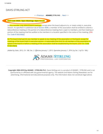
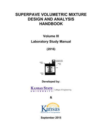
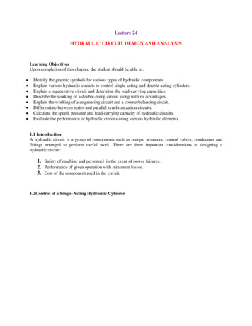
Heat engines use differences in temperatures to produce some form of functional power.The Stirling engine is no different than these engines. Stirling engines run off of simple heatdifferentials and use some working gas to produce a form of functional power. The workinggas undergoes a process called the Stirling Cycle which was founded by a Scottish man namedRobert Stirling. The Stirling Cycle uses isothermal expansion/compression with isochoriccooling/heating. The isochoric means the volume stays the same during the cooling and heatingand the isothermal means the temperature stays the same during the expansion and compression.The Stirling cycle has been found to be highly efficient compared to other heat engine cycleseven with home built model engines. My goal is to achieve a certain efficiency from one ofthese model engines built off of my own designs and own materials. Companies mass producesome kits that home machinists build from but my goal was to see if I could get usable powerfrom creating from a design not taken from a kit.Research:There are three basic types of Stirling heat engines. The Alpha engine is a two cylinderengine with two different pistons. This engine design has been used in a lot of experimentsincluding Solar Power experiments for “green” energy. It has a higher efficiency than the othertwo types of engines so it is typically used more often. The Beta engine has a one cylinder twopiston setup. One piston displaces the working gas and that is called the displacer piston. Theother piston runs like a normal piston causing most of the torque on the flywheel and this iscalled the power piston. The last basic type is called the Gamma engine. This engine is almostidentical to the Beta style but uses two separate cylinders for each piston. There are plenty ofother variations on these basic types but most of the Stirling engine designs all derive from one
of these three basic types.(From left to right Alpha, Beta, Gamma)There are many different ways companies utilize these engines today. Most of them areused purely for research but NASA is using them in satellites that they plan to launch in the nextfew years. NASA will use a free piston design and use radioisotopes to fuel the engines itself.They use this Stirling Convertor for its high efficiency and its low amount of moving mechanicalparts. This allows for it to run a little longer than some of the other engines they have. Thereverse Stirling cycle is being used as a cryogenic cooler for getting down to cryogenictemperatures. Both the forward and backward Stirling cycles are more efficient than most of theother heat engine/heat pump cycles.Efficiency of engines is rated around the power they output based off of the energy putinto the engine. The Carnot efficiency is the ideal efficiency of any heat engine. This cycle hasa theoretical work output equal to the input of the energy. This requires the temperature of thecold reservoir to be at absolute zero which is impossible, the ideal Carnot efficiency thereforebecomes purely theoretical.
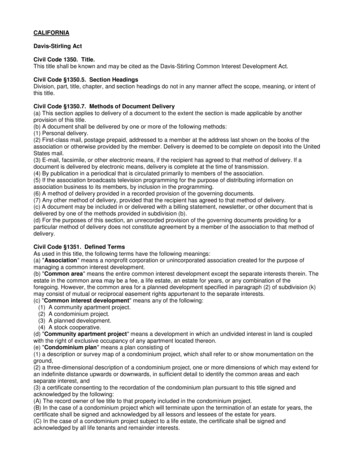
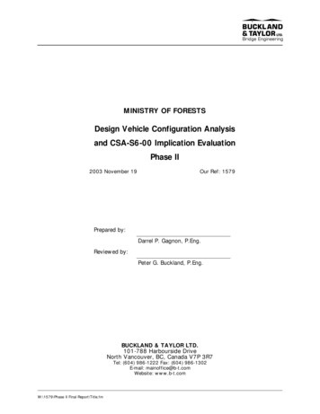
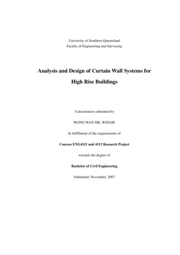
1-2-3-4 PV Process for Stirling/1-5-3-6 Process for CarnotProcess 1-2 shows the isothermal compression of the Stirling engine. Process 3-4 showsan isothermal expansion. Process 4-1 is the isochoric cooling and 2-3 is the isochoric heating.As for the Carnot cycle 1-5 is an isothermal compression, 5-3 is the adiabatic compression, 36 is the isothermal expansion, and 6-1 is adiabatic expansion. The Carnot process allows theenvironment to create the perfect cycle.Carnot EfficiencyStirling Engine WorkThe ideal Stirling efficiency is equal to the ideal Carnot efficiency (proven in mathsection) allowing the Stirling cycle to have the highest hypothetical efficiencies. No internalenergy is lost in the ideal efficiency of the engine because it has a perfect regenerator. TheStirling engine work equation shows that the overall efficiency can be effected by changing thetemperature differences, compression ratios, or working gases. Changing all these variableschanges the work output from the engine causing its efficiency to increase or decrease. Ofcourse the real work is also affected by the mechanical loss in the engine design itself. Thisincludes parts like the regenerator.
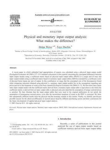
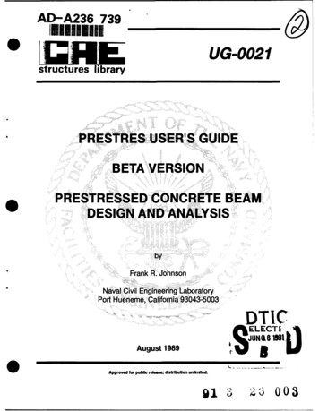
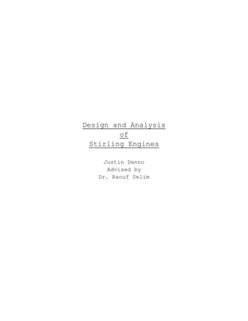
The regenerator also helps the engine achieve its realistic maximum efficiency. Theregenerator limits the amount of thermal energy lost throughout the process done by the workinggas. When the gas passes through the regenerator while its hot the regenerator stays hot. So thenwhen the gas cools down it has to pass through the heated regenerator again thus preheating thegas when it gets to the warm side. This is the opposite for the cold side but the same idea. Thishelps make the engine utilize the energy put in by the heat source more than it would without theregenerator creating more work coming from the engine itself.Design and Build:My design phase began by finding a design or designs that were possible to build withminimal parts or designs that could be easily built in a short amount of time. After this was theactual design phase of each engine that was decided on. After the design phase was the buildphase where an engine would be built based off of the design. This engine would then be runand improved based on run results. The improvements would then be tested until it could not bemade any better.Two designs were decided upon. The first design chosen was a modified Beta designcalled an acoustic design. One of the modifications is that it does not use a displacer piston.This engine performs from the pressure variations caused by the changes in temperatures. Thepressure changes are modeled by the ideal gas law(PV nRT). As the temperature goes upat constant volume the pressure also increases. When the temperature hits its highest markthe piston expands the volume of the working gas. Once the volume is expanded all the waythe temperature drops at that constant volume causing the pressure to decrease. Once thetemperature drops all the way the volume is compressed and the cycle restarts as long as the heat
source is still there.Acoustic DesignThe second engine to be designed was an engine based off of the Alpha style. Thisengine is highly efficient compared to most home built engines as long as it stays airtight. Thisis a challenge for most because air likes to escape through any minute crack because pressuredifferences. This engine runs from the same heat source as the acoustic it just uses a differentdesign to get power from the heat differences.The original design for the acoustic engine was not as efficient as it could be. Theworking parts had a higher frictional coefficient than a possible design. The initial parts were ametal on metal cylinder piston combination. The improved design uses a pyrex to graphitecylinder. The pyrex graphite combination minimizes the mechanical work loss caused byfriction so it increases the work output by the engine. The working gas was designed to be in apyrex test tube with the heat source at one end and the cold side at the other. Pyrex is a goodmaterial to hold heat and not allow it to travel down the material. This is key in increasing thethermal efficiency by keeping the heat from the heat source to travel down the test tubecontaminating the cold “reservoir”.
The regenerator for this engine is steel wool. It can hold heat pretty well so when the hotair passes through it stays warm waiting for it to pass through again. This is good for doing thework that a regenerator is supposed to do. The steel wool was chosen for both engines based onits performance qualities for holding a constant temperature. Although the ideal regenerator usesa criss cross pattern specifically it will be very difficult to insure this happens with the steel woolregenerator.The acoustic engine parts were connected by placing all the parts on a wooden base withmounting brackets for each piece. The flywheel was connected to the drive-shaft of the pistonby a thin carbon rod. The flywheel could also be adjusted to control the compression ratio of theworking fluid and stroke of the piston itself. The piston and cylinder were connected by a metalsheet and some O-rings. The O-rings were also helpful in creating an airtight seal for the testtube/cylinder connection.The Alpha-V style engine was designed around any basic V engine design. It has twopiston-cylinder sets at a 90 degree offset connected to the same flywheel. My theoretical buildfor this engine had brass components for the piston-cylinder since they both had low frictionalinteractions and were pretty light. The connection between the hot and cold air chambers wasgoing to be a thin rubber hose with the regenerator in the middle of this path.The acoustic engine was built based on the designs. This engine never got running frommany different problems addressed in the problems section. The engine was built in a span of afew months. The alpha design never got built because the acoustic engine never got running.Most of the time planned for building the alpha engine got put towards fixing the problems ofthe acoustic engine.
The ideal efficiency of either Stirling engine is .837 using 1800 Kelvins for thetemperature of a candle flame and 293 Kelvins as room temperature. Using a propane torch anideal efficiency is around .87 using a temperature of 2200 Kelvins for the torch. My goal for theacoustic engine was to get to at least a quarter of the ideal efficiency for either scenario. Thetotal efficiency is limited by the problems caused in the machined parts. For example, Pyrexsoftens around 1100K only allowing for an efficiency .73 compared to the .837 ideal. Brasssoftens around 1300K only allowing for an efficiency of .78. These kinds of limitations added tothe problems home built engines would have compared to the ideal Stirling engine creates mylow estimation of getting an efficiency around a quarter of the highest efficiency.Problems:A lot of problems arose trying to get the acoustic flow engine to run based off of theregenerator alone. Finding a good regenerator is pretty expensive and engineering it is verydifficult. Simply shoving steel wool into the working fluid will create more opportunities fordead volume to occur which can stop the working gas from working at all. There were mostlikely a few spaces where dead volume caused a little bit of trouble. The piston also showed anexpansion of volume in the working gas but would never compress. This means that there maybe a potential leakage in the engine itself. Not having the tools necessary to test for air leakskind of hindered my ability to fix where each leak may have been.The highest efficiency for this engine would also need to have Hydrogen or Heliumgas as its working gas. With the air leakage from open air there was no doubt in my mind anypressure change would create a leak for these lighter gases. Also Hydrogen is flammable so anyleak that comes in contact with the fuel source may ignite and cause a lot of problems. My lack
of needed building materials and engineering experience hurt the acoustic engine altogether andcaused a few problems.Conclusion/Further Research:Further research to be done on this project includes actually building and testing theAlpha engine. Further research also includes getting the acoustic engine to actually run and intotesting. After both engines get running both would undergo testing and hopefully improvementsfor both. Since they did not get running the hypothetical power outputs were not able to betested. Efficiency could not be tested at all because of the engine not running. This also meansmy .21 efficiency goal was also not achieved. Eventually I would like to build these engines andget an efficiency of around .4 at least.
Math:W Work; P Pressure; V Volume; n molecules; R Gas constant; T Temperature;Q Heat energy; S Entropy;Substitute for P since T is constant.Th Hot Temp; Tl Low TempV4 V1 and V3 V2 so the work simplifies toUsing the first law of Thermodynamics this becomesdU in this case 0 because there is no energy lost in the internal system based on the ideal regeneratorWhich is the Carnot efficiency which can also be written as
Research Articles:(Although no articles were cited these are the articles that I referred to a lot during my research)1. “Advanced Stirling Convertor”, http://www.grc.nasa.gov/WWW/TECB/rps asc.htm2. “Stirling Engine” by Gaivoronsky Alexander Ivanovich, 4.pdf3. Thermal Physics by Daniel Schroeder; Chapter 4 “Engines and Refrigerators”4. “Stirling Engines-Mechanical Configurations” by Dr. Israel Urieli; http://www.sesusa.org/DrIz/engines/engines.html5. “An Introduction to Stirling Cycle Machines” by David ng Intro.pdf
The acoustic engine parts were connected by placing all the parts on a wooden base with mounting brackets for each piece. The flywheel was connected to the drive-shaft of the piston by a thin carbon rod. The flywheel could also be adjusted to control the compression ratio of the working fluid and stroke of the piston itself. The piston and cylinder were connected by a metal