Transcription
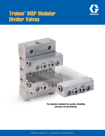
Modular System for Fixation in the Sacrum and IliumUSS II Ilio-SacralSpine System Surgical Technique
Image intensifier controlThis description alone does not provide sufficient background for direct useof DePuy Synthes products. Instruction by a surgeon experienced in handlingthese products is highly recommended.Processing, Reprocessing, Care and MaintenanceFor general guidelines, function control and dismantling of m ulti-partinstruments, as well as processing guidelines for i mplants, please contact yourlocal sales representative or refer are-maintenanceFor general information about reprocessing, care and maintenance of Synthesreusable devices, instrument trays and cases, as well as processing of Synthesnon-sterile implants, please consult the Important Information leaflet(SE 023827) or refer are-maintenance
Table of ContentsIntroductionSurgical TechniqueUSS II Ilio-Sacral Spine System 2AO Spine Principles 4Iliac Fixation with Iliac Connector 5S2 Fixation with S2 Connector 14 Insertion S2 connector left/right 17 Insertion S2 connector for rod end 19Remobilisation of the Polyaxial Connection for Implant Removal 21Indications and Contraindications 22Bibliography 23For product catalog contact your local DePuy Synthes representativeSurgical TechniqueUSS II Ilio-Sacral Spine SystemDePuy Synthes 1
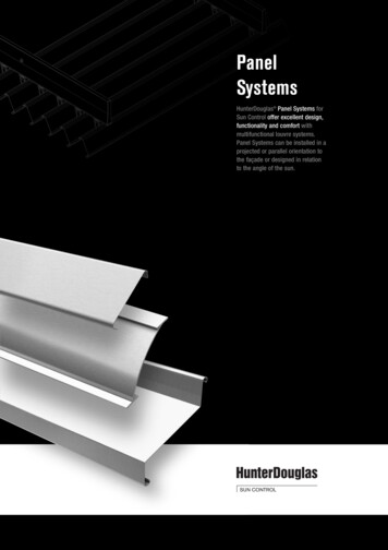
USS II Ilio-Sacral Spine SystemOverviewThe USS II Ilio-Sacral Spine System is intended for additional rod fixation in the ilium and in S2.There are different connectors available for the linkageto the ilium and to the S2 pedicle. All connectors arecombined with the USS II Polyaxial bone screws.USS II Ilio-SacralUSS II nut Add-on to USS II Polyaxial Uses the same bone screws(lengths up to 140 mm)Fixed length iliac connector (1)Telescopic iliac connector (2)21Clamp for fixed length/telescopic iliac connectorColletDual-core cancellous bonescrews6.2S2 connector, left/rightS2 connector, for rod endPelvic connectorsPelvic rodS2 fixation2 DePuy SynthesUSS II Ilio-Sacral Spine SystemSurgical Technique7.08.0
USS II Ilio-Sacral Spine SystemSurgical TechniqueUSS II Ilio-Sacral Spine SystemDePuy Synthes 3
AO Spine PrinciplesThe four principles to be considered as the foundationfor proper spine patient management underpin thedesign and delivery of the Curriculum: Stability –Alignment – Biology – Function.1,2StabilityStabilization to achieve aspecific therapeuticoutcomeAlignmentBalancing the spine inthree dimensionsBiologyEtiology, pathogenesis,neural protection,and tissue healingFunctionPreservations and restoration of function to prevent disabilityCopyright 2012 by AOSpine4 DePuy SynthesUSS II Ilio-Sacral Spine SystemSurgical Technique
Iliac Fixation with Iliac Connector1. Extend construct caudally toinclude S1Instrument the spine with a rod construct down to S1according to the surgical technique of the UniversalSpine System (USS) implants used (e.g. USS II Polyaxial).In S1, it is recommended to use a USS II Polyaxial cancellous bone screw.Note: Leave at least 3 cm excess rod caudally to theS1 screw for later placement of the iliac connector.AlternativeInstead of applying the iliac connectors to the rod as thelast step in the surgery, it is also possible to insert allscrews and iliac connectors first, and then apply the rod.2. Determine size of iliac connectorRequired instruments03.621.031–33 Templates (short, medium, long)Use the templates to determine the proper implant size. Either the telescopic or the fixed-length iliac connectormay be used.Notes: Fixed length connector: The distances indicated onthe template correspond to the implant size (mm). Telescopic connector: The distance varies between17 and 27 mm.Surgical TechniqueUSS II Ilio-Sacral Spine SystemDePuy Synthes 5
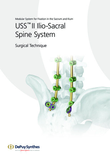
Iliac Fixation with Iliac Connector3. Attach clampRequired instrument03.621.011Clamp HolderPick up the corresponding clamp for the telescopic orfixed-length connector from the tray using the ClampHolder.Note: The Clamp Holder is approx. twice as long asthe USS II Polyaxial Screw Holder.Attach the clamp to the rod from the midline. If necessary, remove excessive bone below the rod to createenough space for the clamp.Clamp for fixed-length iliac connectorClamp for telescopic iliac connectorPrecaution: To prevent possible tissue irritationremove enough bone on the ilium so that the iliacconnector will be seated below the original iliaccrest.6 DePuy SynthesUSS II Ilio-Sacral Spine SystemSurgical Technique
Iliac Fixation with Iliac Connector4. Place iliac connector and createscrew entry pointRequired instrument03.621.011Clamp HolderDrop the iliac connector over the Clamp Holder. Withthe implant in place, verify that the correct implant sizehas been chosen.Use a pedicle probe to drill the screw hole in the centerof the opening of the iliac connector. This ensures thatthe screw will be placed at the correct distance to therod.After drilling the screw hole, remove the iliac connector.Alternative screw placement in the ilium: The screw maybe placed from the inner side of the iliac crest in orderto reduce the extent of soft tissue exposure.Surgical TechniqueUSS II Ilio-Sacral Spine SystemDePuy Synthes 7
Iliac Fixation with Iliac Connector5. Insert bone screwRequired instruments03.607.001Screwdriver, bihexagonal 3.0 mm,with T-Handle03.607.003USS II Polyaxial Holding SleeveOptional instruments03.607.002Screwdriver Shaft for screws 70 mm03.607.006USS II Polyaxial Handle388.622Handle for Screw HolderPick up the appropriate screw from the screw rack usingthe Screwdriver and the Holding Sleeve. Insert the screwinto the prepared ilium until the screw is well seated.Note: For cancellous bone screws with a length of70 mm or longer, use the Screwdriver Shaft03.607.002 a ttached to the USS II Polyaxial Handle.8 DePuy SynthesUSS II Ilio-Sacral Spine SystemSurgical Technique
Iliac Fixation with Iliac Connector6. Expose screw headRequired instruments03.607.000USS II Polyaxial Reamer03.607.001Screwdriver, bihexagonal 3.0 mm,with T-HandlePlace the Reamer guided by the Screwdriver over thescrew head. Ream away excessive bone by moving thereamer back and forth until the red mark on the screwdriver shaft becomes visible.Note: If more bone that may block the connector hasto be removed, use a chisel or gauge pliers.Surgical TechniqueUSS II Ilio-Sacral Spine SystemDePuy Synthes 9
Iliac Fixation with Iliac Connector7. Click on the colletRequired instruments03.607.005USS II Polyaxial Screw Holder03.607.006USS II Polyaxial HandleOptional instruments388.622Handle for Screw HolderUse the USS II Polyaxial Screw Holder to pick up a colletfrom the tray. Optionally, attach the Handle.Click on the collet and orient the notch on the collet indirection of the screw angulation to achieve largerangles. Afterwards release the Handle leaving the ScrewHolder attached to the collet.Precaution: Make sure that no tissue is stuckbetween the screw head and the collet.10 DePuy SynthesUSS II Ilio-Sacral Spine SystemSurgical Technique
Iliac Fixation with Iliac Connector8. Insert iliac connectorRequired instruments03.621.011Clamp HolderAttach the clamp to the rod from the midline.Slide the iliac connector over both the Clamp Holder andthe Screw Holder.Surgical TechniqueUSS II Ilio-Sacral Spine SystemDePuy Synthes 11
Iliac Fixation with Iliac Connector9. Lock iliac connectorRequired instruments03.621.012Socket Wrench, cannulated,with Straight Handle for USS-II Nut388.584Socket Wrench for twelve point nut,with L-Handle388.143Socket Wrench 5.0 mm, with T-HandlePick up a nut using the Socket Wrench with StraightHandle (black), place it over the collet of the iliac screwand tighten it slightly. (1)Notes: Always first place a nut on the collet (iliac screw)and then one on the clamp (rod). Pre-tighten the nut on the iliac screw at least2 revolutions. This is how the iliac connector isfirmly attached to the bone screw while the polyaxiality is still maintained. Pull on the Screw Holderto check if the collet has been attached correctly.Secondly, apply a nut on the clamp, and tighten itslightly. (2)For final tightening, change the Socket Wrench withblack handle to the one with L-Handle. Use the SocketWrench with T-Handle as counter-torque.12 DePuy SynthesUSS II Ilio-Sacral Spine SystemSurgical Technique12
Iliac Fixation with Iliac ConnectorOptional: Lock the clamp of the connector with theSpreader ForcepsRequired instruments388.410Spreader Forceps388.615Support for Rod Introduction Pliers(Clip for Persuader)Precaution: In some cases, the iliac connector maynot be properly seated on the rod, and the nut cannotbe tightened. In this case, use the techniquedescribed below.With the Socket Wrench with L-Handle in place, attachthe Clip for Persuader at the distal end of the ClampHolder. Press the Spreader Forceps. This will pull up theclamp. At the same time, turn the Socket Wrench untilthe nut engages.Surgical TechniqueUSS II Ilio-Sacral Spine SystemDePuy Synthes 13
S2 Fixation with S2 Connector1. Extend construct caudally toinclude S1Place the pedicle screws according to the surgical technique of the USS implant system used (e.g. USS IIPolyaxial)2. Prepare hole for the S2 pediclescrewRequired instruments388.540Pedicle probe Ø 3.8 mmwith Canevasit Handle388.539Pedicle probe Ø 4.8 mmwith Canevasit HandleOpen the pedicle using a pedicle probe.14 DePuy SynthesUSS II Ilio-Sacral Spine SystemSurgical Technique
S2 Fixation with S2 Connector3. Insert S2 screwRequired instruments03.607.001Screwdriver, bihexagonal 3.0 mm,with T-Handle03.607.003USS II Polyaxial Holding SleevePick up the appropriate screw from the screw rack usingthe Screwdriver and the Holding Sleeve. Insert the screwinto the prepared pedicle until the screw is well seated.Ideally, the screw is placed bicortically.4. Expose screw headRequired instruments03.607.001Screwdriver, bihexagonal 3.0 mm,with T-Handle03.607.000USS II Polyaxial ReamerPlace the Reamer guided by the Screwdriver over thescrew head. Ream away excessive bone by moving thereamer back and forth until the red mark on the screwdriver shaft becomes visible.Surgical TechniqueUSS II Ilio-Sacral Spine SystemDePuy Synthes 15
S2 Fixation with S2 Connector5. Click on the colletRequired instruments03.607.005USS II Polyaxial Screw Holder388.622Handle for Screw HolderOptional instruments03.607.006USS II Polyaxial HandleUse the USS II Polyaxial Screw Holder to pick up a colletfrom the tray. Optionally, attach the Handle.Click on the collet and orient the notch on the collet indirection of the screw angulation to achieve largerangles. Afterwards release the Handle leaving the ScrewHolder attached to the collet.Precaution: Make sure that no tissue is stuckbetween the screw head and the collet.Note: Alternatively a USS II Polyaxial 3-D head maybe clicked on the screw instead of using the S2 connector.16 DePuy SynthesUSS II Ilio-Sacral Spine SystemSurgical Technique
S2 Fixation with S2 ConnectorInsertion S2 connector left/right6a. Insert S2 connector (left or right)Required instruments388.584Socket Wrench for twelve point nut,with L-Handle03.607.005USS II Polyaxial Screw HolderSlide the connector over the Screw Holder onto thecollet.Pick up a nut using the Socket Wrench with L-Handle,and place it over the collet of the S2 screw.Pre-tighten the nut on the S2 screw at least two revolutions. This is how the S2 connector is firmly attached tothe bone screw while the polyaxiality is still maintained.Check for a secure seat by pulling on the Screw Holder.Surgical TechniqueUSS II Ilio-Sacral Spine SystemDePuy Synthes 17
S2 Fixation with S2 Connector7a. Insert rod and lock nutsRequired instruments03.607.005USS II Polyaxial Screw Holder388.584Socket Wrench for twelve point nut,with L-Handle388.143Socket Wrench 5.0 mm, with T-Handle03.607.001Screwdriver, bihexagonal 3.0 mm,with T-HandleInsert the rod into the connector.Connect the rod to the remaining screws accordingto the surgical technique of the USS implant systemused (e.g. USS II Polyaxial).Use the Screwdriver to lock the set screw on theS2 connector.Use the Socket Wrench with T-Handle as counter-torquefor final tightening.18 DePuy SynthesUSS II Ilio-Sacral Spine SystemSurgical Technique
S2 Fixation with S2 ConnectorInsertion S2 connector for rod end6b. Insert connector for rod endRequired instrument314.070Screwdriver, hexagonal, small, 2.5 mm,with GrooveInsert contoured rod into the connector and lock the setscrew with the 2.5 mm Screwdriver. Slide the connectorover the Screw Holder onto the collet.Pick up a nut using the Socket Wrench with L-Handleand place it over the collet of the S2 screw.Pre-tighten the nut on the S2 screw at least two revolutions. This is how the S2 connector is firmly attached tothe bone screw while the polyaxiality is still maintained.Check for a secure seat by pulling on the Screw Holder.Surgical TechniqueUSS II Ilio-Sacral Spine SystemDePuy Synthes 19
S2 Fixation with S2 Connector7b. Connect rod to remaining screwsand lock nutsRequired instruments03.607.005USS II Polyaxial Screw Holder388.584Socket Wrench for twelve point nut,with L-Handle388.143Socket Wrench 5.0 mm, with T-HandleConnect the rod to the remaining screws accordingto the surgical technique of the USS implant systemused (e.g. USS II Polyaxial).Use the Socket Wrench with T-Handle as counter-torquefor final tightening.20 DePuy SynthesUSS II Ilio-Sacral Spine SystemSurgical Technique
Remobilisation of the Polyaxial Connectionfor Implant RemovalRequired instruments388.584Socket Wrench for twelve point nut,with L-Handle03.607.005USS II Polyaxial Screw Holder03.607.006USS II Polyaxial HandleOptional instruments388.622Handle for Screw HolderAfter removing the nuts, move the collet back and forthusing the Screw Holder. The collet will come loose.Surgical TechniqueUSS II Ilio-Sacral Spine SystemDePuy Synthes 21
Indications and ContraindicationsPlease refer to the corresponding Instructions for Use forspecific information on Intended use, Indications,Contraindications, Warnings and Precautions, PotentialAdverse Events, Undesirable Side Effects and ResidualRisks. Instructions for Use are available atwww.e-ifu.com and/or www.depuysynthes.com/ifu.22 DePuy SynthesUSS II Ilio-Sacral Spine SystemSurgical Technique
Bibliography1. Aebi M, Thalgott JS, Webb JK (1998): AO ASIFPrinciples in Spine Surgery. Berlin: Springer.2. Aebi M, Arlet V, Webb JK (2007): AOSPINE Manual(2 vols), Stuttgart, New York: Thieme.Surgical TechniqueUSS II Ilio-Sacral Spine SystemDePuy Synthes 23
EMEA 04/21(036.000.791; DSEM/SPN/0115/0262) EOS: 170050-210310All rights reserved. SE 826399 AANot all products are currently available in all markets.This publication is not intended for distribution in the USA.Surgical techniques are available as PDF files atwww.depuysynthes.com/ifu DePuy Synthes Spine, a division of Synthes GmbH. 2021.Synthes GmbHEimattstrasse 34436 OberdorfSwitzerlandTel: 41 61 965 61 11www.jnjmedicaldevices.com
Pick up the corresponding clamp for the telescopic or fixed-length connector from the tray using the Clamp Holder. Note: The Clamp Holder is approx. twice as long as the USS II Polyaxial Screw Holder. Attach the clamp to the rod from the midline. If neces-sary, remove excessive