Transcription
AD-A236 739UG-0021LU-structures libraryPRESTRESi USER'S.GIDaBETA VERSIONPRESTR ESS ED CONCRIETE B:EA*M.DESIGN AND:;; ANALYSISby*SNavalFrank R. JohnsonCivilEngineering Laboratory.Port Hueneme, California 93043-5003OTICELECTEJUNQO 1891.August 1989UApproved for publi reene; distriuton unimed.91 2 3003I
DISCLAIMRThis program is furnished by the Government and is accepted andused by the recipient with the express understanding that the UnitedStates Government makes no warranties, expressed or implied, concerningthe accuracy, completeness, reliability, usability, or suitability forany particular purpose of the information and data contained in *hisprogram or furnished in connection therewith, and the United Statesshall be under no liability whatsoever to any person by reason of anyuse made thereof. The program belongs to the Government. Therefore,the recipient further agrees not to assert any proprietary rightstherein or to represent this program to anyone as other than aGovernment program.00wiii
PREFACEThe purpose of this report is to present technical information.The information contained in this report is technical in nature. Itdoes not represent the policy of the Naval Civil Engineering Laboratory,the Naval Facilities Engineering Command, the Assistant Commander ofEngineering and Design, or the Director of Engineering System Division.It is one of a series designed to provide technical information anddocumentation for studies conducted in support of the Naval FacilitiesEngineering Command Graphics Engineering and Mapping System, EngineeringMicrocomputer Graphics, Computer-Aided Design, Cost Engineering System,and Guide Specifications System as they relate to the Naval FacilitiesSystem and life cycle facilities management.iv
PagoINTRODUCTION . . . . . . . . . . . . . . . . . . . . . . . . . . .1CAPABILITIES .1.SOLUTION METHOD .PROBLEM DATA PREPARATION INSTRUCTIONS .EXECUTION INSTRUCTIONS .1.3.4Installation .Standard Execution .Output Redirection .Batch File Execution .REFERENCES .APPENDIX A-4555.6.Example Problem .A-1Acoesslon lor4wjXTISGRA&IDTIC TABUnannounced0Justificat ioByDistributi onfAvailabiLity CobsDvail nd.aLDistSpeciaL.gjv-
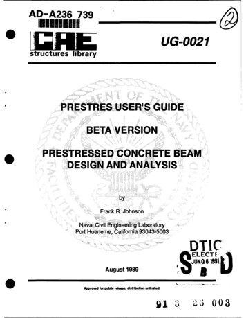
IINRODUCTIONPRESTRES is a prestressed concrete beam design and analysis programfor simply supported beams. The program has been tailored for highwaybridge girders; however, with modifications, it can be used to designpiers and buildings. The American Association of State Highway andTransportation Officials (AASHTO) and the Prestressed Concrete Institute(PCI) standard bridge beams and design procedures are currently used inthe program.CAPABILITIESPRESTRES is a simple beam design program for highway bridgegirders (Ref 1).The beam cross sections are limited to the threeAASHTO-PCI shapes. The loading conditions are limited to the AASHTOstandard truck and lane loading with optional overload conditions(Ref 2). The program computes the compression and tension bendingstress for the extreme fibers of the beam. The prestressing force andmaximum and minimum eccentricity at each of 20 equally spaced sectionsalong the beam are determined. Additional tension and shearreinforcement steel requirements are also determined.SOLUTION METHODpThe AASHTO-PCI standard bridge beams are used in the program.These include the six I-beams, eight box beams, and the eight slabbeams. The cross-section dimensions for these beams are shown in Figure1. The basic section properties for these sections are part of theprogram, so the user does not have to be concerned with these details.The prestressing strands have been arranged for each of the crosssections.The prestressing strand arrangement is based upon geometricconstraints and manufacturing procedures of a typical manufacturin&plant. The clearances between strands and exterior surfaces have beendefined. The bottom-most row is filled with strands before starting anew row. The prestressing force and the eccentricity of the strandgroup centroid with respect to the centroidal axis of the cross sectionare determined without user direction. This information Is placed in atable of prestressing forces and associated eccentricities for eachcross-section type.The girder may be designed to include the effects of compositesection properties. When designed in this manner, the shoring in theactual structure must not be removed until the supported elements havedeveloped the design properties required in the analysis. The effectiveI
depth of the slab, total depth less the wearing surface, and theeffective flange width (AASHTO Section 1.7.99), defined as the minimumof:(1) one-fourth of the beam span length, (2) the center-to-centerdistance between the girders, and (3) twelve times the slab minimumthickness, are used in the computation of the composite sectionproperties.The live and dead load are considered in the selection of themember size. The live load may be selected from any of the standardAASHTO highway loadings:H10-44, H15-44, H20-44, 1S15-44, and HS20-44.The truck and lane loads associated with these designations are shown inFigure 2. A military loading, consisting of two 24-kip loads separatedby 4 feet, or a load factor applied to the HS20-44 load, can be used tocreate heavier loads. The program calculates the effects of thesemoving loads by using superposition.The moment and shear diagrams are computed as the load moves acrossthe structure. Manual methods use the influence diagram (line) concept,which computes the reaction, shear, or bending moment values at oneparticular point along the beam length for a unit concentrated loadmoving across the beam. The method used in the program computes, ateach of 21 equally spaced locations along the length of the beam, themaximum shear and bending moment that occurs as the load moves acrossthe structure. When added to the uniform dead load moment and shearvalues, the maximum moment and shear envelope for the entire length ofthe member is known.AASHTO design factors are applied to the shear and moment values.The impact factor (AASHTO Section 1.2.12) is applied to account fordynamic effects of moving loads. Lateral distribution of wheel loads tointerior beams (AASHTO Section 1.3.1) is considered. Finally, the distribution of the concentrated wheel loads for the standard trucks shownin Figure 2 is accomplished.The moment and shear quantities for the right-hand side of themember are compared to their respective quantities on the left-hand sideof the member. Symmetric moment and shear diagrams are obtained byusing the largest value found at each of the respective equally spacedlocations in the right and left half of the beam.The allowable stress design method is used to select the prestressing force and eccentricity values for the specified service loads.Allowable stress values for flexure are defined for the transfer condition when the prestressing force is transferred from the jacking systemto the beam, and after the prestressing force has reduced due to losses.The flexural stress, composed of the axial prestressing force stress,the prestressing force eccentricity bending stress, and the bendingstress induced by the service load moment, are compared to the allowablestress values. The minimum prestressing force and associated eccentricity are selected when the allowable stress constraints have been satisfied. If the table of prestressing forces is exhausted before the stressconstraints are satisfied, a larger section will be tried.The maximum and minimum eccentricities at each of the 21 equallyspaced locations along the length of the beam are determined. Theallowable stress constraints will be satisfied as long as the centroldof the prestressing strand group is located within these limits. Theselimits can be used to locate hold-down points to cause the prestressing2
strands to be draped so the group centroid will remain within thelimits. The hold-down points are symmetrically located with respect tothe center of the beam.The ultimate moment criteria (AASHTO Sections 1.6.5.E and 1.6.10)are evaluated. The percentage of prestressing steel can be increased ora new section can be tried if this criteria is exceeded.Nonprestresssed tension reinforcement may be required at transfer.This requirement is based upon exceeding allowed tension criteria(AASHTO Section 1.6.7.B.1). The area of steel required to reinforce thetop fibers of the beam during the transfer condition is determined. Thedetailer selects the actual bar size and length.Diagonal tension stress reinforcement or shear reinforcement placedperpendicular to the axis of the member is determined (AASHTO Section1.6.13). The shear reinforcement for the web and additional stirrupsteel required in the end block is determined.Deflection is computed for the dead loads. The deflection thatoccurs at transfer, and the deflection after the placement of the slabis determined.PROBLEM DATA PREPARATION INSTRUCTIONSA prestressed beam may be designed by providing the following data:Line Type A:Column1 - 4041 - 6061 - 72VariableHEADIHEAD2HEAD3Line Type B:DescriptionProject titleProject engineerDateDesign ControlColumnVariableDescription1 - 56 - 1011 - 15NAMBEMDESIGNICOMP16 - 20TENZRO21 - 25INVESTAASHTO section designatorPRE or POST tension design.Design for a beam and slab composite sectionfor one of the following loading conditions:LIVE load, DEAD load, or NO load.Design for zero tension bending stress: YESor NODesign investigation, known prestressingforce and eccentricity: YES or NOLine Ty1e C:pProblem IdentificationGeometryColumnVariableDescription1 - 1011 - 20SPANBSPACEBeam span (ft)Distance between beams (ft)3
21 - 3031 - 4041 - 50TSLABWEARCAMBER51 - 60ADLOADLine Type D:Column1 - 10VariableDescriptionFPCPRSPrestressed concrete compressive strength(ksi)Concrete compressive strength at transfer(ksi)Slab concrete compressive strength (ksi)Prestressing force ratio, the transfer forcedivided by the after losses force usuallyabout 1.11.Reinforcing steel yield strength (ksi)Additional tension and shear reinforcingsteel bar size number.FPCI21 - 3031 - 40FPCSLBALPHA41 - 5051 - 55FPYIBARLine Type E:LoadingVariableDescription1 - 5ITRUCK6 - 10MILLODAASHTO truck loading: HS20, HS15, H20, H15,H10Military lane loading: YES or NO11 - 20LODFACLoad factor to increase HS20 loading.Line Type F:0Concrete and Steel11 - 20ColumnTotal slab depth (in)Wearing surface thickness (in)Additional concrete added to the slab toreduce the effects of camber caused byprestressing (in).Additional uniform dead load (lb/ft)Prestressing Conditions for Design InvestigationColumnVariableDescription1 - 1011 - 20FEKnown prestressing force (lb)Known hold-down point eccentricity (in).EXECUTION INSTRUCTIONSThe program is designed to run on an IBM PC compatible personalcomputer having at least 512K memory and a math coprocessor. There area number of ways to execute these programs, and each will be discussed.InstallationThe PRESTRES program is on a single diskette.contains:The diskette0
PRESTRES.EXEThe executable programTEST.DATThe. example problem (Ref 3) inthe appendixThese files should be copied to the hard disk or to another floppy diskbefore the program is used. The standard DOS COPY Command can be used:COPY A:*.* C:COPY A:*.* B:For the hard diskFor the floppy diskThe program is now ready to run using one of the methods describedbelow.Standard ExecutionPThe standard way of executing the program involves preparing aninput file and running the program with the print output going to afile. The program assumes the input data are contained in the filePRESTRES.DAT. The data can be prepared using any line or screen editorprogram, such as the DOS EDLIN editor. The user should prepare thisfile using the PRESTRES.DAT file name, or the input can be prepared byusing any file name, and then copying the prepared file to PRESTRES.DATby using the standard DOS COPY Command. The program will write theoutput to PRESTRES.OUT. The PRESTRES.OUT file can be printed using thestandard DOS PRINT Command.The program PRESTRES.EXE is executed by typing:PRESTRESOutput RedirectionThe user can use the DOS SET Command to redirect the input andoutput. The default input, output, and plot file names can be changedby:SET PRESTRES.DAT your input file nameSET PRESTRES.OUT your outpuit file nameThen the program can be run by the PRESTRES command. CAUTION! The DOSredirection mechanism is active for the duration of the run of theprogram. The SET Command stays set ,intil the connection is broken inthe following manner or through a system reboot:SET PRESTRES.DAT SET PRESTRES.OUT Batch File ExecutionpThe programs can be run with a batch file. For example, the batchfile might be called RUNPCB.BAT, and it would contain:5
SET PRESTRES. DAT %l. DATSET PRESTRES. OUT LPTIPRESTRESSET PRESTRES.DAT SET PRESTRES. OUT The program would then be executed by the command:RUNPCB your data file name The data file name should be typed without the assumed DAT extension.REFERENCES1. F.R. Johnson. "An interactive design algorithm for prestressedconcrete girders," Computers and Structures, Great Britain, vol 2, Dec1972, pp 1075-1088.2. American Association of State Highway and Transportation Officials.Standard specifications for highway bridges, Ninth Edition, 1965.Washington, DC, 1966.3. H.K. Preston and N.J. Sollenberger.New York, NY., McGraw Hill, 1967.Nodern prestressed concrete,06
111cBEAM CROSS SECT1IS3"-.5P)Ia-.SECTIONSECTIONSECTIONTYPE I BEAMTYPE 11BEAMTYPE III BEAM55 TO 80 FT. SPANS40 TO 60 FT. SPANS30 TO 45 FT. SPANS-6It"Ta.5toc7.5rIlao.to.-. . .Do::::. .o.-472'-2"2'-f2'SECTIONSECTIONTYPE IV BEAM70 TO 100 FT. SPANS.
AASHTO highway loadings: H10-44, H15-44, H20-44, 1S15-44, and HS20-44. The truck and lane loads associated with these designations are shown in Figure 2. A military loading, consisting of two 24-kip loads separated by 4 feet, or a load factor applied to the HS20-44 load, can be used to create heavier loads. The program calculates the effects of these moving loads by using superposition. The .Author: Frank R. JohnsonPublish Year: 1989