Transcription
The first truly integratedmixed zone control systemthat communicates directlyto the Munchkin Boiler.Heat Transfer Products, Inc.120 Braley RoadEast Freetown, MA 02717
USING THIS MANUALUSING THIS MANUALA. INSTALLATION SEQUENCEFollow the installation instructions provided inthis manual in the order shown. The order ofthese instructions has been set in order toprovide the installer with a logical sequence ofsteps that will minimize potential interferencesand maximize safety during heater installation.B. SPECIAL ATTENTION BOXESThroughout this manual you will see thesespecial attention boxes to the right of this pagewhich are intended to supplement theinstructions and make special notice ofpotential hazards. These categories are asdefined by the ANSI Z535.A Standard.DANGERDANGER indicates an imminently hazardoussituation which, if not avoided, will result indeath or serious injury.WARNINGWARNING indicates a potentially hazardoussituation which, if not avoided, could result indeath or serious injury.CAUTIONCAUTION Indicates a potentially hazardoussituation which, if not avoided, may result inminor or moderate injury.CAUTIONCAUTION used without the safety alert symbolindicates a potentially hazardous situation which,if not avoided, may result in property damage.TABLE OF CONTENTSSECTION 1General InformationPg. 3SECTION 2How Vision 2 WorksPg. 3SECTION 3System OperationPg. 3SECTION 4The Vision 2 Control System FeaturesPg. 4SECTION 5Installation of Your Vision 2Pg. 6SECTION 6Vision 2 ProgrammingPg. 10SECTION 7Vision 2 Program AccessPiping Diagrams / Electrical Diagrams2Pg. 11Pgs. 18–24
GENERAL INFORMATION / HOW VISION 2 WORKS / SYSTEM OPERATIONSECTION 1: GENERAL INFORMATIONThe Vision 2 is the first truly integrated mixed zone control system that communicates directly to theboiler through a three wire bus connection. Each Vision 2 can control up to 4 independent zones. MultipleVision 2 control panels can be connected together to control up to 32 independent zones. Visioncontractors can now use a Munchkin Boiler and seamlessly control individual zones operating at differenttemperatures through the Vision 2 controller. Each zone is controlled through a motorized modulating,three way mixing valve that will control the delivered temperature to the zone and the supply temperaturefrom the connected Munchkin Boiler. If two or more zones are calling for heat at the same time, eachthree way mixing valve will automatically adjust to assure that only the required temperature is deliveredto each zone. This feature allows the Munchkin Boiler to operate at a much higher efficiency when hightemperature zones are required. Only Vision contractors can install the Vision 2 system with the use ofa Vision Pass Code. This gives each customer the assurance that the Vision System will be installedproperly and professionally.SECTION 2: HOW VISION 2 WORKSThe Vision 2 control uses a three wire bus communication system to control up to 4 independent zonesand controls the operation of the connected Munchkin Boilers. The Vision 2 control will regulate theoperation of each connected three-way mixing valve to assure you that the desired supply temperatureis achieved. Each three way mixing valve will adjust the flow from the primary loop and return water fromthe zone in order to achieve the desired temperature output to the zone. The Vision 2 panel will thencommunicate with the Munchkin Boiler to regulate its output and temperature set point in order to satisfythe needs of the independent zones. Each mixed zone is equipped with a highly accurate strap-on supplytemperature sensor (spring loaded for better surface connection to the pipe) to assure the most accuratetemperature measurement. The supply temperature sensor is installed on the mixed water outletconnection from the three mixing valves and wired back to the Vision 2 panel. The supply temperaturesensor controls the modulation of the mixing valve and the boiler supply temperature to assure anaccurate temperature response to the mixed zone. Each individual mixed zone can supply additionaltraditionally piped zones that all require the same mixed temperature.Individual zones can be controlled through the use of a thermostat, outdoor sensor, or a 0-10 volt inputfrom a building management system. If an outdoor sensor is used, each independent zone can beprogrammed with a personalized outdoor reset curve.SECTION 3: SYSTEM OPERATIONWhen the Vision 2 is powered, mixed zone 1 is displayed, which is the supply temperature sensortemperature. If the S3 key is pressed, the next consecutive zone temperature will be displayed. The lastfunction displayed is the temperature measurement in Fahrenheit to Celcius. Vision 2 allows the user tocontrol a zone temperature through either an outdoor reset, 0-10 volt input or a thermostat. Once theVision 2 receives a signal for a call for heat, the Vision 2 panel will start to regulate the supply temperatureby modulating the three way valve to meet the desired supply temperature. Individual outdoor resetcurves can be programmed for each of the four mixed zones to the Vision 2 system. Once the roomthermostat or 0-10 volt signal is sent , the Vision 2 panel will integrate the operation of the MunchkinBoiler with the mixed zones to regulate the input into the system to assure maximum efficiency of yourheating system.Note: The Vision 2 may be used with Vision 3 when more than one boiler is used for the heating system.3
SYSTEM OPERATION / INSTALLATIONPARTS INCLUDED IN YOUR VISION 2 SYSTEM1. Outdoor sensor – (1) piece. (7250P-319)2. Indirect Sensor – (1) piece (7250P-325)3. Supply Temperature Sensor (7250P-324) Spring loaded for better surface connection to thepipe) – (1) piece.4. Bus Communication Connection Wire (Line A) - (1) piece.5. Bus Communication Connection Wire (Line B ) - (1) piece.6. Bus Communication Connection Wire (Common) - (1) piece.7. Installation Manual – LP-1188. Warranty – LP-151PARTS INCLUDED IN VISION 2 MIXED ZONE PACKAGE1. “Three Way PWM Motorized Zone Valve (CV-8) – (1) piece. (7250P-479)2. Supply Temperature Sensor (7250P-324) Spring loaded for better surface connection to thepipe) – (1) piece.SECTION 4: VISION 2 CONTROL SYSTEM FEATURESTHERMOSTAT INPUTStandard Room thermostats can be connected directly to the Vision 2 board to control the operation ofthe mixed zones (Maximum of 4 mixed zones for each Vision 2 Panel).OUTDOOR SENSORThe user can install the outdoor sensor directly to Vision 2 board to control the supply temperature tothe mixed zone (a maximum of 4 mixed zones for each Vision 2 Panel). The user can program individual reset curves based on the desired temperature required for that mixed zone.BUILDING MANAGEMENT SYSTEM 0 TO 10 VOLT SIGNAL FUNCTIONBuilding Management systems can connect up to the Vision 2 to change the supply temperature for eachmixed zone (a maximum of 4 mixed zones for each Vision 2 Panel). Each mixed zone can be programmedto allow a 10 volt signal to provide the maximum supply water temperature set point value programmedinto the Vision 2 panel. When the voltage signal to the Vision 2 drops to low as 1.5 volts the supply watertemperature will have reached its lowest programmed setting. If the voltage drops below 1.5 volts, thedemand for heat will shut off. To set your design maximum and minimum temperature, you will need tofirst access the Vision 2 program in Section 7.CAUTIONWiring Connection Specification - Wire 22 AWG Maximum to 100 feet or 18 AWG upto 150 feet. Length of wire cannot exceed 150 feet.4
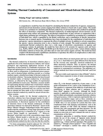
INSTALLATIONFig. 4-124 VAC OUTPUT (LIMITED AMPERAGE 1.0 CAPACITY) FUNCTIONThe Vision 2 is equipped with a 24 VAC output. This can be used to power additional devices that maybe required in the installationSUPPLY TEMPERATURE SENSORThe zone sensor is used to control the heat output from the three-way valve to each mixed zone. The sensor provides an accurate temperature measurement to the Vision 2 board. The sensor is connected witha plastic strap to the A-B section of the three-way valve, assuring fast response to temperature changes.The sensor is equipped with a spring to assure a solid bond to the pipe. Once connected, the sensor willprovide a constant temperature feed back to the Vision 2 board. This assures a very controlled temperature delivery to each mixed zone.110 VOLT PRIMARY CIRCULATOR OUTPUT FUNCTION ( LIMITED 6.3 AMPS MAXIMUM)The Vision 2 can control the operation of each circulator pump connected to the mixed zone. The individual circulator pump for each mixed zone can be wired directly to the panel. This will supply 110 voltsto the mixed pump. The mixed pump will automatically start when there is a call for heat.THREE WAY VALVE OUTPUT FUNCTIONThe Vision 2 can control the modulation of each three way valve connected to the mixed zone. Eachthree-way valve can be connected directly to the Vision 2 panel. Once connected, the three way valvewill modulate the output to a mixed zone to control the supply water temperature. This assures a veryaccurate temperature delivery to each mixed zone.5
INSTALLATION / CONTROL SYSTEM FEATURESTHREE WIRE BUS CONNECTION FUNCTIONThe three wire bus connection allows the Vision 2 board to communicate directly to the connectedMunchkin Boiler. This bus communication is simple to install. Wires are provided that connect the Vision2 to the Munchkin Boiler. Once connected, the Munchkin will only deliver the required supply temperature to the primary loop based on what the individual mixed zone will require during a call for heat.VISION 2 DISPLAY PANELThe Multiple display panel allows the user to monitor and program many functions in the Vision 2 controller .The upper portion of the display, with the push button key, allows the user to activate the different status functions and program the individual mixed zones. The lower section of the multiple displaypanel allows the user to monitor the functions and temperatures for each mixed zone. If the mixed zoneis not being used at the time, the display will read (NC)VISION 2 WITH VISION 1The Vision 1 system can be used to provide an additional priority zone for domestic Hot Water (DHW)see drawing V2-1 in piping details). The additional priority zone provided by the Vision I System for DHWwill now shut down the P1 central heating pump and activate the P2 pump for the DHW. This allows theVision Contractor to provide DHW while still maintaining the four mixed zones of the Vision 2 panel.VISION 2 WITH VISION 3The Vision 3 system can be connected to the Vision 2 when using multiple Munchkin Boilers. The Vision3 will control the operation of the connected Munchkin based on information provided by the Vision 2Control. The three wire bus communication is the only connection needed between the Vision 2 and theVision 3 Control.SECTION 5: INSTALLATION OF YOUR VISION 2MOUNTING THE VISION 2 CONTROLLERSelect a mounting location for the Vision 2 Controller that meets the following criteria: Close to the Munchkin Boiler Dry, relatively clean area Easily accessible for service person Facilitates wiring of the unit Mounting surface must be secure. Location must be within one hundred and fifty feet of all sensors (Outdoor, supply temperature sensor )Remove the cover of the unit by removing each of the four Philips head screws in each corner of theenclosure. Next, slide the cover straight off of the rear part of the enclosure. Position the unit on themounting surface so that the wiring can be accomplished with a minimal amount of difficulty and theLED indicators on the bottom of the unit can be seen by service personnel. Mark the location of themounting holes on the mounting surface. Remove the unit from the area and drill the appropriate sizepilot hole for the mounting screws.CAUTIONDo not drill through the enclosure into the mounting surface. Doing so may causechips to get into the Vision 2 and permanently damage the unit.6
CONTROL SYSTEM FEATURESMount the unit by installing a screw through each of the four holes provided in the rear of the unit. Besure that the unit is securely fastened to the mounting surface.Replace the cover on the unit after all wiring is complete.WIRING POWER TO THE UNITWARNINGWiring of this product should only be done by a qualified, licensed electrician inaccordance with all local wiring codes.Refer to Drawing V2/V3-E1 on page 23 for example wiring.This unit should be supplied with 120 volt power from a branch circuit capable of delivering the necessary current for the system. This unit will draw a maximum of 26.2 amperes in operation with amp drawdependent on the horsepower of the motors attached to it (pumps, three-way valves). Before connecting the supply to the unit, the total required amperage should be calculated by adding the full load ampererating of all the motors together then adding 1 ampere for the control itself. It is suitable and recommended to connect this unit to the same circuit as the Munchkin boiler being controlled as long as thetotal does not exceed that of the supply circuit.The Vision 2 Controller and the Munchkin Boiler must share the same earth ground to guarantee troublefree communications between the Vision 2 Controller and the Munchkin Boiler. This ground connectionshould be made with minimum of 14 AWG wire connected to terminal C1-6 of the Vision 2 Controller andat least one of the ground wires from the Munchkin Boiler as well as a junction box ground connection.WIRING OF MIXED ZONE PUMPSDepending on your installation requirements, mixed zone pumps can be connected directly to the Vision2 Control panel. Listed in the chart below are the Terminal Locations for up to 4 mixed zone pumps.CIRCULATOR PUMPSDevicePump Mixed Zone 1Pump Mixed Zone 2Pump Mixed Zone 3Pump Mixed Zone 4TerminalDescriptionC1-9HotC1-10NeutralC1-2Ground (bare or green)C1-11HotC1-12NeutralC1-3Ground (bare or green)C1-13HotC1-14NeutralC1-4Ground (bare or green)C1-15HotC1-16NeutralC1-5Ground (bare or green)7
CONTROL SYSTEM FEATURESWIRING THE THREE WAY MODULATING VALVEDepending on your installation requirements, three-way modulating zone valves can be connected directly to the Vision 2 Control. Listed in the chart below are the Terminal Location for up to 4 three-way modulating valves.3-WAY MODULATING VALVEDeviceTerminalDescription3-way Zone mmonC2-3Left3-way Zone 23-way Zone 33-way Zone 4WIRING OF SENSORS AND CONTROLS TO THE UNITDepending on the installation, there may be any combination of the following low voltage devicesconnected to the Vision 2 Controller. These devices feed information to the controller from the necessarysources. The Vision contractor doing the installation should be consulted to find out which of thesedevices are used and their location(s).WIRING THE THERMOSTATIf a room or area thermostat is used, it may be connected to the Vision 2 Control by using standard twoconductor thermostat wire. Up to four separate thermostat inputs can be connected directly to the Vision2 panel to control four mixed zones. Listed in the chart below are the four possible room thermostat terminal location.THERMOSTAT TERMINAL LOCATIONDeviceTerminalDescriptionThermostat 3-9LeadC3-10LeadThermostat 2Thermostat 3Thermostat 48
CONTROL SYSTEM FEATURESWIRING OUTDOOR SENSOR, SUPPLY TEMPERATURE SENSORThe Sensors will be connected directly to the Vision 2 Controller using a minimum of 22 AWG wire if therun is less than one hundred feet and a minimum of 18 AWG wire if the run is greater than one hundredfeet but less than one hundred and fifty feet. The total length of wire for these sensors is not to exceedone hundred and fifty feet for each sensor. Connect each sensor lead to the proper terminal on the Vision2 controller see the terminal chart listed below.OUTDOOR SENSOR/SUPPLY TEMPERATURE SENSORDeviceTerminalOutside SensorC4-9C4-10Indirect Sensor or IndirectAquastat Zone 1C4-1C4-2Supply Temp Sensor Zone 2C4-3C4-4Supply Temp Sensor Zone 3C4-5C4-6Supply Temp Sensor Zone 4C4-7C4-80-10 VOLT CONTROL WIRINGIf an energy management system is to be interfaced to the Vision 2 controller, it should be connected withthree conductor thermostat wire. The thermostat wire should be of at least 22 AWG. The positive leadshould be connected to terminal C4-11, the negative lead to terminal C4-12 and the common lead to terminal C4-16. If shielded wire is used, it should be securely grounded at one end of the cable only. It ispreferable to connect the shielded wire at the Boiler Ground Bus.WIRING THE THREE WIRE COMMUNICATION BUSLocate the wires for the communication Bus connection enclosed in the Vision 2 box. You will notice thatthe wires are assembled in a set of three. One pair of wires will be installed into the Munchkin Boiler thatwill communicate with the Vision 2 Controller.WARNINGBe sure the power to the Munchkin boilers is turned off at the supply source before continuingwith the steps below. Serious injury or death could occur if this step is not followed.Using the diagram in Figure 7-3 in section 7 of this manual for reference, insert the black wire with bluestripe into terminal X4-11 on Munchkin Boiler. Insert the red wire with blue stripe into terminal X4-1 onthe Munchkin Boiler. Insert the green wire with the blue stripe into terminal X8-6 for the bus common.Each connection should be checked by simply pulling on wiring to assure proper connection in the X4connector. Route the wires along with the other wires in the boiler and through the hole in the cabinetinto the 4 inch square junction box on the side of the boiler. Wire the communication bus wires directly from the Munchkin Boiler to the Vision 2 Control panel using three conductor thermostat wire of at least22 AWG. The wiring path should be planned to be as short as possible between Munchkin Boiler and theVision 2 Control Panel. If using shielded cable, connect each colored lead to the Vision 2 panel.9
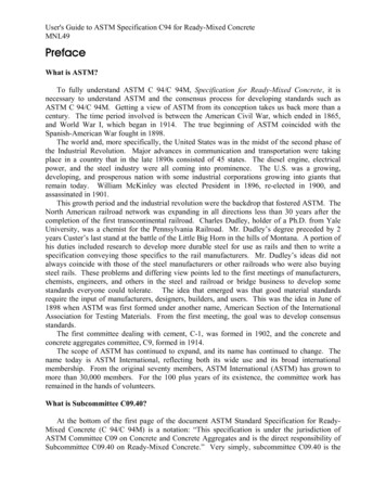
CONTROL SYSTEM FEATURES / PROGRAMMING / PROGRAM ACCESSWIRING MULTIPLE VISION 2 PANELS AND CONNECTION TO VISION 3If multiple Vision 2 panels are used or Vision 3 is used, connect the bus wires in parallel directly from terminal C4-13, C4-14 and C4-15 on the Vision 2 to terminal strip C4-13, C4-14 and C4-15 on the Vision 3or to the next Vision 2. Refer to drawing V2/V3-E1 for an example showing Munchkin Boiler connectedto both the Vision 2 and Vision 3 panel.Fig. 5-1SECTION 6: VISION 2 PROGRAMMINGThe Vision Dealer is the only one qualified to set the system limits and program the outdoor reset curvefor each of the mixed zones on the Vision 2 Controller. These system limits cannot be changed once theyare programmed, by anyone except an authorized Vision Dealer. The owner can only make adjustmentsto the Central Heating Set Point for each mixed zone.Programming the Vision 2 Controller is quite simple. It is recommended that you write down the settingson the control program reference chart provided in this Section 7, Figure 7-1 for future reference. All thefeatures functions can be programmed right from the display located with your Vision 2 system.PROGRAMMING VISION 2 BUS ADDRESSIt is important when using more than one Vision 2 panel that a Busaddress be selected through selection of certain dip switches whichwill give each Vision 2 Controller a unique address thus avoiding communication errors in the system. On the right is a chart which showshow to select the possible address through the dip switch for up toeight Vision 2 Control Panels.10
PROGRAM ACCESSSECTION 7: VISION 2 PROGRAM ACCESSCAUTIONThe Vision 2 cannot be programmed while there is still a call for heat! Make sure allthermostats are turned down. It is important to note that the boiler setpoint must beequal to or set to a higher value than the design supply water temperatureprogrammed into your Vision 2 for each zone. Differential adjustment on the boilershould be co
thermostat or 0-10 volt signal is sent , the Vision 2 panel will integrate the operation of the Munchkin Boiler with the mixed zones to regulate the input into the system to assure maximum efficiency of your heating system. Note: The Vision 2 may be used with Vision 3 when more than one boiler is used for the heating