Transcription
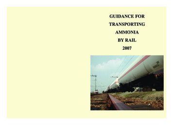
GUIDANCE FORTRANSPORTINGAMMONIABY RAIL2007
GUIDANCE FORTRANSPORTINGAMMONIABY RAILSECOND EDITION(First Edition 2005)Copyright 2007 EFMAEFMAEuropean Fertilizer ManufacturersAssociationAvenue E. van Nieuwenhuyse 4B-1160 BrusselsBelgium
CONTENTS1. INTRODUCTION62. PROPERTIES AND CLASSIFICATION OF AMMONIA2.1General Characteristics2.2Physical Properties of Ammonia2.3Chemical Properties of Ammonia2.4Health Hazards of Ammonia2.5Fire Hazard2.6Stress Corrosion Cracking2.7Classification and Proper Shipping Names67881010113. DESIGN AND CONSTRUCTION OF RAILWAY TANK CARS (RTCS)3.1Application and Regulations3.2Design of RTCs3.3Materials of Construction3.4RTC Valves, Fittings and Couplings3.4.1 Valves and Fittings3.4.2 Couplings3.5Initial Testing of RTCs131415161620214. DANGEROUS GOODS MARKING AND LABELLING4.1Dangerous Goods Identification4.2Warning Plates4.3Substance Name and Maximum Load Identification2325255. RECOMMENDATIONS FOR CONTRACTING ANDMAINTENANCE OF RTCS5.1Contracting RTCs5.2Maintenance Responsibilities5.3Periodic Testing5.4Purging with Nitrogen282829292
6. PERSONAL PROTECTIVE CLOTHING AND SAFETY EQUIPMENT307. LOADING AND UNLOADING OPERATIONS7.1Requirements for Loading and Unloading7.1.1 Recommendations for the Loading/Unloading Area7.1.2 Equipment for the Loading/Unloading Station7.1.3 Loading/Unloading Arm7.1.4 Earthing7.1.5 Emergency Equipment7.2Operator Training and Safety7.2.1 Operator Training7.2.2 Operating Instructions7.2.3 Operator Safety7.3Loading Operation7.3.1 Checklists7.3.2 Suitability of the RTC7.3.3 Purging7.3.4 Filling Weight and Overfilling7.3.5 Checks and Actions Before Loading7.3.6 Checks and Actions During Loading7.3.7 Checks and Actions After Loading7.4Unloading Operation7.4.1 Checks and Actions Before Unloading7.4.2 Checks and Actions During Unloading7.4.3 Checks and Actions After 2423
8. TRANSPORTATION8.1Safety Responsibilities8.2Obligations of the main participants8.2.1 Consignor8.2.2 Carrier8.2.3 Consignee8.3Obligations of the Other Participants8.3.1 Filler8.3.2 Operator8.3.3 Railway infrastructure manager8.4Safe Transport of Ammonia by RTCs8.4.1 General8.4.2 Safe Transport of Ammonia by RTCs4344444445454546464646479. AUDITS9.1Safety and Quality Assessment Scheme9.2Internal Audits474810. EMERGENCY RESPONSE10.1 Behaviour of Ammonia on Loss of Containment10.2 Protection of the Surrounding Communities10.3 Limiting the Release10.4 Limiting the Vaporisation10.5 Dissolving Ammonia in Water10.6 Lowering the Concentration of Ammonia Gas/Vapour in Air10.7 Fire Fighting Measures10.8 Emergency Measures10.9 Additional Information on Emergency Response10.9.1 Emergency Plan at Loading/Unloading Sites10.9.2 System of Reciprocal Assistance in Transport Emergencies10.10 Incident Information Sharing10.10.1 Rapid Alert System10.10.2 Accident fact sheets48494950505050515151525353534
11. QUESTIONS AND ANSWERS5312. REFERENCES56ANNEX 1Ammonia Rail Transport Accident Analyses57ANNEX 2Abbreviations60ANNEX 3Nomograph to show some properties of Ammonia61ANNEX 4Methods used to mitigate the consequences of a loss of containment62ANNEX 5Example of a checklist67ANNEX 6Glossary of terms used68ANNEX 7Special checking requirements before and after the filling ofclass 2 products (e.g. ammonia) referred to in RID 4.3.3.4.71DisclaimerThis publication has been prepared by the member companies of the European FertilizerManufacturers Association (EFMA). Neither the Association, any individual membercompany nor any individual representative of the member company can accept liability foraccident or loss attributable to use of the information given in this Booklet. Users of thisBooklet are advised to consult the latest national and international regulations as these mayhave changed since its publication.5
1. INTRODUCTIONThis Guidance for the transport and handling of ammonia has been drawn up by theEuropean Fertilizer Manufacturers Association (EFMA), with the help and expertise ofmembers in order to ensure high safety standards in operations involving ammoniatransport. The Guidance deals exclusively with the transport of anhydrous ammonia in railtank cars (RTC).The importance of ammonia rail transport for the European fertilizer and chemicalproducers is considerable. Every year more than 1,500,000 tonnes of ammonia aretransported in Western Europe by rail. Ammonia is toxic and therefore a number of safetyprecautions are taken to ensure that the relevant operations are carried out safely.EFMA has analysed ammonia rail transport accidents in Europe to get a clearunderstanding of their causes and consequences. This analysis showed that none of theaccidents, injuries or casualties was due to the release of ammonia (see Annex 1). Thepurpose of this Guidance is to improve further the safe handling and transport of anhydrousammonia throughout the European Union as part of EFMA’s Product Stewardshipprogramme [Ref. 12].The transport of ammonia is subject to stringent national and international regulations[Ref. 1-4]. The recommendations made in this Guidance go beyond the requirements ofthese rules and it is recommended that all those involved in the handling and transport ofammonia adopt them as appropriate. Every user of this Guidance is advised to give dueconsideration to the specific circumstances of their installation and situation when applyingthis Guidance. No part of the Guidance should be applied or interpreted in such a way thatconflicts with existing national and/or international regulations. In all cases, such legalrequirements must always take precedence over any part of the Guidance.This 2007 booklet is an updated version of the 2005 booklet. The updated text mainlyrelates to a revision of the RID [Ref 2].2. PROPERTIES AND CLASSIFICATION OF AMMONIA2.1 General CharacteristicsChemical formula:NH3Chemical name:Ammonia, Anhydrous AmmoniaUN Number:1005CAS Number:7664-41-7Molecular weight:17.03At ambient temperature and atmospheric pressure, ammonia is an alkaline, colourlessgas with a pungent and suffocating odour. Ammonia gas is very soluble in water. The gasis strongly irritant/corrosive to the skin, eyes and respiratory tract and has toxic properties.Ammonia gas condenses into a colourless liquid when cooled and compressed. The liquidcan cause severe cold burns on contact with the skin.6
2.2 Physical Properties of AmmoniaTable 1 [Ref 5.] summarises a number of common physical data.Table 1PHYSICAL llPungentPungent3Density (0 C, 101.3 kPa)638.6 kg/m0.7714 kg/m3Density (-33.43 C, 101.3 kPa)682 kg/m30.888 kg/m3Boiling point (101.3 kPa)-33.43 CMelting point-77.71 CCritical temperature132.4 CCritical pressure11.28 Mpa.Critical viscosity23.90 x 10-3 mPa.sSpecific Heat (10 C, 1 MPa)4.67 x kJ/kg KSpecific Heat (-33.4 C, 1MPa)4.47 x kJ/kg KHeat of Vaporisation (101.3 kPa)1370 k J/kgHeat of Solution (1:1 mol H2O, 0 C)30.69 kJ/mol NH3The temperature dependence of some of the properties is given in the nomograph inAnnex 3 [Ref. 10].Table 2 gives the effect of temperature on the solubility of ammonia in water [Ref. 13].Table 2SOLUBILITY OF AMMONIATemperature CSolubility in water, wt% NH31040.02034.23028.54023.75018.5It is important to note that when ammonia is absorbed in water without cooling, thesolubility is limited to about 18% due to the temperature rise of the solution as a result ofthe vigorous exothermic reaction.7
Table 3 summarises the change in density of liquid ammonia with temperature. [Ref.13]Table 3DENSITY OF LIQUID AMMONIATemperature CDensity of Liquid Ammonia, 5705402.3 Chemical Properties of AmmoniaAmmonia is an alkaline gas. The pH of a 1% aqueous solution is approximately 11.7.Ammonia in contact with certain other chemicals including mercury, chlorine, iodine,bromine, calcium, silver oxide or hypochlorites can form explosive compounds.Gaseous ammonia can react violently with nitrogen oxides and strong acids.Ammonia is very corrosive to copper and copper containing alloys and therefore,equipment in contact with ammonia must be free of them.2.4 Health Hazards of AmmoniaAmmonia is a potentially hazardous substance, although it occurs naturally as a result ofmany biological processes. It can produce acute effects on humans and animals. It hasstrong alkaline and hygroscopic properties, which cause a primary irritation or corrosion todamp tissue surfaces, such as the eyes, respiratory system and skin.Ammonia has a pungent odour; the odour threshold of ammonia is in the region of5 ppm. Concentrations between 20-50 ppm in air are detectable by most people. Thisprovides an adequate warning of its presence well below the hazardous concentrationlevels.Gaseous ammonia affects the mucous membranes and the respiratory tract and severelyirritates the eyes. Inhaling high concentrations may cause pulmonary oedema. High gasconcentrations in the air may also cause blisters and chemical burns to the skin. The effectsof exposure to various vapour concentrations are summarised in Table 4 [Ref. 14].8
Table 4EFFECT OF EXPOSURE TO AMMONIAVapourConcentrationppm v/vGeneral effectExposure period5Odour detectableby some people.–25–Occupational exposure standard –long term, 8hr/TWA(MAC value in many countries).35–Occupational exposure standard –short term, 15 min/TWA.50-100Irritation detectableby most people.Tolerable for people unaccustomedto exposure for up to 2 hours. Peopleaccustomed to exposure can tolerate higherconcentrations over the same period.400-700Immediate eye, noseand throat irritation.1 2-1 hr exposure causes no serious damagealthough upper respiratory tract irritationmay persist for 24 hr following 30 minexposure.Aggravation of existing respiratoryproblems could occur.1000-2000Severe coughing,severe eye, nose andthroat irritation.Damage to eyes and respiratory systemcould result in minutes if not treatedquickly. 30 min exposure could producevery serious effects in people predisposedto severe respiratory problems.3000-4000Severe coughing,severe eye, nose andthroat irritation.Could be fatal after 30 min. EstimatedLC50 (derived from animal data) for 2 hrexposure in this region.5000-12000Respiratory spasm.Rapid asphyxia.Fatal within minutes.Estimated LC50 (derived from animal data)for 30 min exposure in this region.Liquid ammonia in direct contact with the skin freezes tissues on contact and causeschemical burns.Threshold Limit Values.The EU threshold values are:TLV/15 min TWA: 50 ppm 36 mg/m3TLV/8 hr TWA:20 ppm 14 mg/m3Note: Threshold Limit Values and terminology differ in different countries.9
2.5 Fire HazardAmmonia gas is combustible, but it is very difficult to ignite. Experiments as well asobservations during accidents have shown that in the case of a release of ammonia in theopen air, the ammonia – air mixture is generally outside the flammability limits [Table 5,Ref. 5]. Therefore the risk of a fire or explosion from an ammonia – air mixture outsidebuildings tends to be negligible. On the other hand, in confined spaces, the situation can bedifferent and the risk of explosion should not be ignored.Table 5EXPLOSIVE LIMITS OF AMMONIAExplosive limits in air (0 C, 101.3 kPa)Minimum auto ignition temperature to DIN 5174916 – 27 vol% NH3651 CIn EU and UN legislation ammonia is not classified as a flammable gas. (Note: in theGlobal Harmonization System it will be classified as category 2: flammable gas).The auto-ignition temperature of ammonia in contact with hot steel is about 650 C.The minimum ignition energy by spark is 680 MJ and 10,000 times higher than theignition energy of hydrogen and 1000 times higher than for natural gas.2.6 Stress Corrosion CrackingStress corrosion cracking (SCC) is a phenomenon which can occur in metals exposed to acombination of stress and corrosive environment.Liquid ammonia in the presence of oxygen can cause SCC in carbon steels.The potential problem of SCC increases with increasing yield strength of the platematerial, increasing strength of the weld metal and the local hardness in the welds.The stress levels required to initiate SCC are high and are not experienced duringnormal operation. However residual welding stress levels together with the applied stresscan be enough to initiate SCC if oxygen is present in sufficient quantities.Ammonia as produced contains no oxygen, but air can get in when it is being transferredfrom manufacturer to user.Tanks for transporting liquid ammonia can be susceptible to stress corrosion cracking ifoxygen is present in sufficient quantity. Therefore the ingress of air into the tank must beprevented and tanks must be purged with nitrogen when commissioned for ammoniatransport.The Institute for Energy Technology, Kjeller, Norway [Ref. 15] carried out an extensiveresearch programme on stress corrosion cracking, sponsored by several European ammoniaproducers. The results of their research show that the presence of water inhibits theformation and the growth of SCC.Figure 1 shows the susceptibility of carbon-manganese steel to SCC in ammonia withdifferent oxygen and water contents at a uniform temperature of 18 C.10
Figure 1 The effect of Oxygen and Water on Stress Corrosion Cracking of Mild Steelin Liquid and Vaporous Ammonia [Ref. 15]The full drawn line in the graph represents the borderline for SCC in these experiments.Above this line no SCC was detected in the experiments.Therefore it is recommended to add at least 0.1% wt water to the liquid ammonia beforetransport.If a customer insists on receiving ammonia without water addition, take special care toensure that the tank of the rail tank car (RTC) is free of traces of oxygen.2.7 Classification and Proper Shipping NameIn the UN classification system for transport, anhydrous ammonia and strong solutions ofammonia are classified as toxic gas of Division 2.3, falling in Class 2.Dilute solutions fall in Class 8, corrosive substances. Table 6 summarises the relevantparticulars.The UN transport regulations specify a proper shipping name for all dangeroussubstances. This also applies to mixtures and solutions. The proper shipping name to be11
filled in on documents is the name in capital letters in the column “Name and description”as shown in Table 6 below.For ammonia and ammonia solutions the following entries apply [Ref. 2]:Table 6UN TRANSPORT CLASSIFICATION AND LABELLINGUNno.Name and ardidentificationnumber1005AMMONIA,ANHYDROUS22.3 8( 13)PxBH(M)12683318AMMONIA SOLUTION,relative density less than0.880 at 15 C in water,with more than 50%ammonia22.3 8( 13)PxBH(M)12682073AMMONIA SOLUTION,relative density less than0.880 at 15 C in water,with more than 35% butnot more than 50%ammonia22.2( 13)PxBN(M)3202672AMMONIA SOLUTION,relative density between0.880 and 0.957 at 15 Cin water, with more than10% but not more than35% ammonia88L4BN380Note:For the UN number 2073 the test pressure and the mass of contents are different for 35-40% and 40-50%solutions.For UN 3318 the test pressure and the mass of contents have to be calculated based on the concentration andpartial pressure at 55 C for tanks with thermal insulation, or 65 C without thermal insulation.All requirements for UN 1005 and 3318 are the same except the test pressure and mass of contents. This meansthat even when the ammonia product contains a few percent water it can be treated as AMMONIAANHYDROUS. (for ammonia the partial pressure is the highest and the density the lowest).Ammonia without any water and ammonia with water (typically up to 0.5%) are bothclassified as UN 1005:AMMONIA, ANHYDROUS;AMMONIAK, WASSERFREI;AMMONIAC ANHYDRE;AMMONIAK, WATERVRIJ.12
3. DESIGN AND CONSTRUCTION OF RAILWAY TANK CARS3.1 Application and RegulationsRailway Tank Cars (RTCs) for transporting anhydrous ammonia must meet therequirements of the following regulations with regard to their design and construction: Any national provisions or the regulations of the respective railway company fornational transportation; Any international provisions, such as the Regulations concerning the InternationalCarriage of Dangerous Goods by Rail (RID) for international transportation.It is important that the most recent versions of the relevant regulations are consultedbefore the design and construction of RTCs is undertaken.The design, materials and construction should be selected to minimise the potential forstress corrosion cracking. As described in Section 2.6 the risk of SCC increases withincreasing yield strength of the plate material, increasing strength of the weld metal and thelocal hardness in the welds. These factors should be taken into account.The required type of tank is given in code form in the RID regulations. Anhydrousammonia has been allocated a tank code of PxBH with special provisions TM6, TT8 andTE 25.P RTC for liquefied gases or gases dissolved under pressure.x value of the relevant minimum test pressure in bar according to the table in RID4.3.3.2.5.B RTC with bottom filling or discharge openings with 3 closures.H hermetically closed RTC. (See RID 1.2.1 or Annex 6 for the definition ofhermetically closed).TM6: RTCs intended for the carriage of liquefied or refrigerated liquefied gases shallbe marked with an unbroken orange band, about 30 cm wide, encircling the shell atmid-height.TT8: RTCs approved for the carriage of UN 1005 AMMONIA, ANHYDROUS andconstructed of fine-grained steel with a yield strength of more than 400 N/mm2 inaccordance with the material standard, shall be subjected to magnetic particle inspectionsto detect surface cracking at each periodic test according to RID 6.8.4.For the lower part of each shell at least 20% of the length of each circumferential andlongitudinal weld shall be inspected, together with all nozzle welds and any repair orground areas.TE25: Shells of tank-wagons shall also be protected against overriding of buffers andderailment or, failing that, to limit damage when buffers override, by at least one of thefollowing measures:1) Measures to avoid overriding. This is done by having installed a device locatedabove every buffer to protect against the overriding of buffers.13
2)3)4)Measures to limit damage when buffers override. This can be done by increasingthe wall thickness of the tank ends or using other material with a greater energyabsorption capacity.Sandwich cover for tanks covering the entire area of the tank ends and with aspecific energy absorption of at least 22 kJ.Protective shield at each end of the wagon.3.2 Design of RTCsThe holding volumes of RTCs commonly used are 50 to 110 m3.Shells shall be designed and constructed in accordance with the requirements of atechnical code recognised by the competent authority, in which the material is chosen andthe wall thickness determined by taking into account the maximum and minimum fillingand working temperatures.Shells, their service and structural equipment, shall be designed to withstand thefollowing without loss of contents: static and dynamic stresses in normal conditions of carriage prescribed minimum stresses at the test pressure as defined in the RID 6.8.2.1.15.Figure 2 Typical example of an ammonia RTC showing the orange band, heat shieldand identification plateRTCs should be constructed with a support framework (under frame) between the twowheel bogies. EFMA recommends that RTCs in which the tank constitutes a selfsupporting member should not be used for the transportation of ammonia.14
More special provisions for ammonia tank wagons have come into force from the 1st ofJanuary 2007. These concern measures to prevent the overriding of buffers and protectionof tank ends (for details see TE25 and RID 1.6.3.27a).Measures should be taken (See RID 6.8.2.1.7.) to protect the shells against the risk ofdeformation as a result of a negative internal pressure (vacuum). These measures includethe choice of materials for the shells and the calculation of the wall thickness of the shell(RID chapter 6.8.2). RTCs should fulfil all the requirements of the RID regulations or theregulations that were applicable at the time of construction.Any thermal insulation applied to the tank should consist of either: a sun shield covering not less than the upper third but not more than the upper half ofthe tank surface and separated from the shell by an air space at least 4 cm across; or a complete cladding of insulating materials, of adequate thickness.The competent authority or a body designated by that authority shall issue a certificatefor each type of RTC attesting that the prototype including fastenings, which it hasinspected, is suitable for the intended purpose and meets the construction and equipmentrequirements of the RID regulations and the special conditions specified for the classes ofsubstances carried. (RID 6.8.2.3.1)Based on the design of the tank (see 3.2) it is possible to fit the tank with or without asafety valve. It is common practice and recommended to design the RTC in such a way thatno safety valves are used.A safety valve, if used, must be in conjunction with a bursting disc. This is part of thetank code PxBH (H: hermetically closed).If RTCs are fitted with safety valves, a bursting disc shall be placed before the valves.The arrangement of the bursting disc and safety valve shall be such as to satisfy thecompetent authority. A pressure gauge or another suitable indicator shall be provided in thespace between the bursting disc and the safety valve, to enable the detection of any rupture,perforation or leakage of the disc which may disrupt the action of the safety valve (seeRID 6.8.2.2.10).3.3 Materials of ConstructionMaterials of tank construction, including the coatings, valves, fittings, gaskets, etc. shallbe suitable for anhydrous ammonia and shall fulfil all the requirements of the RIDregulations and all national regulations when applicable.All the materials, including those of components, which are in contact with theammonia, shall be free from substances liable to react dangerously with it; to formdangerous compounds; to degrade the material properties; or to affect the quality of theammonia.In particular, copper or copper containing materials must not be used.Shells shall be made of suitable metallic materials which shall be resistant to brittlefracture and to stress corrosion cracking between -20 C and 50 C. (RID 6.8.2.1.8)15
3.4 RTC Valves, Fittings and Couplings3.4.1 Valves and fittings3.4.1.1 General descriptionTanks have to be equipped with internal valves and typically with loading/unloadingconnections positioned on both sides of the tank.The number of pieces of equipment on the RTC must be kept to a minimum.Figures 3 and 4 show a typical arrangement of a RTC for carrying anhydrous ammonia.Figure 5 shows an explanatory model of a typical arrangement of hydraulically operatedbottom valves. Figures 6 and 7 show diagrams of a typical hydraulic bottom valve and amechanical bottom valve respectively.3.4.1.2 More detailed information from RIDIn order to avoid any loss of contents in the event of damage to the external fittings (pipes,lateral shut-off devices), the internal stop-valve and its seating shall be protected againstthe danger of being wrenched off by external stresses or shall be designed to resist them.The filling and discharge devices (including flanges or threaded plugs) and protective caps(if any) shall be secured against any unintended opening.Items of equipment shall be so arranged as to be protected against the risk of beingwrenched off or damaged during carriage or handling. They shall exhibit a suitable degreeof safety comparable to that of the shells themselves, and shall be compatible with thesubstances carried.The closing device at the end of each pipe may be a screw-threaded plug, a blank flangeor an equivalent effective device. This closing device shall be sufficiently tight so that thesubstance is contained without loss. Measures (like a drain valve) shall be taken to enablethe safe release of pressure in the discharge pipe before the closing device is completelyremoved (RID 6.8.2.2.2).The leakproofness of the closures of the tanks shall be checked by the filler after the tankis filled (RID 4.3.2.3.3).All openings, other than those accommodating safety valves and closed bleed holesshall, if their nominal diameter is more than 1.5 mm, be equipped with an internal shut offdevice (RID 6.8.3.2.4)Each bottom-filling or bottom-discharge opening shall be equipped with at least threemutually independent closures, mounted in series, comprising: An internal stop-valve, i.e. a stop-valve mounted inside the shell or in a welded flangeor companion flange; An external stop-valve or equivalent device, one at the end of each pipe; A closing device at the end of each pipe, which may be a screw threaded plug, a blankflange or an equivalent device (RID 6.8.2.2.2).16
A TankB SunshieldC ManholeD Identification panelE Internal stop valve LiquidF Internal stop valve GasG Equalising pipeH External stop valve LiquidK External stop valve GasFigure 3 Diagram of a typical RTC (side view)A TankB SunshieldE Internal stop valve LiquidF Internal stop valve GasG Equalising pipeH External stop valve LiquidK External stop valve GasM Vent valveN Screw couplingFigure 4 Diagram of a typical RTC (cross view)17
Figure 5 Explanatory model showing a typical arrangement of hydraulicallyoperated bottom valvesFigure 6 Diagram of a typical hydraulic bottom valve18
GasketsLocking plateEmergency valve opening boltFigure 7 Diagram of a typical mechanical bottom valveThe internal stop-valve shall be operable from below. Its setting – open or closed – shall,so far as possible in each case, be capable of being verified from the ground. Internal stopvalve control devices shall be so designed as to prevent any unintended opening throughimpact or inadvertent act.The internal shut-off device shall continue to be effective in the event of damage to theexternal control device.The position and/or direction of closure of shut-off devices shall be clearly apparent.Filling and discharge openings of tanks shall be equipped with an instant-closinginternal safety device which closes automatically in the event of an unintended movementof the shell. It shall also be possible to operate the closing device by remote control (RID6.8.3.2.3).The leakproofness of the service equipment shall be ensured even in the event of theRTC or tank container overturning (RID 6.8.2.2.1).Gaskets shall be made of a material compatible with the substance carried and shall bereplaced as soon as their effectiveness is impaired, for example as a result of ageing (RID6.8.2.2.1).Gaskets ensuring the leakproofness of fittings needing to be manipulated during normaluse of the tank shall be so designed and arranged that manipulation of the fittings in whichthey are incorporated does not damage them (RID 6.8.2.2.1).19
3.4.2 CouplingsMany different types of couplings are currently used for loading/unloading ammonia:screw couplings, flange-type couplings and dry break couplings. The most commonly usedscrew coupling and flange-type coupling are described below.For ease of product transfer, EFMA strongly recommends a reduction in the number ofcoupling types used on RTCs and loading/unloading stations. EFMA favours the use ofscrew couplings.European rail transport regulations (RID) require that the extremities of each transferline of the tank (one for the gas and one for the liquid phases, on both sides of the tank) areequipped with closing devices in addition to the block valves. These may be threaded caps,blind flanges, or an equivalent device. The caps or flanges and their protective covers mustbe secured against any unintended opening (see Figure 8).The couplings of the RTC and the loading/unloading arm must be exactly compatible(same design) to prevent leakages during product transfer.The coupling device is connected to the connection pipe of the RTC with a flanged typeconnection. To prevent any damage to the gasket, this assembly must never be removed.Figure 8 The screw-coupling with its protective cover ready for transport.Tie-raps are used to warn against unauthorised opening20
It is important to verify the compatibility of the couplings with those of the “fixed”installations, prior to sending ammonia RTCs to suppliers or clients for loading orunloading. If necessary a suitable adapter has to be used.The most commonly used coupling devices are:Screw-couplings of WECO type (Figure 9):In this case, the RTC is equipped with “female” half-joints, generally of 3″ and 2″diameter for the liquid and gas phases. The half-joint has an external thread (see Figure 10),which can be from the ACME or ISO type, and includes a gasket made of syntheticmaterial compatible with ammonia (e.g. Chloroprene 65). The joint is closed, duringtransport, by a threaded cap blocked by contact with the gasket. Symmetrically, theloading/unloading arms are equipped with “male” half-joints, holding a nut with an internalthread, of the same type. The tightness of the coupling is obtained through the gasket, anda metal-metal contact between the half-joints obtained after tightening.The coupling is made by screwing the nut, by hand in a first step, and with a bronze (or“rubber”) hammer in a second step, until the male half-joint comes in contact with thegasket.These standard couplings can be fitted with a 1 4″ ball valve, which allows the release ofresidual pressure which can be found in the connection pipe when the bottom or blockvalves are not 100% tight.It is always necessary to release the pressure resulting from the presence of ammoniacarefully before unscrewing the cap.Couplings with flange assemblies:A connection pipe (see Figure 22 on page 36) is fixed onto the external flange of eachblock valve, the other end of which is also equipped with a standard flange (DIN 80). Duringtransport, the li
8.4 Safe Transport of Ammonia by RTCs 46 8.4.1 General 46 8.4.2 Safe Transport of Ammonia by RTCs 47 9. AUDITS 9.1 Safety and Quality Assessment Scheme 47 9.2 Internal Audits 48 10. EMERGENCY RESPONSE 10.1 Behaviour of Ammonia on Loss of Containment 48 10.2 Protection of the Surrounding Communities 49 10.3 Limiting the Release 49