Transcription
इंटरनेटमानकDisclosure to Promote the Right To InformationWhereas the Parliament of India has set out to provide a practical regime of right toinformation for citizens to secure access to information under the control of public authorities,in order to promote transparency and accountability in the working of every public authority,and whereas the attached publication of the Bureau of Indian Standards is of particular interestto the public, particularly disadvantaged communities and those engaged in the pursuit ofeducation and knowledge, the attached public safety standard is made available to promote thetimely dissemination of this information in an accurate manner to the public.“जान1 का अ धकार, जी1 का अ धकार”“प0रा1 को छोड न' 5 तरफ”“The Right to Information, The Right to Live”“Step Out From the Old to the New”Mazdoor Kisan Shakti SangathanJawaharlal NehruIS 15105 (2002, Reaffirmed 2007): Design and Installationof Fixed Automatic Sprinkler Fire ExtinguishingSystems--Code of Practice. ICS 13.220.10“!ान एक न' भारत का नम-ण”Satyanarayan Gangaram Pitroda“Invent a New India Using Knowledge”“!ान एक ऐसा खजाना जो कभी च0राया नहB जा सकता nowledge is such a treasure which cannot be stolen”
(Reaffirmed 2007)IS 15105: 2002CJJI (rfl2I lfl'1Cf)ffi;l en (ff { \3lfT;f rq;r cfifg\rll ctr ttkr fifga I\J1 fg. d fCI il fB:t dIndian StandardDESIGN AND INSTALLATION OF FIXEDAUTOMATIC SPRINKLER FIREEXTINGUISHING SYSTEMS CODE OF PRACTICEICS 13.220.10 BIS 2002BUREAU OF INDIAN STANDARDSMANAKBHAVAN,9 BAHADUR SHAH ZAFAR MARGNEW DELHI 110002October 2002Price Group14
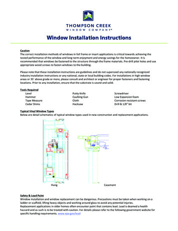
I;ire Fighting Sectional Commillee, CEO 22FOREWORDThis I ndian Standard was adopted by the Bureau of Indian Standards, after the draft finalized by the Fire FightingSectional Committee had been approved by the Civil Engineering Division Council.A sprinkler system consists of a water supply (or supplies) and one or more sprinkler installalions eachinstallation consists of a set of installation control valves and a pipe array fitted with sprinkler heads. Thesprinkler heads are fitted at specified locations at the roof or ceiling, and where necessary between racks, belowshelves, j'nside ovens or stoves or below obstructions. The main elements of a typical installation is shown inFig. 1.SPRINKLERHEADIN STAL L ATiONCONTROL VALVE SET(ALARM VALVE &MAIN 5 TOP VALVE)ARM PIPE(HORIZONTAL)FIG. 1 MAIN ELEMENTS OF A SPRINKLER INSTALLATIONA sprinkler has two functions to perform. It must first detect a fire, and must then provide an adequate distributionof water to control or extinguish it. Each function is performed separately and one is independent of the othercxcept insofar as early detection makes extinction easier because the fire has not grown large. The classic useor the sprinkler is in the hot gas layer which forms beneath the ceiling of an enclosure in which a fire isdeveloping.The sprinklers operate at pre-determined temperatures to discharge water over the affected part of the areabelow, the flow of water through the alarm valve initiating a fire alarm. The operating temperature is generallyselected to suil ambient temperature conditions. Only sprinklers in the vicinity of the fire, i.e., those whichbecome sufficiently healed, operate. It should not be assumed that the provision of sprinkler system entirelyobviates the need for other means of fighting fires and it is important to consider the fire precautions in thepremises as a whole.Structural fire resistance, escape routes, fire alarm systems, particular hazards needing other fire protectionmcthods, provision of hose reels and fire hydrants and portable fire extinguishers. etc, safe working and goodhandling methods, management supervision and good housekeeping all need consideration. It is essential thatsprinkler systems should be properly maintained to ensure opem ion when required. This routine is reliable to(Continued on third cover)
IS 15105 : 2002Indian StandardDESIGN AND INSTALLATION OF FIXEDAUTOMATIC SPRINKLER FIREEXTINGUISHING SYSTEMSCODE OF PRACTICE1 SCOPEThis standard lays down the requirements for thedesign and installation of fixed automatic sprinkler fireextinguishing system.2 REFERENCESThe Indian Standards listed in Annex A containprovisions which through reference in this text,constitute provisions of this standard. At the time ofpublication, the editions indicated were valid. Allstandards are subject to revision, and parties toagreements based on this standard are encouraged toinvestigate the possibility of applying the most recenteditions of the standards given in Annex A.3 DEFINITIONSFor the purpose of this code, the following definitionsshall apply.3.1 Alarm Test Valve -A valve through whichwater may be drawn to test the operation of the watermotor firm alarm and/or of any associated electric firealarm.3.2 Alarm Valve -A check valve, of the wet, dryor composite type, that also initiates the water motorfire alarm when the sprinkler installation operates.3.3 Alarm Valve, Pre-action - An alarm valvesuitable for a pre-action installation.3.4 Alarm Valve, Recycling -An alarm valvesuitable for a recycling installation.3.5 Alarm Valve, Wet- An alarm valve suitable fora wet installation.3.6 Arm Pipe -A pipe, other than the last sectionof a range pipe, feeding a single sprinkler.3.7 Assumed Maximum Area of Operation,Hydraulically Most Favourable Location - Thelocation in a sprinkler array of an AMAO of specifiedshape at which the water flow is the maximum for aspecific pressure.3.8 Assumed Maximum Area of Operation,Hydraulically Most Unfavourable Location - Thelocation in a sprinkler array of an AMAO of specifiedshape at which the water supply pressure is themaximum needed to give the specified design density.3.9 Cut-Off Sprinkler - A sprinkler protecting adoor or window between two areas only one of whichis protected by the sprinkler.3.10 Design Density - The minimum density ofdischarge, in mm/min of water, for which a sprinklerinstallation is designed, determined from the dischargeof a specified group of sprinklers, in }/min, divided by· m 2.the area covere d ,InA point on a distribution pipeof a pre-calculated installation, downstream of whichpipework is sized from tables and upstream of whichpipework is sized by hydraulic calculation.3.11 Design Point -3.12 Distribution Pipe -A pipe feeding either arange pipe directly or a single sprinkler on anon-terminal range pipe more than 300 mm long.3.13 Distribution Pipe Spur -A distribution pipefrom a main distribution pipe, to a terminal branchedpipe array.3.14 Drencher - A sprayer used to distribute waterover a surface to provide protection against fireexposure.3.15 Drop range pipe.A vertical pipe feeding a distribution or3.16 End-Side Array -A pipe anay with rangepipes on one side only of a distribution pipe (seeFig. 2 and 3).3.17 End"Centre Array - A pipe with range pipeson both sides of a distribution pipe (see Fig. 4 and 5).3.18 Fastener - A device for attaching pipe hangercomponents to a building structure or racking.3.19 Fire Door -A door and frame of specifiedfire resistance conforming to IS 3614 (Part 1) andIS 3614 (Part 2).3.20 Fire Resistance - The ability of a componentor the construction of a building to satisfy for a staled
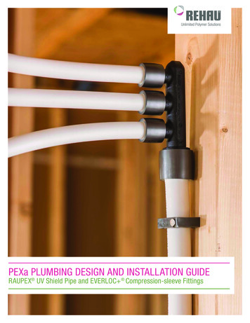
IS 15105 : 20020----0--]0- - - -0- -0----0--C - - - --1- --0- - - --1---0J-Q- --Q- - ---010- - - - - 0- ---10- - - - - 0- - -0- - - - - 0- - . - - - - - -I0- - - - -0- - -00-----0--0-.--- --0- - -FIG.4- -0- - - - -0 - --0-- . -0 - - - - -0Two END-CENTRE WITH END FEED3.21 Fire Shutter - A shutter and frame of specifiedfire resistance complying with IS 3614 with respect tostability and integrity.3.22 Fully Hydraulically Calculated - A termappJied to pipework sized as specified in 4.5.2 or aninstallation in which all the pipework downstream ofthe main installation control valve set is sized.0- - - - 0- - - - -0Ir--0- - - -- 0- - - --03.23 Hanger ---0-----0An assembly for suspendingpipework from the elements of building structure. - - 0 - - - - -0- - - --03.24 High-Rise System - A sprinkler system inwhich the highest sprinkler is more than 45 m abovethe lowest sprinkler or the sprinkler pumps whicheveris the lower.3.25 Hydraulic Alarm, Intermittent - Soundingof a hydraulic water motor alarm gong for intervalstotalling less than the alarm period.3 THREE END-SIDE WITH END FEED0- - - - - 0- - - - -0- - -r--0- -- - -0- - - - .00- - - - -0-- - -0-- - 1- - -0- - - - -0 - - - --00-- - - -0-- - - - -0---0----- ---------JI--0- - - --0- --- ----J,0---- -0- - - - -0--- - -0- ----0- ---'0 FIG.5---.{lperiod of time the appropriate criteria specified inIS 3809.l -FIG.--0- --- - - ()!'- -- -0- - - - 0- - - --01--- -----0-----0II1- . . -0 - --0- - - --0-j- -0-- ----0- --2 Two END-SIDE WITH CENTRAL FEED1- --0- - -t--1 --- o -JFIG.L-I - - - - 0- -- -i0-- - - - -0--0- - - - .()-4 - -0- - - - --0- - - - -0 - --1- -- r- - - -0- - - . -.()- - - - - 0- -J- - -0- -I0- - - . - 0- -0- - - -0THREE END-CENTRE WITH CENTRE FEED END FEED2
IS 15105 : 20023.26 Installation Sprinkler Installation - Part of asprinkler system comprising a set of installation maincontrol valves, the associated downstream pipes andsprinklers.3.27 Installation, Pre-action - A dry installation inwh ich the alarm val ve can be opened by anindependent fire detection system in the protectedarea.3.28 Instal1ation, Recycling -A pre-actioninstallation in which the alarm valve can be openedand closed repeatedly by a heat detection system.3.29 Installation, Wet Pipe An installation inwhich the pipework is always charged with water.3.30 Jockey Pump - A small pump used toreplenish minor water loss to avoid starting anautomatic suction or booster pump unnecessarily.3.31 Low-Rise System - A sprinkler system inwhich the highest sprinkler is not more than 45 mabove ground level or the sprinkler pumps.3.32 Main Distribution Pipe distribution pipe.A pipe feeding a3.33 Node - A point in pipework at which pressureand flow(s) are calculated; each node is a datum pointfor the purpose of hydraulic calculations in theinstallation.3.34 Precalculated - A term applied to pipeworksized as specified in 4.5.1 or an installation in whichpipe downstream of the design point is sized.3.35 Range Pipe A pipe feeding sprinkler directlyor via arm pipes of restricted length.3.36 Riser - A veltical pipe feeding a distributionor range pipe.3.37 Rosette Sprinkler Rosette - A plate coveringthe gap between shank or the body of a sprinklerprojecting through a suspended ceiling, and theceiling.3.38 Section - The part (which may be one or morezones) of an installation on a particular noor fed by aparticular riser.3.42 Sprinkler Conventional Pattern -Asprinkler that gives a spherical pattern of waterdischarge.3.43 Sprinkler Glass Bulb -A sprinkler whichopens when a liquid filled glass bulb bursts.3.44 Sprinkler Horizontal - A sprinkler in whichthe nozzle directs the water horizontally.A sprinkler3.45 Sprinkler Intermediate installed below, and additional to the roof or ceilingsprinklers.3.46 Sprinkler Pendent -A sprinkler in which thenozzle directs water downwards.3.47 Sprinkler, Roof or Ceiling protecting the roof or ceiling.A sprinkler3.48 Sprinkler Side-Wall Pattern - A sprinklerthat gives a downward paraboloid pattern discharge.3.49 Sprinkler Systelu - The entire means ofproviding sprinkler protection in the premisescomprising one or more sprinkler installation, the pipework to the installations and the water supply/suppliesexcept town mains and bodies of water such as lakesor canals.3.50 Sprinkler Upright - A sprinkler in which thenozzle directs the water upwards.3.51 Sprinkler Yoke Arms -The part of thesprinkler that retains the heat sensitive elements inload bearing contact with the sprinkler head valve.3.52 Staggered Sprinkler Layout -An off-set lay-out with the sprinklers displaced one half pitch alongthe range pipe relative to the next range or ranges.3.53 Standard Sprinkler Layout - A rectilinearlayout with the sprinkler aligned perpendicular to therun of the ranges.3.54 Suction Pump - An automatic pumpsupplying water to a sprinkler system from a suctiontank.3.55 Suitable for Sprinkler Use -3.39 Sling Rod - A rod with a sling eye or screwedends for supporting pipe clips, rings, band hangers, etc.A term appliedtoequipmentorcomponent accepted by the authoritiesas far a particular application in a sprinkler systemeither by a particular system or by compliance withspecified general criteria.3.40 Sprinkler, Ceiling or Flush Pattern - Apendent sprinkler for fitting partly above but with thetemperature sensitive element below, the lower planeof the ceiling.3.56 Supply Pipe - A pipe connecting a watersupply to a trunk main or the installation main controlvalve set(s); or a pipe supplying water to a privatereservoir, suction tank or gravity tank.3.41 Sprinkler Concealed - A recessed sprinklerwith a cover plate that disengages when the heat isapplied.3.57 Suspended Open Cell Ceiling - A ceiling ofregular open cell construction through which waterfrom sprinkler can be discharged freely.
IS 15105 : 20023.58 Terminal Main Configuration - A pipearray with only one water supply route to each rangepipe.FIG. 6 WINDOW/DoOR (PUCCA WALL)3.59 Terminal Range Configuration - A pipearray with only one water supply route from adistribution pipe.4.2.2 Iron or other non-masonry walls to be shown bya thin line and nature of construction indicated (seeFig. 7).3.60 Toggle Support- A swivel device for securinghangers to hollow sections ceiling or roofs.3.61 Trunk Mains -A pipe connection to two ormore water supply pipes to the installation maincontrol valve set(s).FIG. 7 GJ. WALLS (NON-MASONRY WALLS)3.62 User - The person responsible for or havingeffective control over the fire safety provision adoptedin or appropriate to the premises or the building.4.2.3 Fire walls, i.e., perfect party walls to be indicatedby the sign "T" at each end of the wall, or have theletters "P.P.W." alongside or across them at regularintervals and marked in distinctive colour (see Fig. 8).4 REQUIREMENTS REGARDING LAYOUTPLANSP.P.W.4.1 Layout plans should be drawn up in accordancewith the following requirements.P.P.W.·C" ,'.,';.-'!. ".:. :. . ' '. : . ' . ' f:. : .",.,, :.:.:.\1. ."''':, .!a,;.;;.-.,;;.;.;;;.;.a.;, -------4.1.1 Plans should be clear, contain all requireddetails including scale and point of compass andshould be dated.D.F. P. D.4.1.2 Plans of new installation shall show the entirecompound; all buildings therein, with their door andwindow openings, and the boundary walls. Buildingsunder construction and future extension envisaged,shall be indicated by the dotted lines. Plans ofextensions to approved existing installations need notshow the rest of the compound but sufficient detailsshall be given of the existing installations incorrelation to the extension, to enable the Authority'sInspection staff to check the plans and offercomments. In case of storeyed buildings, drawingssubmitted shall include plans of each storey togetherwith sectional elevations.i',. .-,- .1.- . FIG. 8 FIRE WALLS4.2.4 Fireproof doors and/or shutters to be marked asfollows:Single Fireproof Door and/or ShutterDouble Fireproof Door andlor ShutterS.F.D.D.F.D.4.2.5 Sky lights to be marked "Sky Lights" or "S.L.",4.2.6 Boiler to be shown by a rectangular figuremarked "Boiler".'BOILER'4.2.7 Sprinkler mains to be shown by a blue line; thediameter, length and number of pipes being markedalongside and specials and reducers to be clearlyindicated as below:- mm dia, lengths of -metre each (see Fig. 9)4.1.3 MaterialPlans should be on white paper or ammonia paper orFerro Prussiate paper.4.1.4 Plans should generally be prepared inaccordance with IS 962, shall not exceed 850 x 1 200mm in size and should be drawn to a scale of1:500 or 1: 1 000. In the case of very large compoundswith more than one risk, it is advisable to submitseparate plans for each risk with a key plan showingthe relative situation of the various risks, etc, in thecompound.lBLUE LINEFIG.9 SPRINKLER MAINS4.2.8 Sprinkler pumps to be clearly marked and thecapacity and head to be indicated in each case.4.2 Signs4.2.9 Pump(s) suction piping to be shown dotted anddiameter to be indicated (see Fig. 10).4.2.1 Pucca walls to be shown by double lines, doorsand windows being clearly marked (see Fig. 6).4
IS 15105 : 2002h)PUMPROOMj)mm k)FIG.10 PUMP SUCTION PIPEm)n)4.2.10 Fire service water tanks and reservoirs to beshown to scale (see Fig. 11). --p) -------------- - - - -------------uq)The location and type of main control valvesand location of alarm motors and gongs:The locationand details of any water flow andair or water pressure, alarm switches;The location and size of any tail-end air valves,subsidiary stop valves and drain valves:The drainage slope of the pipework;The location and specification of any orificeplate;A schedule listing the numbers of sprinklers,medium and high-velocity sprayers, etc, andthe area of protection; andA key to the symbols used.DEPTH4.3.2 Precalculated PipeworkCAPACITY-For precalculated pipework the following details shallbe given on, or with, the drawings:FIG. 11 FIRE SERVICE WATER TANK (RESERVOIR)a)4.2.11 Sprinkler trunk mains to be shown by a blueline, the sizes being marked alongside:b)mm DIA. spk. Main4.2.12 Fire alarm bells to be shown by a blue line, thesizes being marked "F.A.B.".4.2.13 Splinklered blocks to be marked "S",4.2.14 Electric cable(s) for the fire pump(s) to beshown in green line(s).Identification ofthe design points of each arrayon the layout drawing A summary of the pressure losses betweenthe control valve and the design points at thefollowing design rates or flow :1) In a light-hazard installation: 225 l/min,2) In a moderate-hazard installation: 1 0001Imin, and3) In a high hazard installation the flowcorresponding to the appropriate designdensity.NOTE - For light and moderate·hazard installations withprecalculated pipework the pressure needed at the design poinlis not stated. Instead the friction loss in the pipework betweenthe control valve and the design points is limited to apredetermined quantity, incorporated in the value specified forpressure at the control valves. Static head is added to thispressure to give the value defining the minimum actual watersupply running pressure. A typical summary of pressure lossesis shown in Table t.4.3 Installation Layout Drawings4.3.1 GeneralThe scale shall be not less than 1: 100. Layout drawi ngshall include the following information:4.3.3 Hydraulically Calculated PipeworkNorth point indication;b) The class or classes of installation accordingto hazard class including stock category anddesign storage height;c) Constructional details of floors, ceiling,roofs and exterior walls and walls separatingsprinklered and non-sprinklered areas;0) Sectional elevations of each floor of eachbuilding showing the distance of sprinkleredfrom ceiling, structural features, etc, whichaffect the sprinkler layout or the waterdistribution from the sprinklers e) The location and size of concealed roof orceiling voids, offices and other enclosuressealed at a level lower than the roof ofceiling proper f) Indication of trunking, staging, platforms,machinery, fluorescent light fittings, heaters,suspended open cell ceilings, etc, which mayadversely affect the sprinkler distribution;g) The sprinkler types(S) and temperatureratings(s);a)For hydraulically calculated pipework, the followingshall be given, with detailed calculations, either onpurpose designed work sheets or as a computerprint-out:a)For each design area of operation:1) the area identification;2) the hazard class;3) the specified density of discharge Onmm/min);4) the assumed area of maximum operation(AMAO) (in m2);5) the number of sprinklers in the AMAO;6) the sprinkler nominal orifice size (inmm);7) the maximum area covered per sprinkler8)5(in m2);detailed and dimensioned worki ngdrawings showing the following:i) the node or pipe reference schemeused to identify pipes, junctions.
IS 15105 : 2002ii)iii)iv)v)h)c)sprinkler heads and fittings whichneed hydraulic consideration;the position of the hydraulicallymost favourable AMAO;the position of the hydraulicallymost unfavourable AMAO;the four sprinklers upon which thedesign density is based; andthe height above datum of eachpoint of identified pressure value.main, from each water supply· to a main installatloncontrol valve set water supply test and drain valve andcontrol valve 'C' gauge (i.e., including the installationcontrol valves) is capable of providing the requiredpressure and flow at the installation control valve testand drain valve.4.5.2 Fully Hydraulically Calculated InstallationsWhere the pipework is fully hydraulically calculatedthe following additional details shall be given:For each operating sprinkler:1) the sprinkler node or reference number;2) the sprinkler nominal K factor;3) the flow through the sprinkler (in l/min);and4) the inlet pressure to the sprinkler orsprinkler assembly (in bar).a)b)For each hydraulically significant pipe:1) the pipe node or other reference;2) the pipe nominal bore (in mm);3) the hazen-williams constant (c or K factor) for the pipe;4) the flow through pipe (in l!min);5) the nominal fluid velocity (in m!sec);6) the length of pipe (in m);7) the numbers, types and equivalentlengths of fittings;8) the static head change in pipe (in m);9) the pressures at inlet and outlet of pipein bar;10) the friction loss in pipe (in bar); and11) the indication of flow direction.a modified pressure-flow characteristic graphindicating the usable pressure at any flow upto the maximum installation demand, andthe demand pressure-flow characteristic graphfor each installation for the hydraulically mostunfavourable (and if required the mostfavourable) AMAO with pressure taken as atthe control valve 'C' pressure gauge.5 CLASSIFICATION OF OCCUPANCIES5.1 As the water supply, pumping capacity and otherfeatures of the sprinkler installations depends not onlyon the size of the risk, but also on its fire growth andspread potentialities, the risks are to be categorizedunder the following classes for the purpose of designof the installation :a) Light hazard class,b) Moderate hazard class,c) High hazard class, andd) Storage hazards.NOTE - A broad classification of various occupancies is givenin National Building Code (Part IV) Fire Protection.A line diagram of the pipe layout shall be preparedshowing (he following:NOTE -5.1.1 Light Hazard ClassI) the node or pipe reference numbers;2) the distribution pipes;3) the range pipes;Non-industrial occupancies where the areas of rooms,2corridors, halls, etc, are not more than 125 m andabove are bounded by masonry! or R.C.C. walls raisedup to the roof and door openings therein protected bydoors.4) I he sprinkler heads under consideration;5) the four hydraulically most unfavourably placed heads; and6) the flow through. and pressure at the end of eachhydraulically significant pipe.4.4 Water Supply DrawingsTypical occupancies are as follows:The drawings shall show water supplies and pipeworktherefrom ul? to the installation control valves. Thedrawings shall be on an indicated scale of not less thanI: 100. A key to the symbols shall be induded. Theposition and type of stop and check valves and anypressure reducing valve, water meter, water lock,orifice plate and any connection supplying water forother services should be driesMuseumsNursing homesOffice buildingsPrisonsSchools, Colleges, etc.4.5 Hydraulic Calculation4.5.1 Pre-calculated InstallationsNOTE - if any occupancy or block within the light hazardrisk is larger than 125 m2 in area or having an area less than125 m2 in area but not bound on all sides as stipulated above. therisk should be classified as 'moderate' hazard.A hydraulic calculation (with relevant flow tests) sha]]show that each trunk main together with any branch6
IS 15105 : 2002Table 1 Statement of Distribution Pipe Losses Between the VariousDesign Points and the Installation Values(Clause 4.3.2)Run ofDistributionPipe fromValues toPipe Size(1)No. ofEquivalent PipeTotalTurns Length of Turns EquivalentPressure Loss at Design Flow RateArPipe LengthPipe(m)(mBars)Losses(mm)A-floor 3Pipe III240473755TotalStaticDifferenceHead Gain (ph)(mBars)(mBars)(8)""(9)0 473B-tloor 3658010071.9203724.31.923Total101374300 5268150783380 403D-floor265801008.88.8316.319.5Total306084390380 10E-tloor 60 328F-floor 165801008.99.92.538.912.92.5Total30920511525760- 235NOTE - The pressure drop caused by any orifice plate in the distribution pipework should be taken into account by a correspondingreduction in the static head gain.5.1.2 Moderate Hazard (Manufacturing Occupancies)Car parking areas within building or basementCementCeramicsChemicalsCinematographic and T.V. productionfbroadcastingstudiosCloth processorsCon fectioneriesDairiesDehydrated vegetable factoriesDepartmental stores/Retail shopsElectronic equipment and assemblyEngineering workshopsFibreboard factoriesFlax, jute and hemp millsFlour millsFood and beveragesAbattoirsAbrasive wheel and powderAircraft factories (exc1uding hangers)Airport terminal buildingsBakeriesBiscuit factoriesBookbinders. publishe sBreweriesBoot and shoe unitsCablesCandleCardboard factoriesCarpentry and furniture [not involving foam/foamplastics]Carpets7
IS 15105 : 2002CATEGORY-IIGlass factoriesHosiery and garmentJewelleryLaboratoriesMotor garagesPaint shopsPaper millsPhotographic film factoriesPlywood factoriesPrinting pressesRestaurants and cafesRope factoriesRubber and plastics (other than foam plastics)Soap factoriesSugar millsSynthetic fibres/yam factoriesTanneriesTextile miJIsTimber and wood-working (except saw mills)TheatresTobacco factoriesWoodwoolWoollen millsVermicel1iWax factoriesBatteries, Baled cotton/synthetic fibres, Books, Baledcork, Baled wa'ste paper, Cartons containing alcohols( in canslbottles), Cartons of canned lacquers whichdry by solvent evaporation, Chipboard, Cardboardrolls (horizontally stored), Cereals/GrainslFoodstufflFlour/Sugar in sacks, Cellulose/Cellulose pulp,Electrical goods other than those stated in Category-:.I,Flammable liquids in non-combustible containers,Leather goods, Palletised liquor stocks, Plastics(non-foamed, other than cellulose nitrate), Rolled pulpand paper and asphaJted paper (Horizontal storage),Veneer sheets, Wooden patterns, Metal/woodenfurnitures with plastic seats, etc.CATEGORY ·IIIBitumenIWax coated paper, Candles, Carbon black,Card board rolls (vertically stored), Charcoal, Coal,cellulose nitrate, Foamed plastic and foam rubberproducts, Flammable liquids in combustiblecontainers, Linoleum products, Matches, Plasticsother than those stated in Category-II, Rol1ed pulp andpaper and asphalted paper (vertical storage), Rubbergoods including tyres and tubes, Sawn timber,Ventilated wood stacks, Waxed and asphalt coatedpapers and containers in cartons, Woodwool, woodenpallets and flats (idle), All materials having wrappingsor pre-formed containers of foamed plastics, etc.5.1.3 High Hazard (Manufacturing Occupancies)Aircraft hangersBitumen and wax coated paperCelluloid goodsCellulose nitrateCigarette filterDi sti IleriesDuplicating/stencil paper explosivesFire worksFloor cloth and Ii noleumFoam plastics and foam rubberHessian c10thffar felt match factoriesOil millsPaint, colour and varnish factoriesResin, rosine, turpentine and lamp blackRubber substitutes making unitsSaw millsSurgical cotton, mattress and pillow makersTar distillation unitsWoodwool manufacturersCATEGORY-IVOffcuts and random pieces of foamed plastic orfOi.HrlCd rubber rolls of sheets of foamed plastic orfoamed rubber, Foam mattress, Expanded polystyrenepackaging, Foam upholstery, etc.6 PLANNING6.1 Initial Considerations6.1.1 Outline DesignConsideration should be given to any benefits thatmight be gained by changes in building design, workprocedures, etc, when preparing the outline design. Inplanning site layout and building design, particularconsideration should be given to the following:a)5.1.4 Storage Occupanciesb)Storage risks (stacked or high-piled) are categorisedunder four classes as per classifications below:c)CATEGORY-]Carpets, Non-synthetic/synthetic yarn and fabrics,Mechanical and electrical goods (dominantly metalparts) and hardware items, Glassware and crockery,fibreboards, groceries, metal goods, Papers other thanthose listed under categories 2 and 3 below, Powderedand canned foods, Plastic/glass bottles containingnon-flammable liquids, etc.d)e)the occupancy hazard class and goods categorywhich determine the water discharge densityand water supply pressure and now the siting of any main water supply connection(s);the siting of any water supply tank(s) or reservoir;the siting of any pump house;the maximum quantity of water available fromthe supply source compared with the systemrequirements t)8the location of sprinkler installation controlvalves, together with the access thereto,
IS 15105 : 2002g)h)indication of their position, and the disposal ofdrainage and water mpply test water;the source and means of supply of electricpower, etc; andthe protection of valve sets, pipework andsprinklers against accidental damage.6.2.2 Exceptions (Buildings and Parts of BuildingsNot Sprinkler-Protected)Obligatory exceptions, sprinkler protection shall notbe provided in the following parts of a building orplant:a)6.1.2 It is important to consider building design in thecontext of fire protection, e.g., choice of materials,support of sprinkler pipework having regard to theload imposed on structure by the weight of sprinklerpipework and the contained water, need for inbuiltdrainage (which is strongly advised for computerareas) or raising of base of stacked goo
3.31 Low-Rise System - A sprinkler system in which the highest sprinkler is not more than 45 m above ground level or the sprinkler pumps. 3.32 Main Distribution Pipe - A pipe feeding a distribution pipe. 3.33 Node - A point in pipework at which pressure and flow(s) are calculated; each node is a datum point