Transcription
CaliforniaDesign and Installation Manualfor Advanced Enviro-Septic (AES)Wastewater SystemsTable of ContentsFor more detailed design and installation information on AES, please contact InfiltratorWater Technologies at (800) 221-4436 or Presby Environmental, Inc. at (800) 473-5298.www.infiltratorwater.com www.presbyeco.com1.0 INTRODUCTION1.1 Background1.2 System Components2.0 SYSTEM DESIGN2.1 Sizing2.2 Design Procedure2.3 Design Examples2.4 Design Specifications2.5 SystemConfigurations2.6 Pump Systems2.7 Venting2.8 Site Selection3.0 INSTALLATION4.0 REJUVENATION ANDEXPANSION5.0 OPERATION ANDMAINTENANCE6.0 WARRANTY334557791215161920232425JANUARY 2020
The information in this Manual is subject to change without notice. We recommend that you check your state’spage on our website on a regular basis for updated information. Your suggestions and comments are welcome.Please contact us at:Infiltrator Water Technologies4 Business Park Road, Old Saybrook, CT 06475(800) 473-5298 resby Environmental, Inc.143 Airport RoadWhitefield, NH 03598Phone: 1-800-473-5298 Fax: (603) 837-9864Website: www.presbyenvironmental.comThe products and methods depicted in this Manual are protected by one or more patents.Advanced Enviro-Septic is a registered trademark of Presby Environmental Inc.IMPORTANT NOTICE: This Manual is intended ONLY for use in designing and installing Presby Environmental’sAdvanced Enviro-Septic Wastewater Treatment Systems. The processes and design criteria contained herein arebased solely on our experience with and testing of Advanced Enviro-Septic . Substitution of any other product isprohibited. Presby Environmental, Inc. January 2020All Rights ReservedInfiltrator Water Technologies California Design & Installation Specifications, January 2020 Edition
1.0 INTRODUCTION1.1 BackgroundThe Advanced Enviro-Septic (AES) WastewaterTreatment System utilizes a unique combination ofcomponents that work together to treat effluent andprevent suspended solids from sealing the underlyingsoil. Comprised of a patented corrugated, perforatedplastic pipe with interior skimmer tabs and coolingridges, the large-diameter pipe retains solids while theBio-Accelerator fabric, coarse fibers, and geo-textilefabric provide multiple bacterial surfaces to treateffluent prior to its contact with the receiving soils.The continual cycling of effluent (the rising and fallingof liquid inside the pipe) enhances bacterial growth.The AES system is completely passive, and yet providesincreased aeration and a greater bacterial treatmentarea than traditional systems. The result is a systemthat is more efficient, lasts longer, and has a virtuallyno negative environmental impact.The AES system has been successfully tested andcertified to NSF/ANSI 40, Class I (a certificationtypically given to mechanical aeration devices) andBNQ Class I, II, III standards.Additional system benefits include: requires a smaller area installs easily and quickly eliminates the need for environmentallyimpactful washed stone adapts easily to residential, commercial and difficult sites prevents formation of organic material at the receiving soil interface blends “septic mounds” into sloping terrain safely recharges groundwaterEnvironmental Standards and Technical SupportAll AES systems shall be designed and installed in compliance with the procedures and specifications detailed inthis Manual and in the product’s county approval. This Manual is to be used in conjunction with the CaliforniaState Onsite Wastewater Treatment System Policy (OWTS Policy), individual Local Agency Management Programs(LAMPs), and county regulations. In the event of contradictions between this Manual and these policies orregulations, PEI should be contacted for technical assistance at (800) 473-5298.Certification RequirementsDesigners and installers who have not previously attended a PEI certification course are required to obtaincertification. Certification is obtained by attending a certification course presented by PEI or its sanctionedrepresentative or by viewing tutorial videos on our website and then successfully passing a short assessment test.PEI recommends professionals involved in the inspection or review of AES systems also become PEI certified.Infiltrator Water Technologies California Design & Installation Manual, January 2020 Edition3
1.0 INTRODUCTION1.2 System ComponentsAES Pipe nominal exterior diameter of 12 inholding capacity of 5.8 gallons perfoot10 ft length of AES pipe is flexibleenough to bend up to 90 and canbe cut to any lengthmade with a significant amountrecycled materialOffset Adapter - A 12 in plastic fitting witha single inlet hole oriented in the 12 o’clockposition and designed to accept a 4 insewer line, raised connection or vent pipe.Double Offset Adapter - A 12 in plastic fitting with two 4 in holes designed to accept a 4 in inlet pipe, raisedconnection, vent or vent manifold, and/or bottom drain, depending upon the requirements of the designconfiguration.Coupling - A plastic fitting used to create a connection between two pieces of AES pipe.System Sand - The system sand that surrounds the AES pipes is an essential component of the system. It is criticalthat the correct type and amount of system sand is used during construction. System sand shall be coarse to verycoarse, clean, granular sand, free of organic matter. System sand is placed a minimum of 3 in above and 6 inbelow, between, and around the outer perimeter of the AES pipes. It shall adhere to all of the followingpercentage and quality restrictions:Sieve Size3/4 in (19 mm)System Sand SpecificationPercent Retained on Sieve (by weight)0#10 (2 mm)0 - 35#35 (0.50 mm)40 - 90Note: not more than 3% allowed to pass the #200 sieve (verified by washingsample per requirements of ASTM C-117)System Sand Bed Height DimensionThe height of an AES sand bed measures 21 in minimum (not including cover material): minimum of 6 in of system sand below the AES pipe; 12 in diameter of the pipe; and minimum of 3 in of system sand above the AES pipe.System Sand Acceptable Alternative - ASTM C-33 (concrete sand), natural or manufactured sand, with notmore than 3% passing the #200 sieve (verified by washing the sample per the requirements of ASTM C-117 asnoted in the ASTM C-33 specification) may be used as an acceptable alternate material for use as system sand.Sand Fill - Sand fill may be used to raise the elevation of the system in order to meet the required separationdistance from the SHWT or restrictive feature or in side-slope tapers. No organic material or stones larger than 6 inare allowed in the sand fill. System sand may be used in place of sand fill.Infiltrator Water Technologies California Design & Installation Manual, January 2020 Edition4
2.0 SYSTEM DESIGN2.1 SizingNew System Design RequirementsAES systems for new construction are designed in a bed configuration with a 30% reduction of the system sandbed area as allowed in the OWTS Policy. Allowance of the 30% reduction factor, in all or part, is at the discretion ofeach Local Agency and their local requirements. Please consult with the Local Agency prior to submitting designplans and the permit application. The minimum system sand bed area (SSBA) for the AES is calculated by dividingthe design flow by the conventional application rate in Tables A and B and multiplying by 0.7 (30% reduction):(Design Flow Application Rate) x 0.7 Minimum System Sand Bed Area (SSBA)For example, a design flow of 500 gpd, a percolation rate of 33 minutes / inch (mpi) and application rate of0.5 gpd/ ft2 is calculated as 500 gpd 0.5 gpd/ ft2 x 0.7 700 ft2 minimum SSBA.Other critical specifications include:a) Maximum site and system slope are determined by Table D (See p.11 for details.) based upon thepercolation rate.b) Minimum AES pipe amount per Table C.c) Minimum AES pipe spacing is 1.5 ft center-to-center.Table A: Application Rates as Determined from Stabilized Percolation Rate Percolation RatePercolationRate(mpi) 1Application pd/ft2)PercolationRate(mpi)ApplicationRate (gpd/ft2)Requires Local360.467640.187Management .197890.103340.489620.194900.1350.478630.19 91-1200.1Note: Values extracted from the OWTS Policy, Table 3 (p.24). Contact PEI for sites with percolation rates over 120 or forguidance on designing replacement systems.Infiltrator Water Technologies California Design & Installation Manual, January 2020 Edition5
2.0 SYSTEM DESIGNTable B: Application Rates as Determined from Soil CharacteristicsSoil TextureCoarse Sand, Sand, Loamy CoarseSand, Loamy SandFine Sand, Very Fine Sand, LoamyFine Sand, Loamy Very Fine SandCoarse Sandy Loam, Sandy LoamSoil Structure ShapeSingle grainStructurelessSingle , StrongWeakModerate, StrongStructurelessWeak, Moderate, StrongWeakModerate, StrongStructurelessWeak, Moderate, StrongWeakModerate, StrongStructurelessWeak, Moderate, StrongWeakModerate, StrongStructurelessWeak, Moderate, StrongWeakModerate, StrongStructurelessWeak, Moderate, StrongWeakModerate, StrongPlatyPrismatic, Blocky, GranularFine Sandy Loam, very fine SandyLoamMassivePlatyPrismatic, Blocky, GranularMassivePlatyLoamPrismatic, Blocky, GranularMassivePlatySilt LoamPrismatec, Blocky, GranularSandy Clay Loam, Clay Loam, SiltyClay LoamSandy Clay, Clay, or Silty ClayGradeMassivePlatyPrismatic, Blocky, GranularMassivePlatyPrismatic, Blocky, GranularMaximum SoilApplication dProhibited0.2Note: Soils listed as prohibited may be allowed under the authority of the Regional Water Board, or as allowed under anapproved Local Agency Management Program per Tier 2.Replacement System Design RequirementsAES systems for replacement systems are designed using a “best-fit” bed configuration, depending on siteconstraints. If site conditions allow, the minimum SSBA for replacement systems should be calculated using TablesA and B with the 30% reduction (as in new system designs) as detailed above. For replacement systems with siteconstraints that preclude use of the minimum SSBA for new systems, contact PEI Technical Advisors for designassistance. The SSBA should be sized according to the specifications in this Manual to the greatest extentpracticable. At their discretion, Local Agencies may allow decreased sizing requirements in order to accommodatethe existing size of the site or setback requirements. Please consult with the Local Agency as to what they willallow prior to submitting design plans and a permit application.Table C: AES Pipe RequirementsSystem TypeResidential SystemAES Pipe Loading Rate70 ft/brCommercial (Non-Residential) System*2.14 gpd/ft*Assumes residential strength effluent. Contact Presby Environmental for technicalassistance with high strength wastewater.Infiltrator Water Technologies California Design & Installation Manual, January 2020 Edition6
2.0 SYSTEM DESIGN2.2 Design ProcedureStep #1:Determine System Sand Bed Area Required (SSBA)For new and replacement systems, not more than a 30% reduction is allowed per the OWTS Policy. Useminimum system sand bed area (SSBA) equation (Design Flow Application Rate from Table A or B) x0.7. For replacement systems with site constraints size the SSBA to the greatest extent practicable,contact PEI Technical Advisors for design assistance.Step #2:Choose Allowable System SlopeFrom Table D: choose an allowable system slope and bed configuration using the soil’s percolation rate.Step #3:Calculate the Minimum Amount of AES Pipe NeededFrom Table C: Calculate the minimum amount of AES pipe needed: 70 ft/br for residential applicationsor 2.14 gpd/ft for commercial applications treating residential strength effluent. Contact TechnicalSupport for high strength wastewater.Step #4:Calculate the Number of Serial Sections NeededCalculate the minimum number of serial sections required (does not apply to parallel configurationdesigns): divide the design flow by 750 gpd (then round up to nearest whole number). For additionalinformation on serial distribution, see System Configurations, pg. 11.Step #5:Determine Row Length and Quantity NeededSelect a row length suitable for the site and calculate the number of rows (round up to whole number).The number of rows must be evenly divisible by the number of serial sections required (add rows asnecessary).Step #6:Determine Pipe Layout Width (PLW)Calculate the pipe layout width (PLW) as follows:PLW [(# of rows – 1) x spacing (1.5 minimum)] 1.Step #7:Determine Minimum System Sand Bed Width (SSBW)Calculate the minimum system sand bed width (SSBW) by dividing the system sand bed area (SSBA)from Step #2 by the selected row length from Step #5 1 ft (allows 6 in of sand beyond the end of therows).Step #8:Verify Final Bed Width Requirements:Verify the minimum SSBW from Step #7 will cover all the rows in the bed:a) Level beds and beds sloping less than 5%: If the minimum SSBW is less than the (PLW 1 ft), use(PLW 1 ft) as the new minimum SSBW.b) Beds sloping 5%: If the minimum SSBW is less than the (PLW 3.5 ft), use (PLW 3.5 ft) as thenew minimum SSBW. Adding 3.5 ft to the pipe layout width accounts for a 2.5 ft system sandextension on the down slope side of the field.Step #9:Calculate System Sand Extensions (SSEs):a) Level beds: SSEs are placed on each side of AES pipes [SSBW – (PLW 1)] 2. There will be noSSEs if the SSBW (PLW 1 ft).b) Sloping Beds: SSEs are placed entirely on the down slope side of the bed SSBW – (PLW 1) andmust be at least 2.5 ft (3 ft from the edge of the AES pipe) for beds sloping greater than 5%.2.3 Design ExamplesDesign Example #1 (new system, serial distribution configuration)Single family residence, 4 bedrooms (600 gpd), percolation rate of 25 mpi (sand), level site.Step #1:Soil’s conventional application rate from Table A or B 0.589 gpd/ft²; SSBA (600 gpd 0.589 gpd/ft²)x 0.7 (reduction factor) 714 ft² minimum.Infiltrator Water Technologies California Design & Installation Manual, January 2020 Edition7
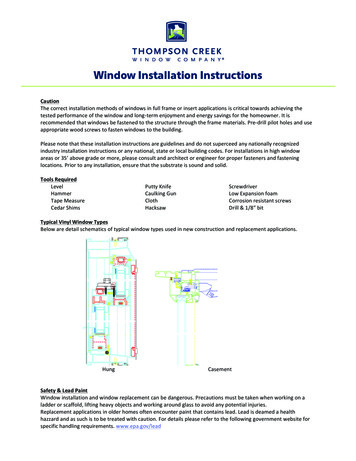
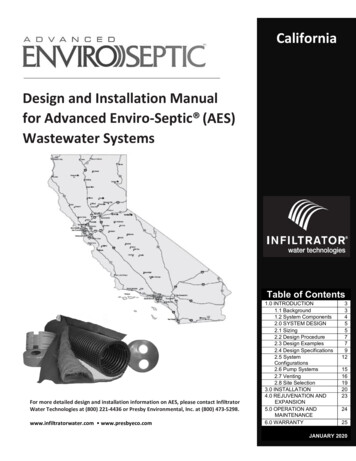
2.0 SYSTEM DESIGNStep #2:Step #3:Step #4:Step #5:Step #6:Step #7:Step #8:Step #9:Table D allows up to 25% system slope for 25 mpi, however this system will be level.AES pipe required using 70 ft/br from Table C 280 ft minimum (4 br X 70).Serial sections required 600 gpd 750 gpd/section 0.8 (round up to 1).Using a row length of 70 ft requires four rows (280 ft 70 ft 4).PLW [(4– 1) x 1.5] 1 5.5 ft when using four 70 ft long rows spaced at 1.5 ft center-to-center.Minimum SSBW 714 ft² (70 ft 1 ft) 10.06 ft, round up to 10.5 ft for ease of construction.a) 10.5 ft SSBW is more than 6.5 ft (5.5 ft PLW 1 ft); use 10.5 ft as the minimum SSBW.b) Not required.a) SSE [10.5 ft – (5.5 ft 1 ft)] 2 2.0 ft on each side of level bed.b) Not required.Illustration of Example #1, Basic Serial Distribution:Design Example #2 (new system, parallel distribution configuration)Single family residence, 3 bedrooms (450 gpd), percolation rate of 10 mpi (sand), 11% sloping site.Step #1:Step #2:Step #3:Step #4:Step #5:Step #6:Step #7:Step #8:Step #9Soil’s conventional application rate from Table A or B 0.8 gpd/ft²; SSBA (450 gpd 0.8 gpd/ft²) x 0.7 393.75 ft² minimum (Round up to 394 ft2).Table D allows up to 25% system slope for 10 mpi and our system will only slope 11%.AES pipe required using 70 ft/br from Table C 210 ft minimum (3 br X 70).System designed using parallel distribution layout, this step is not needed proceed to Step #5.Using a row length of 70 ft requires three rows (210 ft 70 ft 3 rows).PLW [(3– 1) x 1.5] 1 ft 4 ft when using three 70 ft long rows spaced at 1.5 ft center-to-center.Minimum SSBW 394 ft² (70 ft 1 ft) 5.55 ft (round up to 5.75 ft).a) Bed is sloping, go to b).b) 5.75 is less than 7.5 ft (4 ft PLW 3.5 ft) use 7.5 ft as the new minimum SSBW.a) System is sloping go to b).b) 7.5 ft – (4 1). 2.5 ft (3 ft from edge of the AES pipe). The SSE will be placed on the downslope sideof the bed.Illustration of Example #2, Basic Serial Distribution:Infiltrator Water Technologies California Design & Installation Manual, January 2020 Edition8
2.0 SYSTEM DESIGN2.4 Design SpecificationsThe AES system shall be designed in accordance with this Manual and can be installed using either bed or trenchdesign utilizing any of the design configurations outlined in this Manual.Daily Design FlowResidential daily design flow for AES systems is calculated in accordance with county regulations. Systems servicingmore than two residences shall use the commercial specifications detailed in the sizing tables. The minimum dailydesign flow shall be one bedroom for any single-family residential system and 300 gpd for any commercial system.Septic TankThe AES system is designed to treat effluent that has received “primary treatment” in a standard septic tank.Septic tanks shall be sized in accordance with county regulations.Water Purification Systems Water purification systems and water softeners should not discharge into any AES system.If there is no alternative means of disposing of this backwash other than in the system, the system willneed to be “oversized.” Calculate the total amount of backwash in gpd, multiply by 2, and add thisamount to the daily design flow when determining the field and septic tank sizing.Water purification systems and water softeners require regular routine maintenance; consult and followthe manufacturer’s maintenance recommendations.Pressure DistributionThe use of pressure distribution lines in AES systems is prohibited. Pumps may be utilized when necessary only togain elevation and to feed a distribution box which then distributes effluent by gravity to the AES field. Siphondosing is permitted; adequate venting is required in a siphon-dosed system or pumped system, which may requirean additional high vent (referred to as “differential venting”).Effluent (Wastewater) StrengthThe AES pipe requirement for bed or trench systems is based on residential strength effluent, which has receivedprimary treatment in a septic tank. Designing a system that will treat higher strength wastes requires additionalAES pipe. In these situations, our Technical Advisors shall be consulted for recommendations at (800) 473-5298.Effluent Filters Effluent filters are not recommended for use with AES systems.If used, effluent filters shall be maintained on at least an annual basis. Follow manufacturer’s instructionsregarding required inspections, cleaning and maintenance of the effluent filter.If an effluent filter is required, a schematic for proper installation of the venting system with the use of aneffluent filter is provided on pg. 18 of this manual.Effluent filters must allow the free passage of air to ensure the proper functioning of the system.Charcoal filters in vent stacks (for odor control) are not recommended by PEI. They can block air flow andpotentially shorten system life.Flow Equalizers RequiredAll distribution boxes used to divide effluent flow require flow equalizers in their outlets. A flow equalizer is anadjustable plastic insert installed in the outlet holes of a distribution box to equalize effluent distribution to eachoutlet whenever flow is divided. Each bed or section of combination serial distributionis limited to a maximum of 15 gallons per minute (gpm), due to the flow constraints ofthe equalizers. Example: pumping to a combination system with 3 sections (using 3 Dbox outlets). The maximum delivery rate is (3 x 15) 45 gpm. Always provide a meansof velocity reduction when needed. All systems with combination serial distribution ormultiple bed distribution shall use flow equalizers in each distribution box outlet.Infiltrator Water Technologies California Design & Installation Manual, January 2020 Edition9
2.0 SYSTEM DESIGNTwo Inch RuleThe outlet of a septic tank or distribution box shall beset at least 2 in above the highest inlet of the AES row,with the connecting pipe slope not less than 1%(approximately 1/8 in per foot). Illustration of 2 in rule:Row Requirements All beds shall have at least 2 rows.Maximum row length for any system is 100 ft of pipe.o AES systems are recommended to be designed andinstalled as long and narrow as practical for the site.Recommended minimum row length is 30 ft of pipe.o A combination (or D-box) distribution system shallbe used if any row length is less than 30 ft.o A minimum of two D-box outlets must be used andthe field must be vented.Minimum center-to-center spacing is 1.5 ft for allsystems. Spacing may be increased at the discretion ofthe system designer or as needed to meet the requiredSSBA.Sewn seam must be oriented in the 12 o'clock position. This correctly orients the Bio-Accelerator fabric inthe 6 o'clock position.For level beds: the AES rows shall be centered in the middle of the system sand bed area and any systemsand extensions divided evenly on both sides.For sloping beds: the elevations for each AES row must be provided on the drawing. All rows shall begrouped 6 in from the up-slope edge of the system sand bed area (SSBA) with any system sand extensionsplaced entirely on the downslope side. Systems sloping greater than 5% require a 2.5 ft system sandextension on the downslope side of the bed (3 ft when measured from the pipe).Each row must be laid level to within /- ½ in (total of 1 in) of the specified elevation and preferablyshould be parallel to the contour of the site.It is most convenient if row lengths are designed in exact 10 ft increments to accommodate the length ofthe AES pipe as manufactured. However, AES pipe lengths can be cut to any length.System Sand ExtensionsSystem sand extensions are placed on the down slope side of sloping systems and equally divided on each side oflevel systems. The system sand extension is measured from the tall portion of the system sand bed. In systemssloping more than 5%, a 2.5 ft minimum system sand extension is required. The system sand extension area is aminimum of 6 in deep. For multiple slope beds, if any portion of the bed has a system slope greater than 5%, a 2.5ft minimum system sand extension is required. Illustration of bed with multiple slopes below.Separation Distances (Horizontal and Vertical)Horizontal separation distances are measured from the outermost edge of the system sand bed area. Verticalseparation distances are measured from the system sand/receiving soil interface.Sloping Sites and Sloping Mound Systems The percentage of slope in all system drawings refersto the slope of the system, not the existing terrain("site slope") and refers to the slope of the bed itself("system slope").The system slope and the site slope do not have tobe the same.Maximum site slope is 33% and maximum systemslope is 25%.Infiltrator Water Technologies California Design & Installation Manual, January 2020 Edition10
2.0 SYSTEM DESIGNTable D: Allowable SlopesSoil TextureSand, Loamy Sand, Sandy Loam, LoamSandy Clay Loam, Silty Loam, Silty ClayLoam, Clay LoamSandy Clay, Silty Clay, ClayPercolation RateMinutes per Inch(mpi)Up to 3031 - 4041 - 5051 - 6061 -120% SystemSlopeMaximum252015105% Site SlopeMaximum332520155Barrier Materials over System SandNo barrier materials (hay, straw, tarps, etc.) are to be placed between the system sand and cover material. Theonly exception is the placement of the specified fabric to achieve H-20 loading requirements.H-20 LoadingIf a system is to be installed below an area that will be subjected to vehicular traffic, it must be designed andconstructed as depicted in order to protect the system from compaction and/or damage. Note that a layer ofstabilization fabric is added between the 6 in system sand and the cover material. All H-20 systems require venting.VENTING REQ'D FORALL H-20 SYSTEMSPAVEMENT OR OTHERHARDSCAPEVENT MANIFOLD(IF REQ'D)EXTEND FABRIC 3' MIN BEYOND EDGEOF PIPE (ALL EDGES)BANK RUN GRAVEL(NO STONES OVER 2"Ø)12" MIN (BELOW PAVEMENT)FABRICBOTTOM DRAINSRECOMMENDED WHEN PRESBYPIPE ENDS ARE INACCESSIBLESYSTEM SAND 6" MIN ABOVE AND BELOW PRESBYPIPES. NO SAND VOIDS ALLOWED. WALK BETWEENROWS TO ENSURE SAND FILLS ALL VOIDS AROUNDPRESBY PIPES (REPEAT IF NECESSARY).6" SYSTEM SANDINSTALL STABILIZATION FABRIC ON TOP OF THE6" OF SYSTEM SAND OVER THE PRESBY PIPES.FABRIC TO HAVE A "GRAB TENSILE STRENGTHOF 315 LBS PER ASTM D 4632"PRESBY PIPE WITH DOUBLEOFFSET ADAPTERNOTE:THE ONLY SOIL COMPACTION THAT SHOULD TAKE PLACE IS AT THE POINT OF PREPARATION FOR PAVEMENT.Bottom DrainA bottom drain is a line connected to the hole in the 6 o’clock position of a double offset adapter at the end ofeach row which drains to a sump and is utilized to lower the water level in a saturated system or to facilitatesystem rejuvenation. There must be 18 in from the bottom of the sump to the bottom of the drain. The sumpshould be brought above the final grade and have a locking or mechanically fastened cover.Illustrations of a bottom drain:Infiltrator Water Technologies California Design & Installation Manual, January 2020 Edition11
2.0 SYSTEM DESIGN2.5 System ConfigurationsElevated Bed Systems (Mounds)Elevated beds are designed for sites with soil, depth to groundwater or restrictive feature constraints that do notallow for in-ground bed systems. An elevated bed system is a soil absorption field with any part of the systemabove original grade. Side-slope tapering is used to blend the raised portion of the system with the existing grade.Elevated bed systems require 6 in fill extensions on each side (measured from the pipe), after which side-slopetapering is to be a maximum of 3 horizontal feet for each 1 ft of vertical drop until it meets existing grade. Insystems sloping greater than 5%, there must be a minimum of 2.5 ft. of system sand extension (3 ft measured fromthe pipe) beyond the last down-slope row of pipe. There must be a minimum of 12 in of cover material over theends of all system sand extensions (if present).Illustration of an elevated level bed:Illustration of an elevated sloping bed:In-Ground Bed SystemsSystems are installed below existing grade for sites with no soil restrictive features to limit placement. In-groundsystems that slope over 5% require a 2.5 ft system sand extension on the downhill side of the field. In-ground onlevel site:Trench SystemsAES pipe may be installed in trench configurations on level or sloping terrain and may utilize serial, combination,butterfly, or parallel distribution. Trench systems incorporate one or more rows of AES pipe per trench. Aminimum of 3 in of system sand is required above and 6 in below, between, and around the perimeter of the AESpipe. Consult state/local rules for acceptable trench width and/or required trench separation.Basic Serial DistributionAES rows are connected in series at the ends with raised connections, using offset adapters. Used for single beds of 750 gpd or less and multiple beds where each bedreceives 750 gpd or less. Incorporates rows in serial distribution in a single bed. Rows shall meet requirements outlined in the design criteria above. Gravity fed basic serial systems may be fed directly from the septic tank. Bed may be constructed with unusual shapes to avoid site obstacles ormeet setback requirements.Infiltrator Water Technologies California Design & Installation Manual, January 2020 Edition12
2.0 SYSTEM DESIGNIllustration of basic serial systems bed designs:Butterfly Configuration A “butterfly configuration” is considered a single bed system with two or more sections extending inopposite directions from the D-box along the contour.Butterfly configurations are generally used to accommodate bed lengths longer than the maximum rowlength of 100 ft.Beds can contain any number of serial sections.Rows shall meet requirements outlined in the design criteria above.Illustration of a butterfly configuration bed design:Combination Serial DistributionCombination serial distribution within one bed, or multiple beds, is required for systems with daily design flowsgreater than 750 gpd. Effluent flow is divided evenly to each section using a distribution box with flow equalizers. Consists of two or more serial sections (with a maximumloading of 750 gpd/section) installed in a single bed, eachreceiving an equal amount of effluent from a D-box withflow equalizers.Each section consists of a series of AES rows connected atthe ends with raised connections, using offset adaptersand PVC sewer and drainpipe.There is no limit on the number of sections within a bed.Each section shall have at least the same minimum linear feet of pipe determined by dividing the totalminimum linear feet required in the system by the number of sections required.A section may exceed the minimum linear feet required.When the vent manifold is on the same side as the serial section inlets, the manifold runs over the top ofthese inlets.Rows must meet requirements outlined in the design criteria above except rows within a section may vary inlength to accommodate site constraints as shown below.Infiltrator Water Technologies California Design & Installation Manual, January 2020 Edition13
2.0 SYSTEM DESIGNIllustrations of combination serial systems:D-box (Parallel) Distribution All rows in this configuration must be t
1.2 System Components. 2.3 Design Examples . Design and Installation Manual for Advanced Enviro-Septic (AES) Wastewater Systems. California . Table of Contents 1.0 INTRODUCTION 3 1.1 Background 3 4 2.0 SYSTEM DESIGN 5 2.1 Sizing 5 2.2 Design Procedure 7 7 2.4 Design Specifications 9 2.5 System Configurations 12 2.6 Pump Systems 15 2.7 Venting 16