Transcription
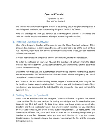
Quartus II A ModelSim G³ j ( )1. If Quartus II 13.1.0.162 was not installed in your PC, download from CIS StorageServer and install it (ModelSim will be installed together automatically)2. Before running Quartus II 13.1, create a working directory ( Â ),Documents\cod cpu for example (do not use ÓÌ characters)3. Circuit design and simulation(a) Start Quartus II 13.1i.ii.iii.iv.v.Create a project in the created working directoryUse schematic capture to create circuitCircuit analysis & synthesis; if there are errors, correct circuitCreate Verilog HDL file from the circuitCreate Verilog HDL file (test bench) for simulation(b) Start ModelSim-Quartus 10.1di.ii.iii.iv.Change directory to the working directoryCompile Verilog HDL filesSimulate by using the test benchCheck waveform; if there are errors, correct circuit; go to (a) iii(c) In Quartus II, create circuit symbol for later uselpdÓõ gÓ Quartus II A ModelSim G³ j – 1 / 31
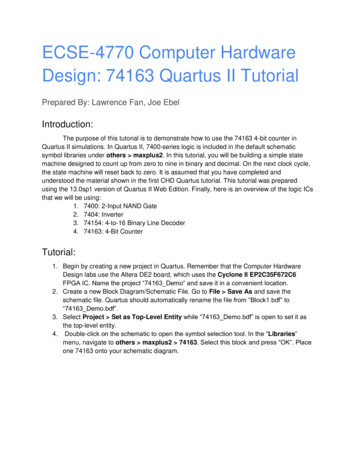
Create a Working DirectoryFirst of all, create a folder, for exampleC:\Users\your account\Documents\cod cpuYour all designs must be done in this folderlpdÓõ gÓ Quartus II A ModelSim G³ j – 2 / 31
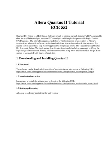
Start Quartus II 13.1Start Quartus II 13.1Choose Run the Quartus II softwareClick OKClose Home windowlpdÓõ gÓ Quartus II A ModelSim G³ j – 3 / 31
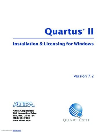
New Project — mux2x11Create a new project mux2x1 (1 bit)File New Project Wizard.Click Next 2lpdÓõ gÓ Quartus II A ModelSim G³ j – 4 / 31
Working Directory and Project Name12Input working directory and project nameWorking directory: The folder you created !!!Project name: mux2x1Click Finish3lpdÓõ gÓ Quartus II A ModelSim G³ j – 5 / 31
New Block Diagram/Schematic File12Open a circuit edit windowFile New3Select Block Diagram/Schematic FileClick OKlpdÓõ gÓ Quartus II A ModelSim G³ j – 6 / 31
Input GatesInput a component1Double-click inside the edit windowType and2 in Name field2Click OKlpdÓõ gÓ Quartus II A ModelSim G³ j – 7 / 31
Input Gates and PinsInput components: or2, not, input, outputYou can copy a component with mouse while pressing Ctrl keylpdÓõ gÓ Quartus II A ModelSim G³ j – 8 / 31
Assign Pin NamesChange the pin names to A0, A1, S, YSelect a pinDouble-click pin nameType the pin namePress Enter keylpdÓõ gÓ Quartus II A ModelSim G³ j – 9 / 31
Wiring1Use mouse to connect pins with wiresFile Save (Ctrl s)Click J5 (S)lpdÓõ gÓ Quartus II A ModelSim G³ j – 10 / 31
Start Analysis & Synthesis1Processing Start Start Analysis & Synthesis (Ctrl k)Revise the circuit if there are errorslpdÓõ gÓ Quartus II A ModelSim G³ j – 11 / 31
Create Verilog HDL Design File12Create Verilog HDL design file3File Create/Update Create HDL Design File from Current File.Choose Verilog HDLClick OKlpdÓõ gÓ Quartus II A ModelSim G³ j – 12 / 31
New Verilog HDL Testbench File12Open a text edit windowFile NewSelect Verilog HDL File3Click OKlpdÓõ gÓ Quartus II A ModelSim G³ j – 13 / 31
Code of Verilog HDL Testbench FileType code here (for simulation)Save it as mux2x1 tb.vlpdÓõ gÓ Quartus II A ModelSim G³ j – 14 / 31
Start ModelSim-Quartus 10.1d2Important: Change directory toC:\Users\your account\Documents\cod cpuStart ModelSim 10.1dClick Close to close Welcome windowChange directory to your working directoryFile Change Directory.1lpdÓõ gÓ Quartus II A ModelSim G³ j – 15 / 31
Compile mux2x1.v and mux2x1 tb.v12CompileCompile Compile.Select mux2x1.v and mux2x1 tb.v (pressing Shift key)Click CompilelpdÓõ gÓ 3Quartus II A ModelSim G³ j – 16 / 31
Create work DirectoryClick Yes to create “work” directoryClick Done to close compile window12lpdÓõ gÓ Quartus II A ModelSim G³ j – 17 / 31
Start Simulation1SimulateSimulate Start Simulation.Select mux2x1 tb.v2Click OK3lpdÓõ gÓ Quartus II A ModelSim G³ j – 18 / 31
Change Simulation Time to 100 ns21Set simulation time to 100 ns (default: 100 ps)View Transcript (Open Transcript window)lpdÓõ gÓ Quartus II A ModelSim G³ j – 19 / 31
Add Signals to Wave Window1Type add wave /*lpdÓõ gÓ Quartus II A ModelSim G³ j – 20 / 31
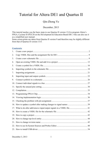
Run Simulation1Type runIn Wave window, you can change the view of waveformFrom the waveform we can check the correctness of the multiplexer:if (S 0) Y A0;elseY A1;lpdÓõ gÓ Quartus II A ModelSim G³ j – 21 / 31
Create Block Symbol for Future Use21Open Quartus window3Create block symbolSelect schematic window mux2x1.bdfFile Create/Update Create Symbol Files for Current FileClick OKProject mux2x1 finished. Congratulations!lpdÓõ gÓ Quartus II A ModelSim G³ j – 22 / 31
New Project — mux2x81Create a new project mux2x8 (8 bits)File New Project Wizard.2Do you want to close current project "mux2x1"? YesProject directory . Do you want to select a different project directory? NolpdÓõ gÓ Quartus II A ModelSim G³ j – 23 / 31
Input ComponentslpdÓõ gÓ Quartus II A ModelSim G³ j – 24 / 31
Use Wire Names to Connect PinslpdÓõ gÓ Quartus II A ModelSim G³ j – 25 / 31
Start Analysis & Synthesis12Processing Start Start Analysis & Synthesis (Ctrl k)Click Flow MessageThere are WarningslpdÓõ gÓ Quartus II A ModelSim G³ j – 26 / 31
Add Project mux2x1.bdf12Project Add/Remove Files in Project.Add project mux2x1.bdflpdÓõ gÓ Quartus II A ModelSim G³ j – 27 / 31
Start Analysis & Synthesis12Processing Start Start Analysis & Synthesis (Ctrl k)Click Flow MessagelpdÓõ gÓ Quartus II A ModelSim G³ j – 28 / 31
Code of Testbench File mux2x8 tb.vCreate Verilog HDL design filesSelect Schematic Window mux2x8.bdfFile Create/Update Create HDL Design File from Current File.Create new Verilog HDL testbench filelpdÓõ gÓ Quartus II A ModelSim G³ j – 29 / 31
Simulation with ModelSimlpdÓõ gÓ Quartus II A ModelSim G³ j – 30 / 31
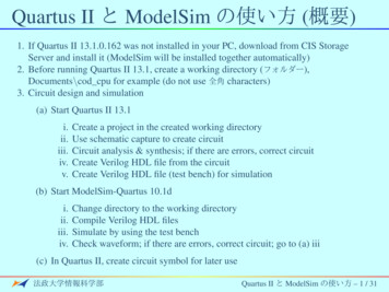
Create Block Symbol for Future Use21Open Quartus windowCreate block symbolSelect Schematic Window mux2x8.bdfFile Create/Update Create Symbol Files for Current FileClick OK3Project mux2x8 finished. Congratulations!lpdÓõ gÓ Quartus II A ModelSim G³ j – 31 / 31
Quartus II A ModelSim G³ j ( ) 1. If Quartus II 13.1.0.162 was not installed in your PC, download from CIS Storage Server and install it (ModelSim will be installed together automatically) 2. Before running Quartus II 13.1, create a working directory (), Documents\cod_cpu for example (do not use ÓÌ characters) 3. Circuit design and .