Transcription
ECSE-4770 Computer HardwareDesign: 74163 Quartus II TutorialPrepared By: Lawrence Fan, Joe EbelIntroduction:The purpose of this tutorial is to demonstrate how to use the 74163 4-bit counter inQuartus II simulations. In Quartus II, 7400-series logic is included in the default schematicsymbol libraries under others maxplus2. In this tutorial, you will be building a simple statemachine designed to count up from zero to nine in binary and decimal. On the next clock cycle,the state machine will reset back to zero. It is assumed that you have completed andunderstood the material shown in the first CHD Quartus tutorial. This tutorial was preparedusing the 13.0sp1 version of Quartus II Web Edition. Finally, here is an overview of the logic ICsthat we will be using:1. 7400: 2-Input NAND Gate2. 7404: Inverter3. 74154: 4-to-16 Binary Line Decoder4. 74163: 4-Bit CounterTutorial:1. Begin by creating a new project in Quartus. Remember that the Computer HardwareDesign labs use the Altera DE2 board, which uses the Cyclone II EP2C35F672C6FPGA IC. Name the project “74163 Demo” and save it in a convenient location.2. Create a new Block Diagram/Schematic File. Go to File Save As and save theschematic file. Quartus should automatically rename the file from “Block1.bdf” to“74163 Demo.bdf”.3. Select Project Set as Top-Level Entity while “74163 Demo.bdf” is open to set it asthe top-level entity.4. Double-click on the schematic to open the symbol selection tool. In the “Libraries”menu, navigate to others maxplus2 74163. Select this block and press “OK”. Placeone 74163 onto your schematic diagram.
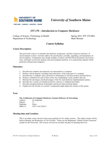
Figure 1: 74163 Counter5. Some things to note about the 74163:a. The LDN line is an active-low input that causes the 74163 to load a 4-bit valuefrom the lines A, B, C, D into the internal memory of the counter.b. A, B, C, D are the active-high input lines that the counter loads from.c. ENT and ENP are active-high enable lines.d. CLRN is the active-low clear line to zero the counter’s value. We will not be usingit in this tutorial, opting to load a zero value instead. The load value can be easilychanged to start the counter at a non-zero value.e. CLK is a rising-edge triggered input that causes the counter to increment itsinternal value by one.f. QA, QB, QC, QD are active-high outputs representing the binary value of thecounter’s internal state.g. RCO is an active-high output that is useful for chaining multiple 74163s into a 4nbit counter.6. In the symbol selection tool, go to primitives other gnd to insert a ground. Place theground near the input side of the 74163. Connect A, B, C, and D to the ground with wiresusing the Orthogonal Node Tool.Figure 2: Load input lines pulled down to ground
7. In the symbol selection tool, insert a VCC symbol. It is located in the same folder as theGND symbol. Connect the ENT, ENP, and CLRN lines to the VCC symbol to tie them tothe high rail of this circuit.Figure 3: ENT, ENP, CLRN pulled high to VCC8. In the symbol selection tool, navigate to primitives pin input to select the input pinsymbol. Place an input near the CLK line of the 74163 and wire it to CLK. The pin willinitially have a default name. Double-click on the name to select it and type in “CLK IN”.Press the “Enter” key to rename the pin.Figure 4: CLK IN input pin attached to CLK input of 741639. We want our state machine to reset after it reaches State 9. Therefore, we shouldimplement some logic to detect this state, which occurs at DCBA 1001. The simplestway to do this is by using a 2-input AND gate connected to QD and QA. Because theload input is active-low, we need to invert the gate output, thereby making it a NANDgate. The 2-input NAND gate is the first 7400-series IC, and can be found at others maxplus2 7400. Place a 7400 above the 74163 and connect its inputs to QD and QA.Connect its output to LDN. You will notice that the 7400, when first placed, is in aninconvenient orientation. Select the gate and press the “Flip Horizontal” button on the
toolbar above the schematic view.Figure 5: 2-input NAND gate connected to 7416310. Now, we will insert the 4-to-16 decoder. Open the symbol selector and navigate toothers maxplus2 74154. Place a 74154 below and to the right of the 74163.Figure 6: State machine and decoder11. Some things to note about the 74154:a. The four binary inputs are A, B, C, D.b. G1N and G2N are both active-low enable lines.c. O0-O16 are the sixteen active-low decimal output lines. These will be enabledone at a time to represent the decimal value of the binary input value.
12. Place another GND symbol close to G1N and G2N of the decoder. Connect G1N andG2N to the ground.Figure 7: 4-to-16 decoder with enable lines tied low.13. We can simplify and clean up our circuit by using busses to represent multi-bit or parallelsignals. In this case, we should connect the 4-bit DCBA line from the 74163 to the 74154using a bus. In the toolbar, select the Orthogonal Bus Tool. It is directly adjacent to thewire tool that we have previously been using.Figure 8: Multi-line bus between the counter and the decoder14. Use the Orthogonal Node Tool to connect QA, QB, QC, and QD on the counter, as wellas A, B, C, and D on the decoder, to the bus.
Figure 9: Multi-line bus connecting counter to decoder15. In order to tell Quartus which wires should connect together, we need to name them.Name the line between QA and A “SM A”, and repeat likewise for the rest of the lines.Name a wire by selecting it and right-clicking to bring up a menu. Select “Properties” tobring up the Node Properties menu. Enter a name into the “Name” text box and press“OK”.Figure 10: All input lines and output lines connected to bus have been named16. The 74154 has active-low outputs, so we have to use inverters to get an active-highoutput. Select the 7404 inverter at others maxplus2 7404 and place ten inverters atthe first ten outputs of the 74154. Connect them to O0-O9 of the 74154. There is a bug
where the first inverter you place may not be named correctly. If it has the name “inst”instead of “instx” where x is a number, place it somewhere else and then place the restof the inverters. Go back and delete the improperly-named inverter after everything elseis wired.Figure 11: Ten 7404 inverters placed at the active-low outputs of the 74154 decoder. Note theinverter name bug at the output of O1N.17. Navigate to primitives pin output in the symbol selection window to select anoutput pin. Place ten output pins near the inverters. Wire each inverter output to itscorresponding output pin. Name each output pin. In this case, I named them “ZERO”through “NINE”.Figure 12: Ten named output pins connected to the inverted outputs of the 74154
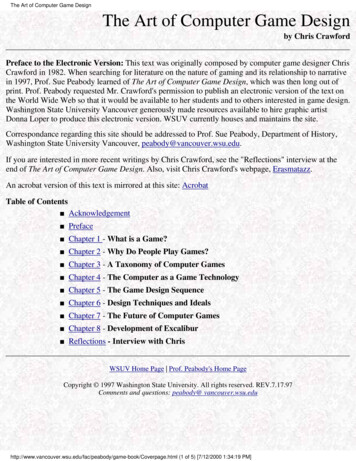
18. Please check your schematic against this one:Figure 13: Final Schematic19. Go to Processing Start Compilation and compile your schematic.Figure 14: Output of successful compilation20. Go to File New and create a new University Program VWF. This option is under“Verification/Debugging Files”. Right-click on the bar in the left side of the screen tobring up a menu. Select “Insert Node or Bus. . .”. In the window that opens, select“Node Finder. . .” and switch to the Node Finder window. Click the “List” button toimport all I/O nodes from the schematic and press the double chevron button “ ” toimport all nodes. Press “OK” on the Node Finder and “OK” on the “Insert Node or Bus”to finish.
Figure 15: Importing all I/O nodes21. The box on the left side of the window will have the nodes out of order. Click and dragthe signals up and down to rearrange them. The solid line next to CLK IN representsthat it is a controllable input line. The hatched lines next to the other signals representsthat they are uncalculated outputs.Figure 16: Timing Diagram22. You can set input values by clicking and dragging to select a piece of a line and thenpressing the ‘1’ or ‘0’ buttons to set the value of that section of the line. Make a simplesquare wave with ten pulses.Figure 17: Timing Diagram with input set23. Go to Simulation Options and set the simulator to “Quartus II Simulator”. This willhave to be done every time this waveform file is opened. The program will open awarning dialog box. Press “OK” to ignore it. Then, go to Simulation Run FunctionalSimulation in order to simulate the circuit behavior. The program will ask you to savethe waveform file. Then, the simulation results will open up in a separate window.
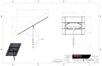
24. Check your results against the sample results:Figure 18: Computed Timing DiagramNote that the circuit output is active-high and the input is rising-edge triggered asexpected. The circuit starts in State 0, and on each rising edge of the input clock, itadvances to the next state, until it reaches State 9. At that point, on the next rising edge,the state machine resets to State 0.25. We will now go through the steps to download the design to the DE2 board. First, wemust tell Quartus what physical pins on the FPGA it must assign the input and outputsignals to. After closing the simulation windows, select Assignments Pin Planner fromthe menu to open up the pin planner shown below:
26. You will notice that there are already pins assigned in the “Fitter Location” column.These were automatically assigned by the auto-fitter when we compiled the designbecause we did not specify any. In order to assign our own pins, we will enter the pinname in the “Location” column. The pin numbers for all of the peripherals on the DE2board can be found in the user manual:ftp://ftp.altera.com/up/pub/Webdocs/DE2 UserManual.pdfDouble click the Location box for each node and enter the corresponding pinassignments for switch (0) and red LEDs (0-7). The pins for items can be found in tables4.1 and 4.3 on pages 28 and 29 of the user manual.27. Close the pin planner and compile the design again by selecting Processing StartCompilation from the menu.28. To prepare the DE2 board to run the program, connect the 9V power adapter to theconnector in the upper-left hand corner of the board. Connect a USB cable from yourcomputer to the USB connector labelled “BLASTER” located immediately next to thepower connector. When the board is powered, a welcome message will appear on theLCD screen and LEDs will flash. If the board does not turn on, ensure the red powerswitch (SW18) near the power connector is depressed.29. Once the design has been successfully compiled, select Tools Programmer from themenu to open the programmer tool shown below.
30. Press the “Hardware Setup ” button to open the window below. Under currentlyselected hardware, select USB-Blaster (USB-Blaster will not appear if the driver is notinstalled or if the USB cable is not connected properly). Upon closing the HardwareSetup window, the USB-Blaster will appear as the selected hardware in the Programmerwindow.31. Now the “Start” button should be enabled. Press this button to program your design tothe DE2 board. Note that the program will be erased whenever power to the DE2 boardis lost.Miscellaneous Quartus II Tips:a. Connecting pins using wires in Quartus II schematics requires superhuman precision.You will often make mistakes that lead to unconnected pins or extra wiring. When thishappens, press CTRL Z to undo the wire and then try again. When you finish wiring,carefully look over your schematic for the small ‘x’ symbol that represents anunconnected pin or wire.b. Double-check that your selected device is the EP2C35F672C6 in the Cyclone II family.If you select a different FPGA, Quartus will still compile and it may load to the DE2board. However, it will not work.c. During simulations, make sure that the “Quartus II Simulator” is selected. The programwill reset this to “ModelSim” every time you close and reopen the waveform file.d. If you are using the MalwareBytes Antivirus software on your computer, add “C:\altera”to the antivirus exclusion list. Otherwise, the AV’s heuristic detection engine may flagQuartus as malware and corrupt your installation.Installing USB-Blaster Driver:a. Open Device Manager and find the USB-Blaster.b. Right-click and select update driver.c. Select Browse my computer for driver software and search this erd. Continue and complete the installation (Windows may warn that it cannot verify thepublisher, proceed with the installation anyway).
Design: 74163 Quartus II Tutorial Prepared By: Lawrence Fan, Joe Ebel Introduction: The purpose of this tutorial is to demonstrate how to use the 74163 4-bit counter in Quartus II simulations. In Quartus II, 7400-series logic is included in the default schematic symbol libraries under others &g