Transcription
Quartus Prime IntroductionUsing VHDL DesignsFor Quartus Prime 18.1Contents1Introduction22Background33Getting Started43.1Quartus Prime Online Help . . . . . . . . . . . . . . . . . . . . . . . . . . . . . . . . . . . . . . . . . . . . . . . . . . . . . . . . . . . . . . . . . . . . . . . . . . . . . . . . . . . . . . . . . . . . . . . .64Starting a New Project5Design Entry Using VHDL Code135.1Using the Quartus Prime Text Editor . . . . . . . . . . . . . . . . . . . . . . . . . . . . . . . . . . . . . . . . . . . . . . . . . . . . . . . . . . . . . . . . . . . . . . . . . . . . . . . . . . . . . . . . . . . .145.1.1Using VHDL Templates . . . . . . . . . . . . . . . . . . . . . . . . . . . . . . . . . . . . . . . . . . . . . . . . . . . . . . . . . . . . . . . . . . . . . . . . . . . . . . . . . . . . . . . . . . . . . .16Adding Design Files to a Project . . . . . . . . . . . . . . . . . . . . . . . . . . . . . . . . . . . . . . . . . . . . . . . . . . . . . . . . . . . . . . . . . . . . . . . . . . . . . . . . . . . . . . . . . . . . . .165.266Compiling the Designed Circuit186.119Errors . . . . . . . . . . . . . . . . . . . . . . . . . . . . . . . . . . . . . . . . . . . . . . . . . . . . . . . . . . . . . . . . . . . . . . . . . . . . . . . . . . . . . . . . . . . . . . . . . . . . . . . . . . . . .7Pin Assignment228Programming and Configuring the FPGA Device268.1JTAG* Programming for the DE0-CV, DE0-Nano, DE10-Lite, and DE2-115 Boards . . . . . . . . . . . . . . . . . . . . . . . . . . . . . . . . . . . . . . . . . . . . . . . . . . . . . . . . . . . . . . . .268.2JTAG* Programming for the DE0-Nano-SoC, DE1-SoC Board, DE10-Nano, and DE10-Standard . . . . . . . . . . . . . . . . . . . . . . . . . . . . . . . . . . . . . . . . . . . . . . . . . . . . . . . . .289Testing the Designed CircuitIntel Corporation - FPGA University ProgramMarch 2019301
Q UARTUS P RIME I NTRODUCTION U SING VHDL D ESIGNS1For Quartus Prime 18.1IntroductionThis tutorial presents an introduction to the Quartus Prime CAD system. It gives a general overview of a typicalCAD flow for designing circuits that are implemented by using FPGA devices, and shows how this flow is realizedin the Quartus Prime software. The design process is illustrated by giving step-by-step instructions for using theQuartus Prime software to implement a very simple circuit in an Intel FPGA device.The Quartus Prime system includes full support for all of the popular methods of entering a description of the desiredcircuit into a CAD system. This tutorial makes use of the VHDL design entry method, in which the user specifies thedesired circuit in the VHDL hardware description language. Three versions of this tutorial are available; one usesthe Verilog hardware description language, another uses the VHDL hardware description language, and the third isbased on defining the desired circuit in the form of a schematic diagram.The last step in the design process involves configuring the designed circuit in an actual FPGA device. To show howthis is done, it is assumed that the user has access to the Intel DE-series Development and Education board connectedto a computer that has Quartus Prime software installed. A reader who does not have access to the DE-series boardwill still find the tutorial useful to learn how the FPGA programming and configuration task is performed.The screen captures in the tutorial were obtained using the Quartus Prime version 18.1 Standard Edition; otherversions of the software may be slightly different.2Intel Corporation - FPGA University ProgramMarch 2019
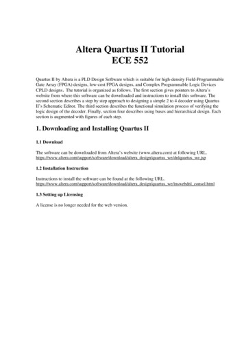
Q UARTUS P RIME I NTRODUCTION U SING VHDL D ESIGNS2For Quartus Prime 18.1BackgroundComputer Aided Design (CAD) software makes it easy to implement a desired logic circuit by using a programmablelogic device, such as a Field-Programmable Gate Array (FPGA) chip. A typical FPGA CAD flow is illustrated inFigure 1.Figure 1. Typical CAD flow.The CAD flow involves the following steps: Design Entry – the desired circuit is specified either by means of a schematic diagram, or by using a hardwaredescription language, such as Verilog or VHDL Synthesis – the entered design is synthesized into a circuit that consists of the logic elements (LEs) providedin the FPGA chip Functional Simulation – the synthesized circuit is tested to verify its functional correctness; this simulationdoes not take into account any timing issuesIntel Corporation - FPGA University ProgramMarch 20193
Q UARTUS P RIME I NTRODUCTION U SING VHDL D ESIGNSFor Quartus Prime 18.1 Fitting – the CAD Fitter tool determines the placement of the LEs defined in the netlist into the LEs in anactual FPGA chip; it also chooses routing wires in the chip to make the required connections between specificLEs Timing Analysis – propagation delays along the various paths in the fitted circuit are analyzed to provide anindication of the expected performance of the circuit Timing Simulation – the fitted circuit is tested to verify both its functional correctness and timing Programming and Configuration – the designed circuit is implemented in a physical FPGA chip by programming the configuration switches that configure the LEs and establish the required wiring connectionsThis tutorial introduces the basic features of the Quartus Prime software. It shows how the software can be used todesign and implement a circuit specified by using the VHDL hardware description language. It makes use of thegraphical user interface to invoke the Quartus Prime commands. Doing this tutorial, the reader will learn about: Creating a project Design entry using VHDL code Synthesizing a circuit specified in VHDL code Fitting a synthesized circuit into an Intel FPGA Assigning the circuit inputs and outputs to specific pins on the FPGA Simulating the designed circuit Programming and configuring the FPGA chip on Intel’s DE-series board3Getting StartedEach logic circuit, or subcircuit, being designed with Quartus Prime software is called a project. The software workson one project at a time and keeps all information for that project in a single directory (folder) in the file system. Tobegin a new logic circuit design, the first step is to create a directory to hold its files. To hold the design files for thistutorial, we will use a directory introtutorial. The running example for this tutorial is a simple circuit for two-waylight control.Start the Quartus Prime software. You should see a display similar to the one in Figure 2. This display consistsof several windows that provide access to all the features of Quartus Prime software, which the user selects withthe computer mouse. Most of the commands provided by Quartus Prime software can be accessed by using a setof menus that are located below the title bar. For example, in Figure 2 clicking the left mouse button on the menunamed File opens the menu shown in Figure 3. Clicking the left mouse button on the entry Exit exits from QuartusPrime software. In general, whenever the mouse is used to select something, the left button is used. Hence we willnot normally specify which button to press. In the few cases when it is necessary to use the right mouse button, itwill be specified explicitly.4Intel Corporation - FPGA University ProgramMarch 2019
Q UARTUS P RIME I NTRODUCTION U SING VHDL D ESIGNSFor Quartus Prime 18.1Figure 2. The main Quartus Prime display.Figure 3. An example of the File menu.Intel Corporation - FPGA University ProgramMarch 20195
Q UARTUS P RIME I NTRODUCTION U SING VHDL D ESIGNSFor Quartus Prime 18.1For some commands it is necessary to access two or more menus in sequence. We use the convention Menu1 Menu2 Item to indicate that to select the desired command the user should first click the left mouse button onMenu1, then within this menu click on Menu2, and then within Menu2 click on Item. For example, File Exituses the mouse to exit from the system. Many commands can be invoked by clicking on an icon displayed in one ofthe toolbars. To see the command associated with an icon, position the mouse over the icon and the command namewill be shown in the status bar at the bottom of the screen.3.1Quartus Prime Online HelpQuartus Prime software provides comprehensive online documentation that answers many of the questions that mayarise when using the software. The documentation is accessed from the Help menu. To get some idea of the extentof documentation provided, it is worthwhile for the reader to browse through the Help menu.The user can quickly search through the Help topics by using the search box in the top right corner of the mainQuartus display. Another method, context-sensitive help, is provided for quickly finding documentation for specifictopics. While using most applications, pressing the F1 function key on the keyboard opens a Help display that showsthe commands available for the application.4Starting a New ProjectTo start working on a new design we first have to define a new design project. Quartus Prime software makes thedesigner’s task easy by providing support in the form of a wizard. Create a new project as follows:1. Select File New Project Wizard and click Next to reach the window in Figure 4, which asks for the nameand directory of the project.2. Set the working directory to be introtutorial; of course, you can use some other directory name of your choiceif you prefer. The project must have a name, which is usually the same as the top-level design entity that willbe included in the project. Choose light as the name for both the project and the top-level entity, as shownin Figure 4. Press Next. Since we have not yet created the directory introtutorial, Quartus Prime softwaredisplays the pop-up box in Figure 5 asking if it should create the desired directory. Click Yes, which leads tothe window in Figure 6.6Intel Corporation - FPGA University ProgramMarch 2019
Q UARTUS P RIME I NTRODUCTION U SING VHDL D ESIGNSFor Quartus Prime 18.1Figure 4. Creation of a new project.Figure 5. Quartus Prime software can create a new directory for the project.Intel Corporation - FPGA University ProgramMarch 20197
Q UARTUS P RIME I NTRODUCTION U SING VHDL D ESIGNSFor Quartus Prime 18.1Figure 6. Choosing the project type.3. The Project Type window, shown in Figure 6, allows you to choose from the Empty project and the Projecttemplate options. For this tutorial, choose Empty project as we will be creating a project from scratch, andpress Next which leads to the window in Figure 7.8Intel Corporation - FPGA University ProgramMarch 2019
Q UARTUS P RIME I NTRODUCTION U SING VHDL D ESIGNSFor Quartus Prime 18.1Figure 7. The wizard can include user-specified design files.4. The wizard makes it easy to specify which existing files (if any) should be included in the project. Assumingthat we do not have any existing files, click Next, which leads to the window in Figure 8.Intel Corporation - FPGA University ProgramMarch 20199
Q UARTUS P RIME I NTRODUCTION U SING VHDL D ESIGNSFor Quartus Prime 18.1Figure 8. Choose the device family and a specific device.5. We have to specify the type of device in which the designed circuit will be implemented. Choose the Cyclone series device family for your DE-series board. We can let Quartus Prime software select a specific device inthe family, or we can choose the device explicitly. We will take the latter approach. From the list of availabledevices, choose the appropriate device name for your DE-series board. A list of devices names on DE-seriesboards can be found in Table 1. Press Next, which opens the window in Figure 9.10Intel Corporation - FPGA University ProgramMarch 2019
Q UARTUS P RIME I NTRODUCTION U SING VHDL D 5DE10-LiteDE10-StandardDE10-NanoFor Quartus Prime 18.1Device NameCyclone V 5CEBA4F23C7Cyclone IVE EP4CE22F17C6Cyclone V SoC 5CSEMA4U23C6Cyclone V SoC 5CSEMA5F31C6Cyclone IVE EP4CE115F29C7Max 10 10M50DAF484C7GCyclone V SoC 5CSXFC6D6F31C6Cyclone V SE 5CSEBA6U2317Table 1. DE-series FPGA device namesFigure 9. Other EDA tools can be specified.6. The user can specify any third-party tools that should be used. A commonly used term for CAD software forelectronic circuits is EDA tools, where the acronym stands for Electronic Design Automation. This term isused in Quartus Prime messages that refer to third-party tools, which are the tools developed and marketed bycompanies other than Intel. Since we will rely solely on Quartus Prime tools, we will not choose any othertools. Press Next.Intel Corporation - FPGA University ProgramMarch 201911
Q UARTUS P RIME I NTRODUCTION U SING VHDL D ESIGNSFor Quartus Prime 18.17. A summary of the chosen settings appears in the screen shown in Figure 10. Press Finish, which returns tothe main Quartus Prime window, but with light specified as the new project, in the title bar, as indicated inFigure 11.Figure 10. Summary of project settings.12Intel Corporation - FPGA University ProgramMarch 2019
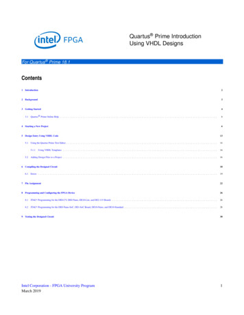
Q UARTUS P RIME I NTRODUCTION U SING VHDL D ESIGNSFor Quartus Prime 18.1Figure 11. The Quartus Prime window for a created project.5Design Entry Using VHDL CodeAs a design example, we will use the two-way light controller circuit shown in Figure 12. The circuit can be usedto control a single light from either of the two switches, x 1 and x 2 , where a closed switch corresponds to the logicvalue 1. The truth table for the circuit is also given in the figure. Note that this is just the Exclusive-OR function ofthe inputs x 1 and x 2 , but we will specify it using the gates shown.Figure 12. The light controller circuit.Intel Corporation - FPGA University ProgramMarch 201913
Q UARTUS P RIME I NTRODUCTION U SING VHDL D ESIGNSFor Quartus Prime 18.1The required circuit is described by the VHDL code in Figure 13. Note that the VHDL entity is called light to matchthe name given in Figure 4, which was specified when the project was created. This code can be typed into a fileby using any text editor that stores ASCPrime files, or by using the Quartus Prime text editing facilities. While thefile can be given any name, it is a common designers’ practice to use the same name as the name of the top-levelVHDL entity. The file name must include the extension vhd , which indicates a VHDL file. So, we will use thename light.vhd.LIBRARY ieee ;USE ieee.std logic 1164.all ;ENTITY light ISPORT(x1, x2 : INf: OUTEND light ;STD LOGIC ;STD LOGIC);ARCHITECTURE LogicFunction OF light ISBEGINf (x1 AND NOT x2) OR (NOT x1 AND x2) ;END LogicFunction ;Figure 13. VHDL code for the circuit in Figure 11.5.1Using the Quartus Prime Text EditorThis section shows how to use the Quartus Prime Text Editor. You can skip this section if you prefer to use someother text editor to create the VHDL source code file, which we will name light.vhd.Select File New to get the window in Figure 14, choose VHDL File, and click OK. This opens the Text Editorwindow. The first step is to specify a name for the file that will be created. Select File Save As to open the pop-upbox depicted in Figure 15. In the box labeled Save as type choose VHDL File. In the box labeled File name typelight. Put a checkmark in the box Add file to current project. Click Save, which puts the file into the directoryintrotutorial and leads to the Text Editor window shown in Figure 16. Enter the VHDL code in Figure 13 into theText Editor and save the file by typing File Save, or by typing the shortcut Ctrl-s.Most of the commands available in the Text Editor are self-explanatory. Text is entered at the insertion point, whichis indicated by a thin vertical line. The insertion point can be moved either by using the keyboard arrow keys or byusing the mouse. Two features of the Text Editor are especially convenient for typing VHDL code. First, the editorcan display different types of VHDL statements in different colors, which is the default choice. Second, the editorcan automatically indent the text on a new line so that it matches the previous line. Such options can be controlledby the settings in Tools Options Text Editor.14Intel Corporation - FPGA University ProgramMarch 2019
Q UARTUS P RIME I NTRODUCTION U SING VHDL D ESIGNSFor Quartus Prime 18.1Figure 14. Choose to prepare a VHDL file.Figure 15. Name the file.Intel Corporation - FPGA University ProgramMarch 201915
Q UARTUS P RIME I NTRODUCTION U SING VHDL D ESIGNSFor Quartus Prime 18.1Figure 16. Text Editor window.5.1.1Using VHDL TemplatesThe syntax of VHDL code is sometimes difficult for a designer to remember. To help with this issue, the Text Editorprovides a collection of VHDL templates. The templates provide examples of various types of VHDL statements,such as an ENTITY declaration, a CASE statement, and assignment statements. It is worthwhile to browse throughthe templates by selecting Edit Insert Template VHDL to become familiar with this resource.5.2Adding Design Files to a ProjectAs we indicated when discussing Figure 7, you can tell Quartus Prime software which design files it should useas part of the current project. To see the list of files already included in the light project, select Assignments Settings, which leads to the window in Figure 17. As indicated on the left side of the figure, click on the item Files.An alternative way of making this selection is to choose Project Add/Remove Files in Project.If you used the Quartus Prime Text Editor to create the file and checked the box labeled Add file to current project,as described in Section 5.1, then the light.vhd file is already a part of the project and will be listed in the window in16Intel Corporation - FPGA University ProgramMarch 2019
Q UARTUS P RIME I NTRODUCTION U SING VHDL D ESIGNSFor Quartus Prime 18.1Figure 17. Otherwise, the file must be added to the project. So, if you did not use the Quartus Prime Text Editor, thenplace a copy of the file light.vhd, which you created using some other text editor, into the directory introtutorial. Toadd this file to the project, click on the . button next to the box labelled File name in Figure 17 to get the pop-upwindow in Figure 18. Select the light.vhd file and click Open. The selected file is now indicated in the File namebox in of Figure 17. Click Add then OK to include the light.vhd file in the project. We should mention that in manycases the Quartus Prime software is able to automatically find the right files to use for each entity referenced inVHDL code, even if the file has not been explicitly added to the project. However, for complex projects that involvemany files it is a good design practice to specifically add the needed files to the project, as described above.Figure 17. Settings window.Intel Corporation - FPGA University ProgramMarch 201917
Q UARTUS P RIME I NTRODUCTION U SING VHDL D ESIGNSFor Quartus Prime 18.1Figure 18. Select the file.6Compiling the Designed CircuitThe VHDL code in the file light.vhd is processed by several Quartus Prime tools that analyze the code, synthesizethe circuit, and generate an implementation of it for the target chip. These tools are controlled by the applicationprogram called the Compiler.Run the Compiler by selecting Processing Start Compilation, or by clicking on the toolbar iconthat lookslike a purple triangle. Your project must be saved before compiling. As the compilation moves through variousstages, its progress is reported in a window on the left side of the Quartus Prime display. In the message window, atthe bottom of the figure, various messages are displayed throughout the compilation process. In case of errors, therewill be appropriate messages given.When the compilation is finished, a compilation report is produced. A tab showing this report is opened automatically, as seen in Figure 21. The tab can be closed in the normal way, and it can be opened at any time either byselecting Processing Compilation Report or by clicking on the icon . The report includes a number of sectionslisted on the left side. Figure 21 displays the Compiler Flow Summary section, which indicates that only one logicelement and three pins are needed to implement this tiny circuit on the selected FPGA chip.18Intel Corporation - FPGA University ProgramMarch 2019
Q UARTUS P RIME I NTRODUCTION U SING VHDL D ESIGNSFor Quartus Prime 18.1Figure 19. Display after a successful compilation.6.1ErrorsQuartus Prime software displays messages produced during compilation in the Messages window. If the VHDLdesign file is correct, one of the messages will state that the compilation was successful and that there are no errors.If the Compiler does not report zero errors, then there is at least one mistake in the VHDL code. In this casea message corresponding to each error found will be displayed in the Messages window. Double-clicking on anerror message will highlight the offending statement in the VHDL code in the Text Editor window. Similarly, theCompiler may display some warning messages. Their details can be explored in the same way as in the case of errormessages. The user can obtain more information about a specific error or warning message by selecting the messageand pressing the F1 function key.To see the effect of an error, open the file light.vhd. Remove the semicolon in the statement that defines the functionf, illustrating a typographical error that is easily made. Compile the erroneous design file by clicking on theicon. A pop-up box will ask if the changes made to the light.vhd file should be saved; click Yes. After trying tocompile the circuit, Quartus Prime software will display error messages in the Messages window, and show that thecompilation failed in the Analysis & Synthesis stage of the compilation process. The compilation report summary,given in Figure 20, confirms the failed result. In the Table of Contents panel, expand the Analysis & Synthesis partIntel Corporation - FPGA University ProgramMarch 201919
Q UARTUS P RIME I NTRODUCTION U SING VHDL D ESIGNSFor Quartus Prime 18.1of the report and then select Messages to have the messages displayed as shown in Figure 21. The CompilationReport can be dispayed as a separate window as in Figure 21 by right-clicking its tab and selecting Detach Window,and can be reattached by clicking Window Attach Window. Double-click on the first error message. QuartusPrime software responds by opening the light.vhd file and highlighting the statement which is affected by the error,as shown in Figure 22. Correct the error and recompile the design.Figure 20. Compilation report for the failed design.20Intel Corporation - FPGA University ProgramMarch 2019
Q UARTUS P RIME I NTRODUCTION U SING VHDL D ESIGNSFor Quartus Prime 18.1Figure 21. Error messages.Figure 22. Identifying the location of the error.Intel Corporation - FPGA University ProgramMarch 201921
Q UARTUS P RIME I NTRODUCTION U SING VHDL D ESIGNS7For Quartus Prime 18.1Pin AssignmentDuring the compilation above, the Quartus Prime Compiler was free to choose any pins on the selected FPGA toserve as inputs and outputs. However, the DE-series board has hardwired connections between the FPGA pins andthe other components on the board. We will use two toggle switches, labeled SW0 and SW1 , to provide the externalinputs, x 1 and x 2 , to our example circuit. These switches are connected to the FPGA pins listed in Table 2. We willconnect the output f to a light-emitting diode on your DE-series board. For the DE2-115 we will use a green LED:LE DG 0 . On the DE0-CV, DE1-SoC, DE-10 Lite and DE10-Standard we will use LE DR 0 . On the DE0-Nano andDE0-Nano-SoC, we will use LE D 0 The FPGA pin assignment for the LEDs can also be found in Table CDE10-LiteDE10-StandardDE10-NanoSW0SW1PIN U13PIN M1PIN L10PIN AB28PIN AB12PIN C10PIN AB30PIN Y24PIN V13PIN T8PIN L9PIN AC28PIN AC12PIN C11PIN AB28PIN W24LEDG0 , LED0 , or LEDR0PIN AA2PIN A1PIN W15PIN E21PIN V16PIN A8PIN AA24PIN W15Table 2. DE-Series Pin AssignmentsFigure 23. The Assignment Editor window.Pin assignments are made by using the Assignment Editor. Select Assignments Assignment Editor to reach thewindow in Figure 23 (shown here as a detached window). In the Category drop-down menu select All. Click onthe new button located near the top left corner to make a new item appear in the table. Double click the box22Intel Corporation - FPGA University ProgramMarch 2019
Q UARTUS P RIME I NTRODUCTION U SING VHDL D ESIGNSFor Quartus Prime 18.1under the column labeled To so that the Node Finder buttonappears. Click on the button (not the drop downarrow) to reach the window in Figure 24. Click onandto show or hide more search options. In the Filterdrop-down menu select Pins: all. Then click the List button to display the input and output pins to be assigned: f ,x1, and x2. Click on x1 as the first pin to be assigned and click the button; this will enter x1 in the Selected Nodesbox. Click OK. x1 will now appear in the box under the column labeled To. Alternatively, the node name can beentered directly by double-clicking the box under the To column and typing in the node name.Follow this by double-clicking on the box to the right of this new x1 entry, in the column labeled Assignment Name.Now, the drop-down menu in Figure 25 appears. Scroll down and select Location (Accepts wildcards/groups).Instead of scrolling down the menu to find the desired item, you can just type the first letter of the item in theAssignment Name box. In this case the desired item happens to be the first item beginning with L. Finally, doubleclick the box in the column labeled Value. Type the pin assignment corresponding to SW0 for your DE-series board,as listed in Table 2.Use the same procedure to assign input x2 and output f to the appropriate pins listed in Table 2. An exampleusing a DE1-SoC board is shown in Figure 26. To save the assignments made, choose File Save. You can alsosimply close the Assignment Editor window, in which case a pop-up box will ask if you want to save the changes toassignments; click Yes. Recompile the circuit, so that it will be compiled with the correct pin assignments.Figure 24. The Node Finder displays the input and output names.Intel Corporation - FPGA University ProgramMarch 201923
Q UARTUS P RIME I NTRODUCTION U SING VHDL D ESIGNSFor Quartus Prime 18.1Figure 25. The available assignment names for a DE-series board.Figure 26. The complete assignment.The DE-series board has fixed pin assignments. Having finished one design, the user will want to use the same pinassignment for subsequent designs. Going through the procedure described above becomes tedious if there are manypins used in the design. A useful Quartus Prime feature allows the user to both export and import the pin assignmentsfrom a special file format, rather than creating them manually using the Assignment Editor. A simple file format thatcan be used for this purpose is the Quartus Settings File (QSF) format. The format for the file for our simple project(on a DE1-SoC board) isset location assignment PIN AB12 -to x1set location assignment PIN AC12 -to x2set location assignment PIN V16 -to fBy adding lines to the file, any number of pin assignments can be created. Such qsf files can be imported into anydesign project.If you created a pin assignment for a particular project, you can export it for use in a different project. To see howthis is done, open again the Assignment Editor to reach the window in Figure 26. Select Assignments Export24Intel Corporation - FPGA University ProgramMarch 2019
Q UARTUS P RIME I NTRODUCTION U SING VHDL D ESIGNSFor Quartus Prime 18.1Assignment which leads to the window in Figure 27. Here, the file light.qsf is available for export. Click on OK. Ifyou now look in the directory, you will see that the file light.qsf has been created.Figure 27. Exporting the pin assignment.You can import a pin assignment by choosing Assignments Import Assignments. This opens the dialogue inFigure 28 to select the file to import. Type the name of the file, including the qsf extension and the full path to thedirectory that holds the file, in the File Name box and press OK. Of course, you can also browse to find the desiredfile.Figure 28. Importing the pin assignment.For convenience when using large designs, all relevant pin assignments for the DE-series board are given in individual files. For example, the DE1-SoC pin assignments can be found in the DE1 SoC.qsf file, which is availablefrom Intel’s FPGA University Program website. This file uses the names found in the DE1-SoC User Manual. Ifwe wanted to make the pin assignments for our example circuit by importing this file, then we would have to usethe same names in our Block Diagram/Schematic design file; namely, SW[0], SW[1] and LEDG[0] for x1, x2 andf, respectively. Since these signals are specified in the DE1 SoC.qsf file as elements of vectors SW and LEDG, wemust refer to them in the same way in our design file. For example, in the DE1 SoC.qsf file the 10 toggle switchesare called SW[9] to SW[0]. In a design file they can also be referred to as a vector SW[9.0].Intel Corporation - FPGA University ProgramMarch 201925
Q UARTUS P RIME I NTRODUCTION U SING VHDL D ESIGNS8For Quartus Prime 18.1Programming and Configuring the FPGA DeviceThe FPGA device must be programmed and configured to implement the designed circuit. The required configuration file is generated by the Quartus Prime Compiler’s Assembler module. Intel’s DE-series board allows theconfiguration to be done in two different ways, known as JTAG* and AS modes. The configuration data is transferred from the host computer (which runs the Quartus Prime software) to the board by means of a cable that connectsa USB port on the host computer to the USB-Blaster connector on the board. To use this connection, it is necessaryto have the USB-Blaster driver installed. If
QUARTUS PRIME INTRODUCTION USING VHDL DESIGNS For Quartus Prime 18.1 For some commands it is necessary to access two or more menus in sequence. We use the convention Menu1 Menu2 Item to indicate that to select the desired command the user should first click the left mouse button on Menu1, then within this menu click on Menu2, and then within Menu2 click on Item.