Transcription
Mike Holt’s Illustrated Guide toNEC REQUIREMENTS FOR GENERATORSAND STANDBY POWER SYSTEMS Based on the 2014 NEC Rule 220.87, Articles 445, 700, 701, and 702Extracted from Mike Holt’s Illustrated Guides to Understandingthe National Electrical Code Volumes 1 and 2For more information on this or other training products,visit www.MikeHolt.com or call 888.632.2633Date: March 16, 2015
NOTICE TO THE READERThe publisher does not warrant or guarantee any of theproducts described herein or perform any independentanalysis in connection with any of the product informationcontained herein. The publisher does not assume, andexpressly disclaims, any obligation to obtain and includeinformation other than that provided to it by the manufacturer.The reader is expressly warned to consider and adopt allsafety precautions that might be indicated by the activitiesherein and to avoid all potential hazards. By following theinstructions contained herein, the reader willingly assumesall risks in connection with such instructions.The publisher makes no representation or warranties ofany kind, including but not limited to, the warranties of fitness for particular purpose or merchantability, nor are anysuch representations implied with respect to the materialset forth herein, and the publisher takes no responsibilitywith respect to such material. The publisher shall not beliable for any special, consequential, or exemplary damages resulting, in whole or part, from the reader’s use of,or reliance upon, this material.Author: Mike HoltTechnical Illustrator: Mike CulbreathCOPYRIGHT 2015 Charles Michael HoltProduced and Printed in the USAAll rights reserved. No part of this work covered by thecopyright hereon may be reproduced or used in any form orby any means graphic, electronic, or mechanical, includingphotocopying, recording, taping, or information storageand retrieval systems without the written permission ofthe publisher. You can request permission to use materialfrom this text by either calling 888.632.2633, e-mailingInfo@MikeHolt.com, or visiting www.MikeHolt.com.ABOUT THE AUTHORMike Holt worked his way upthrough the electrical trade. Hebegan as an apprentice electricianand became one of the mostrecognized experts in the worldas it relates to electrical powerinstallations. He’s worked asa journeyman electrician,master electrician, and electrical contractor. Mike’s experience in the real world giveshim a unique understanding ofhow the NEC relates to electrical installations from a practicalstandpoint. You’ll find his writing style to be direct,nontechnical, and powerful.Did you know Mike didn’t finish high school? So if youstruggled in high school or didn’t finish at all, don’tlet it get you down. However, realizing that successdepends on one’s continuing pursuit of education,Mike immediately attained his GED, and ultimatelyattended the University of Miami’s Graduate Schoolfor a Master’s degree in Business Administration.Mike resides in Central Florida, is the father of sevenchildren, has five grandchildren, and enjoys many outside interests and activities. He’s a nine-time NationalBarefoot Water-Ski Champion (1988, 1999, 2005–2009, 2012–2013). He’s set many national recordsand continues to train year-round at a World competition level (www.barefootwaterskier.com).What sets him apart from some is his commitmentto living a balanced lifestyle; placing God first, family,career, then self.For more information, call 888.NEC.CODE (632.2633), ore-mail Info@MikeHolt.com.NEC , NFPA 70 , NFPA 70E and National ElectricalCode are registered trademarks of the National FireProtection Association.This logo is a registered trademark of MikeHolt Enterprises, Inc.I dedicate this book to theLord Jesus Christ,my mentor and teacher.Proverbs 16:3
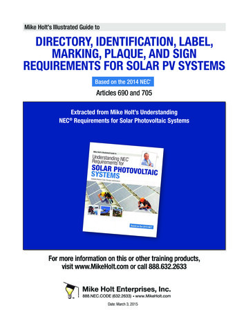
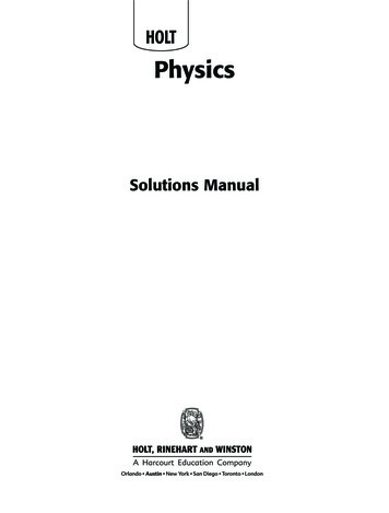
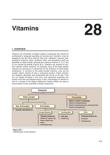
ARTICLE220BRANCH-CIRCUIT, FEEDER,AND SERVICE CALCULATIONSIntroduction to Article 220—Branch-Circuit, Feeder, and Service CalculationsThis five-part article focuses on the requirements for calculating the minimum size of branch circuit, feeder, and serviceconductors.Part I describes the layout of Article 220 and provides a table of where other types of load calculations can be found in theNEC. Part II provides requirements for branch-circuit calculations and for specific types of branch circuits. Part III covers therequirements for feeder and service calculations, using what’s commonly called the “standard method of calculation.” PartIV provides optional calculations that can be used in place of the standard calculations provided in Parts II and III—if yourinstallation meets certain requirements. Farm Load Calculations are discussed in Part V of the article.In many cases, either the standard method (Part III) or the optional method (Part IV) can be used; however, these two methods don’t yield identical results. In fact, sometimes these two answers may be diverse enough to call for different servicesizes. There’s nothing to say that either answer is right or wrong. If taking an exam, read the instructions carefully to be surewhich method the test wants you to use. As you work through Article 220, be sure to study the illustrations to help you fullyunderstand it. Also be sure to review the examples in Annex D of the NEC to provide more practice with these calculations.220.87 Determining Existing LoadsThe calculation of a feeder or service load for existing installations canbe based on 125 percent of the maximum demand data for one year.Ex: If the maximum demand data for one year isn’t available, the maximum power demand over a 15-minute period continuously recordedover a minimum 30-day period using a recording ammeter or powermeter connected to the highest loaded phase, based on the initial loading at the start of the recording is permitted. The recording must betaken when the building or space is occupied based on the larger ofthe heating or cooling equipment load. Figure 220–36Figure 220–36FREE PDF—Generators & Standby Systems 2014 NEC3www.MikeHolt.com 888.NEC.CODE (632.2633)
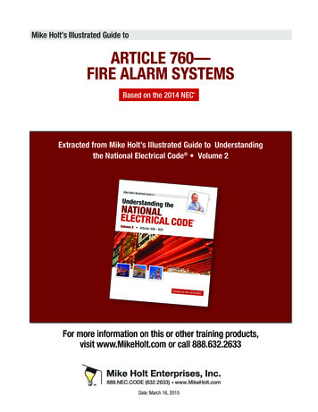
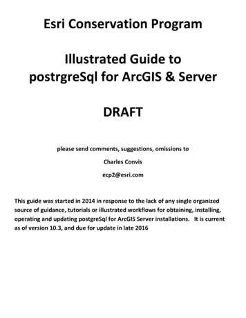
ARTICLE445GENERATORSIntroduction to Article 445—GeneratorsThis article contains the electrical installation, and other requirements, for generators. These requirements include suchthings as where generators can be installed, nameplate markings, conductor ampacity, and disconnecting means.Generators are basically motors that operate in reverse—they produce electricity when rotated, instead of rotating whensupplied with electricity. Article 430, which covers motors, is the longest article in the NEC. Article 445, which covers generators, is one of the shortest. At first, this might not seem to make sense. But you don’t need to size and protect conductors toa generator. You do need to size and protect them to a motor.Generators need overload protection, and it’s necessary to size the conductors that come from the generator. But these considerations are much more straightforward than the equivalent considerations for motors. Before you study Article 445, takea moment to read the definition of “Separately Derived System” in Article 100.445.1 Scope445.11 MarkingArticle 445 contains the installation and other requirements forgenerators.Each generator must be provided with a nameplate indicating themanufacturer’s name, rated frequency, number of phases, rating inkilowatts or kilovolt amperes, volts and amperes corresponding to therating, RPM, insulation class and rated ambient temperature or ratedtemperature rise, and time rating.Author’s Comment:nGenerators, associated wiring, and equipment must beinstalled in accordance with the following requirementsdepending on their use: Nameplates for portable generators rated more than 15 kW and for allstationary generators must also give the power factor, the subtransientand transient impedances, insulation system class, and time rating.Article 695, Fire PumpsArticle 700, Emergency SystemsArticle 701, Legally Required Standby SystemsArticle 702, Optional Standby SystemsFREE PDF—Generators & Standby Systems 2014 NECAll generators must be marked by the manufacturer indicating whetheror not the generator neutral is bonded to the generator frame. Wherethe bonding of a generator is modified in the field, additional markingmust be provided to indicate whether or not the generator neutral isbonded to the generator frame. Figure 445–14www.MikeHolt.com 888.NEC.CODE (632.2633)
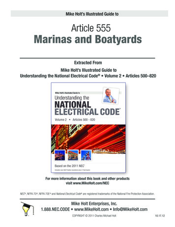
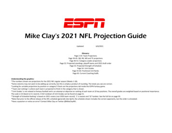
Article 445 GeneratorsFigure 445–1Figure 445–2445.12 Overcurrent ProtectionExample: What size conductor is required from a 100A overcurrent protection device on 20 kW 120/240V single-phasegenerator to a 200A service rated transfer switch? Figure 445–3(A) Generators. Generators must be protected from overload by inherent design, circuit breakers, fuses, or other identified overcurrentprotective means.(a) 4 AWG(b) 3 AWG(c) 2 AWG(d) 1 AWGAnswer: (b) 3 AWG, Table 310.15(B)(16), rated 100A at 75 C[110.14(C)(1)(b)].445.13 Ampacity of ConductorsScan this QR code for a video of this Code rule. See page xixfor information on how to use the QR codes.The ampacity of the conductors from the generator windingto the line-side of the generator overcurrent protection device must notbe less than 115 percent of the nameplate current rating of the generator. Figure 445–2Author’s Comment:nSince the overcurrent protection device is typically part of thegenerator, this rule applies to the generator manufacturer, notthe installer.nConductors from the load-side of the generator overcurrentprotection device to the transfer switch are sized in accordance with 240.4.FREE PDF—Generators & Standby Systems 2014 NECFigure 445–35www.MikeHolt.com 888.NEC.CODE (632.2633)
Article 445 GeneratorsGenerators that aren’t a separately derived system must have the neutral conductor sized to carry the maximum unbalanced current asdetermined by 220.61 and serve as part of the effective ground-faultcurrent path and be not smaller than required by 250.30. Figure 445–4445.20 Ground-Fault Circuit InterrupterProtection for Receptacles on 15 kWor Smaller Portable GeneratorsPortable generators rated 15 kW or smaller manufactured or remanufactured after January 1, 2015 containing a 125/250V lockingreceptacle must have 15A, 20A, and 30A, 125V receptacles GFCI protected, or have a feature that will disable the 125V receptacle whenthe 125/250V locking receptacle is in use. Figure 445–5Figure 445–4445.18 Disconnecting MeansGenerators must have one or more lockable disconnecting means thatdisconnects all power, except where:Figure 445–5(1) The generator is portable with a cord-and-plug connection, or(2) Where both of the following apply:Author’s Comment:(a) The driving means for the generator can be readily shut down, rendered unable to start, and is lockable in accordance with 110.25,andnThis rule was revised via a Tentative Interim Amendment14-2 effective November 11, 2013.(b) The generator isn’t arranged to operate in parallel with anothergenerator or other source of voltage.CAUTION: If one generator is used to supply emergency, legally required, as well as optional standbypower, then there must be at least two transfer switches; onefor emergency power, another for legally required, and one foroptional stand-by power [700.5(D)].FREE PDF—Generators & Standby Systems 2014 NEC6www.MikeHolt.com 888.NEC.CODE (632.2633)
ARTICLE700EMERGENCY SYSTEMSIntroduction to Article 700—Emergency SystemsEmergency systems are legally required, often as a condition of an operating permit for a given facility. The authority havingjurisdiction makes the determination as to whether such a system is necessary for a given facility and what it must entail.Sometimes, it simply provides power for exit lighting and exit signs upon loss of the main power or in the case of fire.Its purpose isn’t to provide power for normal business operations, but rather to provide lighting and controls essential forhuman life safety.The general goal is to keep the emergency operation as reliable as possible. The emergency system must be able to supplyall emergency loads simultaneously. When the emergency supply also supplies power for other non emergency loads, theemergency loads take priority over the others, and those other loads must be subject to automatic load pickup and loadshedding to support the emergency loads if the emergency system doesn’t have adequate capacity and rating for all loadssimultaneously.As you study Article 700, keep in mind that emergency systems are essentially lifelines for people. The entire article is basedon keeping those lifelines from breaking.Part I. General700.1 ScopeArticle 700 applies to the installation, operation, and maintenance ofemergency power systems. These consist of circuits and equipmentintended to supply illumination or power within 10 seconds [700.12]when the normal electrical supply is interrupted. Figure 700–1Note 3: For specific locations where emergency lighting is required, seeNFPA 101, Life Safety Code.Figure 700–1FREE PDF—Generators & Standby Systems 2014 NEC7www.MikeHolt.com 888.NEC.CODE (632.2633)
Article 700 Emergency SystemsAuthor’s Comment:n700.3 Tests and MaintenanceEmergency power systems are generally installed where artificial illumination is required for safe exiting and for paniccontrol in buildings subject to occupancy by large numbers ofpersons, such as hotels, theaters, sports arenas, health carefacilities, and similar institutions.Author’s Comment:nEmergency power system testing consists of acceptancetesting and operational testing.(A) Conduct or Witness Test. To ensure that the emergency powersystem meets or exceeds the original installation specifications, theauthority having jurisdiction must conduct or witness an acceptancetest of the emergency power system upon completion.700.2 Definitions(B) Periodic Testing. Emergency power systems must be periodicallytested to ensure that adequate maintenance has been performed andthat the systems are in proper operating condition.Emergency Systems. Emergency power systems are those systems legally required
NEC REQUIREMENTS FOR GENERATORS AND STANDBY POWER SYSTEMS. Based on the 2014 NEC Mike Holt’s Illustrated Guide to. For more information on this or other training products, visit www.MikeHolt.com or call 888.632.2633 Rule 220.87, Articles 445, 700, 701, and 702