Transcription
Mike Holt’s Illustrated Guide toTHE TOP 10 RULES OF THE2014 NATIONAL ELECTRICAL CODE Based on the 2014 NEC Rules 110.14, 110.16, 210.8, 210.12, 240.21, 250.24, 250.122, 404.2, 406.12, 680.26Extracted from Mike Holt’s Illustrated Guide to Understandingthe National Electrical Code Volumes 1 and 2For more information on this or other training products,visit www.MikeHolt.com or call 888.632.2633Date: June 21, 2016
NOTICE TO THE READERThe publisher does not warrant or guarantee any of theproducts described herein or perform any independentanalysis in connection with any of the product informationcontained herein. The publisher does not assume, andexpressly disclaims, any obligation to obtain and includeinformation other than that provided to it by the manufacturer.The reader is expressly warned to consider and adopt allsafety precautions that might be indicated by the activitiesherein and to avoid all potential hazards. By following theinstructions contained herein, the reader willingly assumesall risks in connection with such instructions.The publisher makes no representation or warranties ofany kind, including but not limited to, the warranties of fitness for particular purpose or merchantability, nor are anysuch representations implied with respect to the materialset forth herein, and the publisher takes no responsibilitywith respect to such material. The publisher shall not beliable for any special, consequential, or exemplary damages resulting, in whole or part, from the reader’s use of,or reliance upon, this material.Author: Mike HoltTechnical Illustrator: Mike CulbreathCOPYRIGHT 2015 Charles Michael HoltProduced and Printed in the USAAll rights reserved. No part of this work covered by thecopyright hereon may be reproduced or used in any form orby any means graphic, electronic, or mechanical, includingphotocopying, recording, taping, or information storageand retrieval systems without the written permission ofthe publisher. You can request permission to use materialfrom this text by either calling 888.632.2633, e-mailingInfo@MikeHolt.com, or visiting www.MikeHolt.com.ABOUT THE AUTHORMike Holt worked his way up throughthe electrical trade. He began as anapprentice electrician and becameone of the most recognizedexperts in the world as it relatesto electrical power installations.He’s worked as a journeymanelectrician, master electrician, and electrical contractor.Mike’s experience in the realworld gives him a uniqueunderstanding of how the NECrelates to electrical installations from a practical standpoint.You’ll find his writing style to be direct, nontechnical,and powerful.Did you know Mike didn’t finish high school? Soif you struggled in high school or didn’t finish at all,don’t let it get you down. However, realizing that success depends on one’s continuing pursuit of education,Mike immediately attained his GED, and ultimatelyattended the University of Miami’s Graduate School fora Master’s degree in Business Administration.Mike resides in Central Florida, is the father of sevenchildren, has five grandchildren, and enjoys many outside interests and activities. He’s a nine-time NationalBarefoot Water-Ski Champion (1988, 1999, 2005–2009, 2012–2013). He’s set many national recordsand continues to train year-round at a World competition level (www.barefootwaterskier.com).What sets him apart from some is his commitmentto living a balanced lifestyle; placing God first, family,career, then self.For more information, call 888.NEC.CODE (632.2633), ore-mail Info@MikeHolt.com.NEC , NFPA 70 , NFPA 70E and National ElectricalCode are registered trademarks of the National FireProtection Association.This logo is a registered trademark of MikeHolt Enterprises, Inc.I dedicate this book to theLord Jesus Christ,my mentor and teacher.Proverbs 16:3
TABLE OF CONTENTSArticle 110—Requirements forElectrical InstallationsRule 1Rule 2Article 404—SwitchesRule 8404.2 Switch Connections. 36110.14 Conductor Termination and Splicing. 4110.16 Arc-Flash Hazard Warning. 9Article 406—Receptacles, Cord Connectors,and Attachment Plugs (Caps)Article 210—Branch CircuitsRule 3Rule 4Rule 9406.12 Tamper-Resistant Receptacles. 39210.8 GFCI Protection. 11210.12 Arc-Fault Circuit-Interrupter Protection. 18Article 680—Swimming Pools, Spas, HotTubs, Fountains, and Similar InstallationsArticle 240—Overcurrent ProtectionRule 5Rule 10680.26 Equipotential Bonding. 41240.21 Overcurrent Protection Location inCircuit. 22Article 250—Grounding and BondingRule 6250.24 Service Equipment-Grounding andBonding. 27Rule 7250.122 Sizing Equipment GroundingConductor. 33FREE PDF—Top 10 Safety Rules of the 2014 NEC3www.MikeHolt.com 888.NEC.CODE (632.2633)
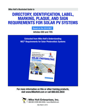
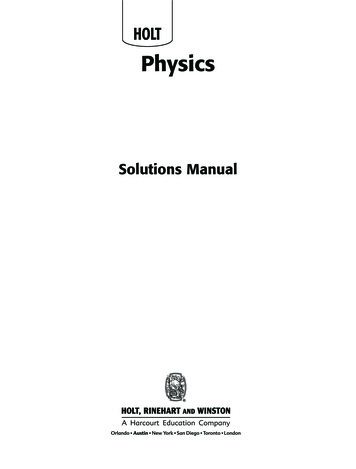
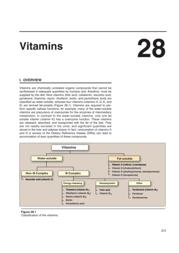
ARTICLE110REQUIREMENTS FORELECTRICAL INSTALLATIONSIntroduction to Article 110—Requirements for Electrical InstallationsArticle 110 sets the stage for how you’ll implement the rest of the NEC. This article contains a few of the most important andyet neglected parts of the Code. For example:–––––How should conductors be terminated?What kinds of warnings, markings, and identification does a given installation require?What’s the right working clearance for a given installation?What do the temperature limitations at terminals mean?What are the NEC requirements for dealing with flash protection?It’s critical that you master Article 110, and that’s exactly what this Illustrated Guide to Understanding the National ElectricalCode is designed for. As you read this article, you’re building your foundation for correctly applying the NEC. In fact, this article itself is a foundation for much of the Code. The purpose for the National Electrical Code is to provide a safe installation,but Article 110 is perhaps focused a little more on providing an installation that’s safe for the installer and maintenance electrician, so time spent in this article is time well spent.Part I. General RequirementsRule #1:110.14 Conductor Termination and SplicingConductor terminal and splicing devices must be identified for the conductor material and they must be properly installed and used. Figure110–21Author’s Comment:nSwitches and receptacles marked CO/ALR are designed toensure a good connection through the use of a larger contact area and compatible materials. The terminal screwsare plated with the element called “Indium.” Indium is anextremely soft metal that forms a gas-sealed connection withthe aluminum conductor.FREE PDF—Top 10 Safety Rules of the 2014 NECFigure 110–214www.MikeHolt.com 888.NEC.CODE (632.2633)
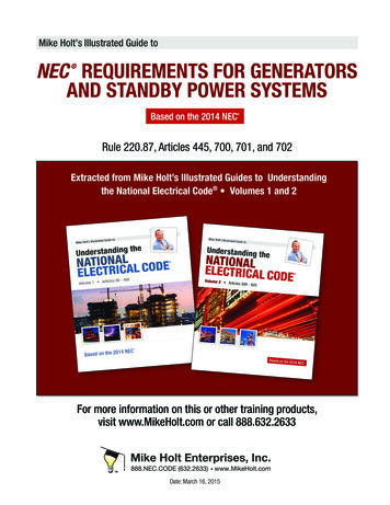
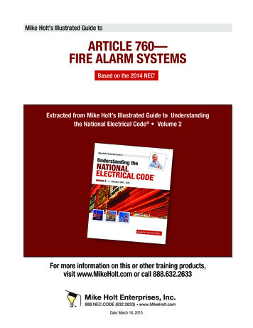
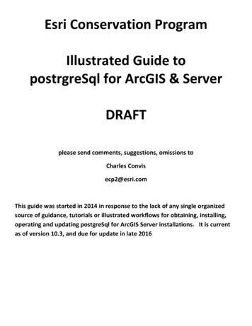
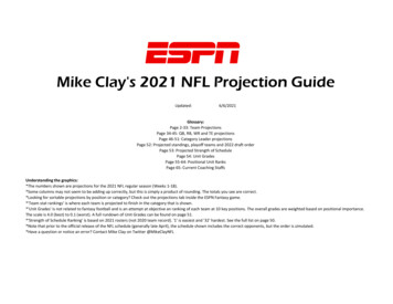
Article 110 Requirements for Electrical InstallationsAuthor’s Comment:Connectors and terminals for conductors more finely stranded thanClass B and Class C, as shown in Table 10 of Chapter 9, must be identified for the use of finely stranded conductors. Figure 110–22nFew terminations are listed for the mixing of aluminum andcopper conductors, but if they are, that’ll be marked on theproduct package or terminal device. The reason copper andaluminum shouldn’t be in contact with each other is becausecorrosion develops between the two different metals due togalvanic action, resulting in increased contact resistance atthe splicing device. This increased resistance can cause thesplice to overheat and cause a fire.Note: Many terminations and equipment are either marked with atightening torque or have the torque values included in the product’sinstructions. Figure 110–23Figure 110–22Author’s Comment:nAccording to UL Standard 486 A-B, a terminal/lug/connector must be listed and marked for use with other than ClassB stranded conductors. With no marking or factory literature/instructions to the contrary, terminals may only be used withClass B stranded conductors.nSee the definition of “Identified” in Article 100.nConductor terminations must comply with the manufacturer’s instructions as required by 110.3(B). For example, if theinstructions for the device state “Suitable for 18-12 AWGStranded,” then only stranded conductors can be used withthe terminating device. If the instructions state “Suitable for18-12 AWG Solid,” then only solid conductors are permitted,and if the instructions state “Suitable for 18-12 AWG,” theneither solid or stranded conductors can be used with the terminating device.Figure 110–23Author’s Comment:nCopper and Aluminum Mixed. Copper and aluminum conductors mustnot make contact with each other in a device unless the device islisted and identified for this purpose.FREE PDF—Top 10 Safety Rules of the 2014 NEC5Conductors must terminate in devices that have been properly tightened in accordance with the manufacturer’s torquespecifications included with equipment instructions. Failureto torque terminals can result in excessive heating of terminals or splicing devices due to a loose connection. A looseconnection can also lead to arcing which increases the heating effect and may also lead to a short circuit or ground fault.Any of these can result in a fire or other failure, includingan arc-flash event. In addition, this is a violation of 110.3(B),which requires all equipment to be installed in accordancewith listing or labeling instructions.www.MikeHolt.com 888.NEC.CODE (632.2633)
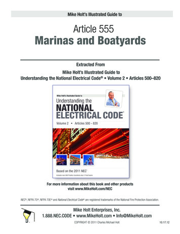
Article 110 Requirements for Electrical InstallationsQuestion: What do you do if the torque value isn’t provided withthe device?Question: What if the conductor is larger than the terminaldevice?Answer: In the absence of connector or equipment manufacturer’s recommended torque values, Table I.1, Table I.2, and TableI.3 contained in Annex I may be used to correctly tighten screwtype connections for power and lighting circuits.Answer: This condition needs to be anticipated in advance, andthe equipment should be ordered with terminals that’ll accommodate the larger conductor. However, if you’re in the field, youshould: Contact the manufacturer and have them express deliver youthe proper terminals, bolts, washers, and nuts, or Order a terminal device that crimps on the end of the largerconductor and reduces the termination size.Author’s Comment:nTerminating conductors without a torque tool can result in animproper and unsafe installation. If a torque screwdriver isn’tused, there’s a good chance the conductors aren’t properlyterminated.Terminals for more than one conductor and terminals used for aluminum conductors must be identified for this purpose, either within theequipment instructions or on the terminal itself. Figure 110–25(A) Terminations. Conductor terminals must ensure a good connection without damaging the conductors and must be made by pressureconnectors (including set screw type) or splices to flexible leads. Figure110–24Figure 110–25Author’s Comment:Figure 110–24nAuthor’s Comment:nSplit-bolt connectors are commonly listed for only two conductors, although some are listed for three conductors.However, it’s a common industry practice to terminate asmany conductors as possible within a split-bolt connector,even though this violates the NEC. Figure 110–26See the definition of “Connector, Pressure” in Article 100.(B) Conductor Splices. Conductors must be spliced by a splicingdevice identified for the purpose or by exothermic welding.FREE PDF—Top 10 Safety Rules of the 2014 NEC6www.MikeHolt.com 888.NEC.CODE (632.2633)
Article 110 Requirements for Electrical InstallationsFigure 110–26Figure 110–28Author’s Comment:nAuthor’s Comment:Conductors aren’t required to be twisted together prior to theinstallation of a twist-on wire connector, unless specificallyrequired in the installation instructions. Figure 110–27nSee the definition of “Energized” in Article 100.Underground Splices:Single Conductors. Single direct burial conductors of types UF or USEcan be spliced underground without a junction box, but the conductors must be spliced with a device listed for direct burial [300.5(E) and300.15(G)]. Figure 110–29Figure 110–27Unused circuit conductors aren’t required to be removed. However, toprevent an electrical hazard, the free ends of the conductors must beinsulated to prevent the exposed end of the conductor from touchingenergized parts. This requirement can be met by the use of an insulated twist-on or push-on wire connector. Figure 110–28FREE PDF—Top 10 Safety Rules of the 2014 NECFigure 110–297www.MikeHolt.com 888.NEC.CODE (632.2633)
Article 110 Requirements for Electrical InstallationsMulticonductor Cable. Multiconductor UF or USE cable can have theindividual conductors spliced underground without a junction box aslong as a listed splice kit that encapsulates the conductors as well asthe cable jacket is used.(C) Temperature Limitations (Conductor Size). Conductors are tobe sized using their ampacity from the insulation temperature ratingcolumn of Table 310.15(B)(16) that corresponds to the lowest temperature rating of any terminal, device, or conductor of the circuit.Author’s Comment:nConductors with insulation temperature ratings higher thanthe termination’s temperature rating can be used for ampacity adjustment, correction, or both. Figure 110–30Figure 110–31Figure 110–30Figure 110–32(1) Equipment Temperature Rating Provisions. Unless the equipment is listed and marked otherwise, conductor sizing for equipmentterminations must be based on Table 310.15(B)(16) in accordance with(a) or (b):(4) Motors marked with design letters B, C, or D, conductors havingan insulation rating of 75 C or higher can be used, provided theampacity of such conductors doesn’t exceed the 75 C ampacity.Figure 110–33(a) Equipment Rated 100A or Less.(b) Equipment Rated Over 100A.(1) Conductors must be sized using the 60 C temperature column ofT
FREE PDF—Top 10 Safety Rules of the 2014 NEC 3www.MikeHolt.com 888.NEC.CODE (632.2633) Article 110—Requirements for Electrical Installations Rule 1 110.14 Conductor Termination and Splicing . 4 Rule 2 110.16 Arc-Flash Hazard Warning . 9 Article 210—Branch Circuits