Transcription
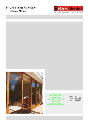
2016 Pella CorporationPart Number: 81520102INSTALLATION INSTRUCTIONSIMPERVIA SLIDING PATIO DOOR HORIZONTALAND VERTICAL MULLION ASSEMBLYYOU WILL NEED TO SUPPLY: Pella Window and Door Installation Sealant or equivalenthigh quality, multi-purpose sealant (2 to 3 tubes per door)TOOLS REQUIRED: Sealant gun #2 Phillips ScrewdriversSEALANTSEALANTFOR MULLION APPLICATIONS: I bar joining connector Pella silicone foam tape Mullion end plug (2) Field applied fins (4 pcs. per unit) Head drip fin (Vertical Mullion applications only) Optional jamb extension (horizontal mullion only) Optional interior Mull Cover (horizontal mull only) Rubber malletInstallation will require two or more persons for safety reasons.REMEMBER TO USE APPROPRIATE PERSONAL PROTECTIVE EQUIPMENT1MULLION ASSEMBLY:HORIZONTAL MULLION ASSEMBLY:A. Apply two strips of foam tape acrossthe bottom of the transom frame.Note: The tape must extend the fullwidth of the transom frame.Optional JambExtensionAB. Place a foam plug at each end of thetop between the exterior rib and thejoining mullion groove.CC. Position and align the transom with thesliding door.D. Start the I bar joining connector fromone end and drive it to the full width ofthe units.OptionalMull CoverTransom UnitSliding DoorBDNote: A rubber mallet may be used todrive the I bar joining connector intoposition. If necessary, the I bar joiningconnector can be cut in half and drivenfrom each end.E. (Block Install Only): Apply sealant to the ends of the mullion joint. The bead of sealantshould extend from the center of the mullion joint to the exterior of the unit, coveringthe foam plug.Always read the Pella Impervia Limited Warranty before purchasing or installingPella Impervia products. By installing this product, you are acknowledging that this LimitedWarranty is part of the terms of the sale. Failure to comply with all Pella Impervia installation andmaintenance instructions may void your Pella Impervia product warranty. See Limited Warrantyfor complete details on http://warranty.pellaimpervia.com.Page 1 of 5
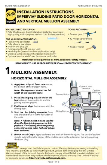
1MULLION ASSEMBLY (CONTINUED):VERTICAL MULLION ASSEMBLY:A. Lay the units on a smooth clean surface,exterior side up to perform these steps.B. Apply two strips of foam tape down thefixed door frame sides. Place one strip on theinterior rib and one strip on the exterior rib.C. Position and align the sliding door with thefixed door.D. Place a foam plug at the top and bottombetween the exterior rib and the joiningmullion groove.E. Start the I bar joining connector from oneend and drive it to the full height of the doors.Note: A rubber mallet may be used to drivethe I bar joining connector into position.F. Apply a bead of sealant, covering themullion joint from the center of the I barjoining connector to the exterior. For BlockInstall - apply sealant at the head G. Apply a reinforcement plate at the headusing the square notches to align the plate tothe head frame screws in the 1-1/2" wide flatgroove to the interior side of the frame.RIBHHGH. Secure the plate with #8 x 1" pan head sheetmetal screws, using three screws per doorhead.I. Align the reinforcement plate at the sillusing the center 3/8"W diameter holes toalign the plate to the sill frame screws in the1-1/2" wide flat groove.J. Secure the plate with #8 x 1" pan head sheetmetal screws, using three screws per door sill.Block install; Assembly is complete.Fin Install; Proceed to step 2.Page 2 of 5JJI
2 APPLYING INSTALLATION FINS:A. Cut the fins to length. Using the followingformula, cut the fins to length, making surethe end cut is square on both ends.Cut to length usinggiven formulaAAHeads: Length Combination width 2-1/2"Jambs: Length Combination height 1-1/4"BB. Notch the ends of the fins. Measure andmark 1-7/16" from each end of the fins. Usinga hacksaw, cut the fin receptor leg at the mark.Finish removing the bottom receptor legs byscoring the fin with a utility knife and snapping it1-7/16"off the fin.Note: When using fins on all four sides, all endsmust be notched. If no fin is used at the sill, DONOT notch the bottom of the jamb fins.Frame receptor leg1-7/16"FrameC. Install the two side fins into the top of the framejamb grooves located on the side frame membersof the door. Slide the fins into place.headgrooDDveNote: Spray a solution of water and soap on theframe jamb grooves to reduce sliding friction.CCD. Install and slide the top fin into the framehead groove located in the top frame member.CCNote: The top fin must overlap the exteriorof the side amegrooveSIDE VIEW(Regular Fin)SIDE VIEW(Offset Fin)Page 3 of 5Framejambgroove
INSTALLATION FINS(CONTINUED):2 APPLYINGE. (For Fin Units only) Apply sealant at the mullion ends from the exterior face of the unitback to the fin and 2" both directions along the fin on the interior and exterior side of thefin, as shown in the Horizontal Mullion step 1E.2E2"2"F. (For Fin Units only) Apply tape over the sealant, set back 1/4" from the exterior face.2F1/4"G. Apply sealant at the top of the exterior mullion cover to seal the space between themullion cover and window frame heads. Also apply sealant at each end of the top of thecombination and across the top of the entire combination at the joint where the fin andframe connect to prep for installation of the head drip fin. Install the drip fin immediatelyafter applying sealant to the head either in the shop or at the job site when installing thecombination unit in the opening. Apply a piece of flashing tape at each end overlappingthe head drip fin and nailing fin to hold the fin in place while the sealant sets up.2GSealant at mullion joint and across the top of the combinationSealant in corner across the top of the combination2G2G2GHead2"Sealant at each end and across the top of the combination.Page 4 of 52"
HEAD DRIP FIN - REQUIREDFOR VERTICAL MULLION APPLICATIONS:3 APPLYINGA. Apply a bead of sealant along the wholewidth of the mulled composite behind theexterior rib.B. On vertical mulls, cut the head drip to thewidth of the units. Attach the head drip tothe top of units aligning the ends and seal tothe frame on both ends.Note: The head drip may either be rivetedto the fin or installed when the unit isinstalled. If the head drip is being installedwith the unit, perform Step A at this time.C. Apply a piece of flashing tape at each endoverlapping the head drip fin and nailing fin tohold the fin in place while the sealant sets up.Page 5 of 53AA3BBINTERIOREXTERIOR3C
Always read the Pella Impervia Limited Warranty before purchasing or installing Pella Impervia products. By installing this product, you are acknowledging that this Limited Warranty is part of the terms of the sale. Failure to comply with all Pella Impervia installation and maintenance instructions may void your Pella Impervia product warranty.