Transcription
October 2010Distributor/Dealer Service Instructions for:Safety Recall K14Power Sliding Door WiringModels2008-2009 (RT) Dodge Grand Caravan and Chrysler Town & CountryNOTE: This repair procedure applies only to the above vehicles equipped withpower sliding doors (sales codes JRA and JRB).IMPORTANT: Some of the involved vehicles may be in Distributor/Dealerused vehicle inventory. Distributor/Dealer should complete this recall serviceon these vehicles before retail delivery. Distributor/Dealers should also performthis recall on vehicles in for service. Involved vehicles can be determined by usingthe VIP inquiry process.SubjectThe right and/or left power sliding door wiring harnesses on about 15,180 of theabove vehicles may chafe on the sliding door hinge when operating the slidingdoor. This could cause the sliding door latch to overheat and cause a fire inside thesliding door.RepairThe power sliding door wiring harness and the drive motor wiring harness must beinspected for damage and repaired/replaced as necessary. The two harnesses mustthen be tie strapped together and routed under the sliding door weather strip and atab/wedge installed on each sliding door lower hinge bracket.Copyright 2010, Chrysler Group LLC, All Rights Reserved
Safety Recall K14 – Power Sliding Door WiringPage 2Parts InformationPart NumberDescriptionCATFK143AATab/Wedge PackageEach package contains the following components:QuantityDescription2Tab/WedgeEach dealer to whom vehicles in the recall were assigned will receive enoughTab/Wedge packages to service about 20% of those vehicles.Part NumberDescriptionCATFK142AAHarness, Power Sliding Door (right)Part NumberDescriptionCATFK141AAHarness, Power Sliding Door (left)Part NumberDescriptionCLG0J061AAPlastic Tie Strap PackageQuantity2DescriptionStrap, Plastic TiePart NumberDescription05018528AAWire Splice Band Package (for 12 gauge wire)05018526AAWire Splice Band Package (for 16 gauge wire)05018395AAWire Splice Band Package (for 20 gauge wire)Each package contains the following components:QuantityDescription1Band, Brass Splice1Tube, Heat Shrink
Safety Recall K14 – Power Sliding Door WiringPage 3Special ToolsThe following special tool may be required to perform this repair: 10042Wire Splice Crimp ToolNOTE: One wire splice crimp tool was mailed to each dealer free ofcharge in June, 2007. For warranty issues regarding the wire splicecrimping tool sent in June, contact Wright Tool Company at1-800-783-9826.Additional wire splice crimp tools can be purchased, at dealer expense, bycalling Miller Special Tools at 1-800-801-5420 during regular businesshours. Contact Miller Special Tools regarding warranty issues on anypurchased tools.
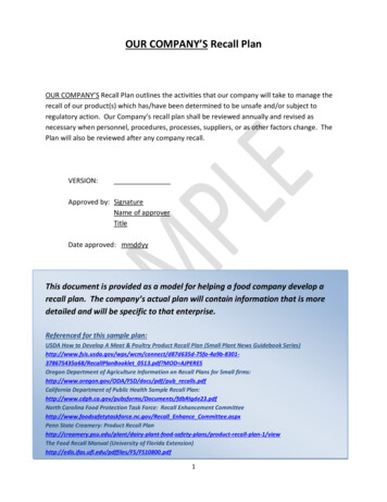
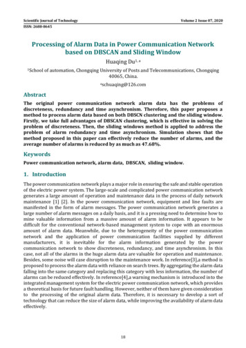
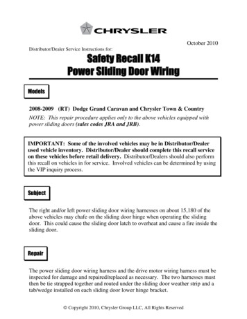
Safety Recall K14 – Power Sliding Door WiringPage 4Service ProcedureA. Inspect Chain Link Track and Wiring Harnesses1. Open the driver’s side power sliding door.2. Partially remove the sliding door weather seal (Figure 1).3. Inspect the drive motor wiring harness and power sliding door wiring harness fora wire chafe condition (Figure 1). Then inspect the chain link track for brokenlinks, damaged wires, or the chain link track being disconnected from the lowerhinge bracket (Figure 2). If there is no damage to either wiring harness or the chain link track,continue with Section B of this procedure. If no more than two wires are chafed on the power sliding door wiringharness or no more than four wires are damaged on the drive motor wiringharness, continue with Section C of this procedure. If the chain link track is damaged or the chain link is disconnected or morethan two wires on the power sliding door wiring harness are damaged,continue with Step 4 of this procedure.WEATHER SEALPARTIALLY REMOVEDDRIVE MOTORWIRING HARNESSLOWER “B” POSTTRIM PANELINSPECT BOTH WIRINGHARNESSES IN THISLOCATION FOR CHAFECONDITIONCHAFEDCONDITIONPOWER SLIDING DOORWIRING HARNESSFigure 1 – Inspect Wiring Harnesses (Driver’s Side Shown)
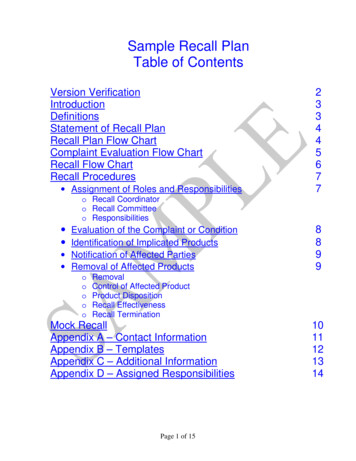
Safety Recall K14 – Power Sliding Door WiringPage 5Service Procedure (Continued)REPLACE POWER SLIDING DOORWIRING HARNESS IF THE CHAINLINK TRACK HAS BROKEN LINKSOR IF THE WIRING HARNESS ISDAMAGE IN THE CHAIN LINK AREAREPLACE POWER SLIDING DOORWIRING HARNESS IF THE CHAINLINK TRACK IS DISCONNECTEDFROM THE LOWER HINGEBRACKETLOWER HINGEBRACKETFigure 2 – Inspect Chain Link Track For Damage4. Place both front seats to the full forward travel position. This seat position willallow access to all trim panels during the repair procedure.5. Open the hood and disconnect the negative battery cable.
Safety Recall K14 – Power Sliding Door WiringPage 6Service Procedure (Continued)FRONT DOOR SILL PLATESLIDING DOOR SILL PLATEFigure 3 – Sill Plate Removal6. Carefully unsnap the front door sill plate and sliding door sill plate by lifting theinside edge of the sill plates (Figure 3).NOTE: Remove the cap plug and nut at the rear of the front driver side sillplate, before attempting to remove the sill plate (Figure 13).7. Carefully unsnap the lower “B” post trim panel (Figure 1).8. Disconnect the power sliding door switch, located on the lower “B” post trimpanel, from the body wiring harness connector.
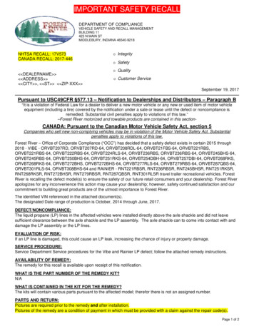
Safety Recall K14 – Power Sliding Door WiringPage 7Service Procedure (Continued)SLIDING DOORWIRING HARNESSCONNECTORPOWER SLIDINGDOOR WIRINGHARNESSCONNECTORWIRING HARNESSRETAINERLOCATIONSLOWER SLIDINGDOOR HINGEBRACKETSLIDINGDOORGRAY LOCKINGTABFigure 4 – Power Sliding Door Wiring Harness Removal (Driver’s Side Shown)9. Disconnect the 10 way power sliding door wiring harness connector from thesliding door wiring harness connector by first pushing the gray locking tabupward (downward on the passenger side). Then push down on the release tabwhile separating the connector (Figure 4).10. Remove the power sliding door wiring harness from the sliding door and lowerhinge bracket by carefully pulling the wiring harness retainers out of theretention holes (Figure 4).
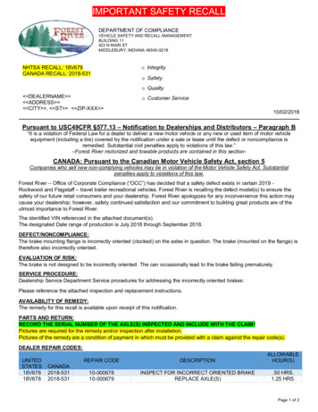
Safety Recall K14 – Power Sliding Door WiringPage 8Service Procedure (Continued)CHAIN LINKTRACKSLIDING DOORLOWER HINGEBRACKETLOCKING TABLOWER HINGEPIVOT LOCATIONFigure 5 – Chain Link Track Removal11. Release the chain link track from the lower hinge pivot by pushing the lockingtab forward and then push the chain link downward (Figure 5).12. Move the power sliding door wiring harness and chain link track forward togain access to the side impact sensor.
Safety Recall K14 – Power Sliding Door WiringPage 9Service Procedure (Continued)DOUBLE WIRINGHARNESSRETENTION HOLESLOWER “B” POSTWIRING HARNESSRETENTION HOLESADDITIONAL WIRINGHARNESS RETENTIONHOLE (PASSENGERSIDE)PASSENGER SIDECAPTIONSIDE IMPACTSENSORFigure 6 – Wiring Harness Retention Holes (Driver’s Side Shown)13. Disconnect the side impact sensor connector (Figure 6).NOTE: The passenger side wiring harness has one additional wiringharness retainer at the side impact sensor (Figure 6 caption).14. Disconnect the 10 way power sliding door harness connector from the bodywiring harness connector located at the lower “B” post. Push the red lockingtab in the direction of the power sliding door harness, then push down on therelease tab while separating the connectors.15. Remove the power sliding door harness from the door track by carefully pullingthe harness retainers out of the retention holes (Figure 6).16. Place the new power sliding door harness into position in the door track.17. Insert the double wiring harness retainers into the door track retention holes andthen insert the two lower “B” post wiring harness retainers into the retentionholes (Figure 6).
Safety Recall K14 – Power Sliding Door WiringPage 10Service Procedure (Continued)18. Connect the 10 way power sliding door wiring harness connector to the bodywiring harness connector located at the lower “B” pillar and slide the redlocking tab in the direction of the body wiring harness.19. Connect the side impact sensor connector (Figure 6).NOTE: The passenger side wiring harness at the side impact sensor hasone additional wiring harness retainer (Figure 6 caption).20. Move the chain link track and wiring harness rearward.21. Install the supplied tab/wedge on the lower hinge pivot located on the slidingdoor lower hinge (Figure 5).NOTE: The tab/wedge must have the “L” facing up on the drivers side ofthe vehicle and the “R” facing up on the passenger side of the vehicle(Figure 7).22. While holding the tab/wedge in place, snap the chain link to the lower hingepivot.TAB/WEDGE INSTALLEDLOCATIONTAB/WEDGE “L” FACES UP ONDRIVER’S SIDE OF VEHICLE –“R” FACES UP ON PASSENGERSIDE OF VEHICLEFigure 7 – Tab/Wedge Installation (Left Side Shown)
Safety Recall K14 – Power Sliding Door WiringPage 11Service Procedure (Continued)23. Lock the chain link in place by pushing the locking tab rearward (Figure 5).24. Insert the power sliding door wiring harness retainers into the lower hinge andsliding door retention holes (Figure 4).25. Connect the 10 way power sliding door wiring harness connector to the slidingdoor wiring harness connector and slide the gray locking tab downward(upward on the passenger side of the vehicle) (Figure 4).26. Connect the power sliding door switch, located on the lower “B” post trimpanel, to the body wiring harness connector.27. Carefully snap the lower “B” post trim panel in place (Figure 1).28. Carefully snap the front door sill plate and sliding door sill plate in place(Figure 3).NOTE: Install the nut and cap plug at the rear of the front driver side sill plate.29. Using the supplied plastic tie strap, secure both harnesses together as shown inFigure 8. The power sliding door wiring harness must be routed to the rear (incar position) of the drive motor wiring harness.CAUTION: Do not over tighten the tie strap.POWER SLIDINGDOOR WIRINGHARNESSDRIVE MOTORWIRING HARNESSPLASTIC TIE WRAPFigure 8 – Tie Strap and Wiring Harness Locations
Safety Recall K14 – Power Sliding Door WiringPage 12Service Procedure (Continued)30. Cut off the tail of the tie strap and rotate the tie strap so that the tie strap lock istucked under the wiring harnesses.31. Install the partially removed sliding door weather seal. Be sure to tuck thewiring harness behind the weather seal inner retaining lip.32. Move the sliding door manually and verify that the lower hinge does not contactthe weather seal and/or any portion of the wiring harnesses.33. Repeat Section A on the passenger (right) side sliding door.34. Connect negative battery cable and close hood.
Safety Recall K14 – Power Sliding Door WiringPage 13Service Procedure (Continued)B. Install Tie Wrap and Tab/Wedge1. Using the supplied plastic tie strap, secure both harnesses together as shown inFigure 9. The power sliding door wiring harness must be routed to the rear (incar position) of the drive motor wiring harness.CAUTION: Do not over tighten the tie strap. Over tightening the tie strapmay cut through the convolute or tape.2. Cut off the tail of the tie strap and rotate the tie strap so that the tie strap lock istucked under the wiring harnesses.3. Install the partially removed sliding door weather seal. Be sure to tuck thewiring harness behind the weather seal inner retaining lip.PLASTIC TIESTRAPPOWER SLIDIING DOORWIRING HARNESSTIE STRAP THE HARNESSJUST ABOVE THE SHEETMETAL DIVISIONFigure 9 – Tie Strap and Wiring Harness Location
Safety Recall K14 – Power Sliding Door WiringPage 14Service Procedure (Continued)CHAIN LINKTRACKSLIDING DOORLOWER HINGEBRACKETLOCKING TABLOWER HINGEPIVOT LOCATIONFigure 10 - Chain Link Track Removal4. Move the sliding door manually and verify that the lower hinge does not contactthe weather seal and/or any portion of the wiring harnesses.5. Release the chain link track from the lower hinge pivot by pushing the lockingtab forward and then push the chain link downward (Figure 10).
Safety Recall K14 – Power Sliding Door WiringPage 15Service Procedure (Continued)TAB/WEDGE INSTALLEDLOCATIONTAB/WEDGE “L” FACES UP ONDRIVER’S SIDE OF VEHICLE –“R” FACES UP ON PASSENGERSIDE OF VEHICLEFigure 11 – Tab/Wedge Installation (Left Side Shown)6. Install the supplied tab/wedge on the lower hinge pivot located on the slidingdoor lower hinge (Figure 10).NOTE: The tab/wedge must have the “L” facing up on the drivers side ofthe vehicle and the “R” facing up on the passenger side of the vehicle(Figure 11).7. While holding the tab/wedge in place, snap the chain link to the lower hingepivot.8. Lock the chain link in place by pushing the locking tab rearward (Figure 10).9. Repeat Section A on the passenger (right) side sliding door.10. Connect negative battery cable and close hood.
Safety Recall K14 – Power Sliding Door WiringPage 16Service Procedure (Continued)C. Wiring Harness Repair1. Place both front seats to the full forward travel position. This seat position willallow access to all trim panels during the repair procedure.2. Open the hood and disconnect the negative battery cable.3. Carefully unsnap the front door sill plate and sliding door sill plate by lifting theinside edge of the sill plates (Figure 12).NOTE: Remove the cap plug and nut at the rear of the front driver side sillplate, before attempting to remove the sill plate (Figure 13).FRONT DOOR SILL PLATESLIDING DOOR SILL PLATEFigure 12 – Sill Plate Removal
Safety Recall K14 – Power Sliding Door WiringPage 17Service Procedure (Continued)POWER SLIDINGDOOR SWITCHLOWER “B” POSTTRIM PANELDRIVERS SIDE SILL PLATECAP PLUG AND NUTLOCATION – DRIVERSSIDE ONLYFigure 13 – Lower “B” Post Trim Panel and Power Sliding Door Switch4. Carefully unsnap the lower “B” post trim panel (Figure 13).5. Disconnect the power sliding door switch, located on the lower “B” post trimpanel, from the body wiring harness connector (Figure 13).6. Disconnect the affected chaffed wiring harness connector from the main wiringharness connector at the lower “B” post. If the drive motor wiring harness requires repair, note the method used totape the convolute and then remove the electrical tape from the convolute.Slide the wires through the split in the convolute to expose the chaffedwires. Continue to Step 10 of this procedure. If the power sliding door wiring harness requires repair, continue with Step 7of this procedure.
Safety Recall K14 – Power Sliding Door WiringPage 18Service Procedure (Continued)LOWER “B” POSTWIRING HARNESSRETAINERSBLACK PLASTIC SPLITTUBEREMOVE THIS WIRINGHARNESS RETAINER TOREPAIR HARNESSFigure 14 – Power Sliding Door Wiring Harness Retainers7. Disengage the two lower “B” post wiring harness retainers from the retentionholes (Figure 14).8. Remove the wiring harness retainer from the front of the black plastic split tubeof the power sliding door wiring harness, noting its original location (Figure 14).9. Carefully unwrap the power sliding door wiring harness starting at the front end(in car position) of the black plastic split tube (Figure 14). Unwrap enough ofthe cloth tape to expose the chaffed wires.10. Select the appropriate wire splice band package based on the wire gauge of thechaffed wire. The power sliding door harness has nine 16-gauge wires. Thedrive motor harness has two 20-gauge wires and two 12-gauge wires.
Safety Recall K14 – Power Sliding Door WiringPage 19Service Procedure (Continued)11. Using diagonal cutters, cutthrough the damaged wirein the middle of the chaffedarea (Figure 15).DAMAGED WIRECHAFFED AREA12. Remove approximatelyone-half (½) inch (13 mm)of insulation from bothwires using wire strippers.13. Install a piece of shrinktube over one of the cutwires (Figure 16).DIAGONAL CUTTERSFigure 15 – Cut Damage Wire14. Insert both cut wires intothe splice band and crimpthem together using wiresplice crimp tool 10042(Figure 16).SHRINK TUBEWIRE SPLICE CRIMP TOOL 10042Figure 16 – Crimping Wires Together
Safety Recall K14 – Power Sliding Door WiringPage 20Service Procedure (Continued)15. Using rosin core solder anda soldering gun, solder thewiring connection at thesplice band (Figure 17).SPLICE BANDROSIN CORE SOLDERSHRINK TUBESOLDERING GUNFigure 17 – Soldering the Wiring Connection16. Center the shrink tube overthe soldered wireconnection made in Step15.17. Heat the shrink tube with aheat gun until it shrinksaround the wire and gluecomes out of both ends ofthe shrink tube (Figure 18).18. Repeat Steps 10 – 17 on allchaffed wires.REPAIRED WIRESPLIT TUBEGLUECLOTH TAPEFigure 18 – Shrink Tube
Safety Recall K14 – Power Sliding Door WiringPage 21Service Procedure (Continued)19. When all chaffed wires have been repaired, position the wires in theconvolute/split tube (Figure 18). If the drive motor wiring harness was repaired, tape the drive motor wiringharness with electrical tape as noted in Step 6. Continue with Step 22 of thisprocedure. If the power sliding door wiring harness was repaired, tape the wiringharness using the cloth tape that was previously unwrapped in Step 9(Figure 18). Continue with Step 20 of this procedure.20. Position the wiring harness retainer at the end of the split tube and tape thewiring harness retainer in place with electrical tape (Figure 14).21. Insert the two lower “B” post wiring harness retainers into the retention holes(Figure 14).22. Connect the drive motor wiring harness connector or the power sliding doorwiring harness connector to the body wiring harness connector at the base of the“B” post.23. Connect the power sliding door switch, located on the lower “B” post trimpanel, to the body wiring harness connector (Figure 13).24. Carefully snap the lower “B” post trim panel in place (Figure 13).25. Carefully snap the front door sill plate and sliding door sill plate in place(Figure 12).NOTE: Install the nut and cap plug at the rear of the front driver side sillplate (Figure 13).26. Continue with Section B of this repair procedure.
Safety Recall K14 – Power Sliding Door WiringPage 22Completion Reporting and ReimbursementClaims for vehicles that have been serviced must be submitted on theDealerCONNECT Claim Entry Screen located on the Service tab. Claimssubmitted will be used by Chrysler to record recall service completions andprovide dealer payments.Use the following labor operation numbers and time allowances:Labor OperationTimeNumberAllowanceInspect right and left sliding door wiringharnesses and chain link track, tiestrap/route harnesses under weather stripand install tab/wedge.08-K1-41-820.2 hoursReplace right sliding door wiring harness.08-K1-41-500.4 hoursReplace left sliding door wiring harness.08-K1-41-510.5 hoursRepair right sliding door wiring harnessone or two wires.08-K1-41-520.7 hoursRepair left sliding door wiring harnessone or two wires.08-K1-41-530.7 hoursRepair right drive motor wiring harnessone to four wires.08-K1-41-540.7 hoursRepair left drive motor wiring harnessone to four wires.08-K1-41-550.7 hoursRelated OperationsAdd the cost of the recall parts package plus applicable dealer allowance to yourclaim.NOTE: See the Warranty Administration Manual, Recall Claim ProcessingSection, for complete recall claim processing instructions.Owner Notification and Service SchedulingAll involved vehicle owners should be notified of the service requirement by theirDistributor/Dealers. Owners are requested to schedule appointments for this service.
Safety Recall K14 – Power Sliding Door WiringPage 23Vehicle Lists, Global Recall System, VIP and Distributor/Dealer Follow UpAll involved vehicles have been entered into the Global Recall System (GRS) andVehicle Information Plus (VIP) for distributor/dealer inquiry as needed.GRS provides involved Distributor/Dealers with an updated VIN list of theirincomplete vehicles. Completed vehicles are removed from GRS within several daysof repair claim submission.Distributor/Dealers should perform this repair on all unsold vehicles beforeretail delivery. Distributor/Dealers should also use the VIN list to follow up withall owners to schedule appointments for this repair.Additional InformationIf you have any questions or need assistance in completing this action, pleasecontact your International Service and Parts Manager.Global Service & Parts – InternationalChrysler Group LLC
SAFETY RECALL K14POWER SLIDING DOOR WIRINGDear: (Name)Chrysler has decided that a defect, which relates to motor vehicle safety, exists in some 2008 and 2009model year Dodge Grand Caravan and Chrysler Town & Country vehicles.The problem is.The right and/or left power sliding door wiring harnesses on your vehicle(VIN: xxxxxxxxxxxxxxxxx) may chafe on the sliding door hinge when operatingthe sliding door. This could cause the sliding door latch to overheat and cause afire inside the sliding door.What your dealerwill do.Chrysler will repair your vehicle free of charge (parts and labor). To do this,your distributor/dealer will inspect both sliding door wiring harnesses and repair orreplace the wiring harness(s) as required. The inspection will take about ½ hour tocomplete. If wiring harness replacement is required an addition hour will be requiredHowever, additional time may also be necessary depending on service schedules.What you mustdo to ensure yoursafety.Simply contact your distributor/dealer right away to schedule a serviceappointment.If you needhelp.If you have trouble getting your vehicle serviced, please contact the ChryslerDistributor/Dealer nearest your location. A representative will assist you in gettingyour vehicle serviced. This information can be found in the Customer Assistancesection of your Owner’s Manual.We apologize for any inconvenience, but we are sincerely concerned about your safety. Thank you foryour attention to this important matter.Global Service & Parts - InternationalChrysler Group LLCNotification Code K14
Safety Recall K14 - Power Sliding Door Wiring Page 11 23. Lock the chain link in place by pushing the locking tab rearward (Figure 5). 24. Insert the power sliding door wiring harness retainers into the lower hinge and sliding door retention holes (Figure 4). 25. Connect the 10 way power sliding door wiring harness connector to the sliding