Transcription
6808Addressable Fire Alarm Control PanelInstallation and Operation ManualDocument LS10146-001SK-E Rev: :C10/9/2017 ECN: 17-0555
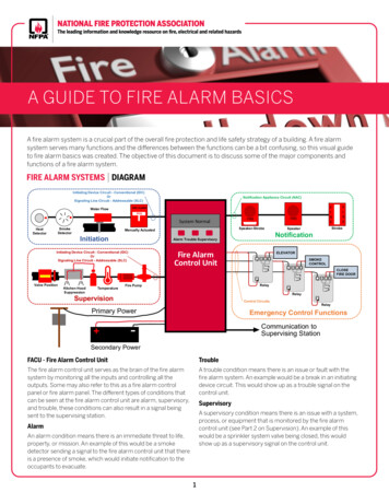
Fire Alarm & Emergency Communication System LimitationsWhile a life safety system may lower insurance rates, it is not a substitute for life and property insurance!An automatic fire alarm system—typically made up of smokedetectors, heat detectors, manual pull stations, audible warningdevices, and a fire alarm control panel (FACP) with remote notification capability—can provide early warning of a developing fire.Such a system, however, does not assure protection against property damage or loss of life resulting from a fire.An emergency communication system—typically made up of anautomatic fire alarm system (as described above) and a life safetycommunication system that may include an autonomous controlunit (ACU), local operating console (LOC), voice communication,and other various inter-operable communication methods—canbroadcast a mass notification message. Such a system, however,does not assure protection against property damage or loss of liferesulting from a fire or life safety event.The Manufacturer recommends that smoke and/or heat detectorsbe located throughout a protected premises following therecommendations of the current edition of the National FireProtection Association Standard 72 (NFPA 72), manufacturer'srecommendations, State and local codes, and therecommendations contained in the Guide for Proper Use of SystemSmoke Detectors, which is made available at no charge to allinstalling dealers. This document can be found at http://www.systemsensor.com/appguides/. A study by the FederalEmergency Management Agency (an agency of the United Statesgovernment) indicated that smoke detectors may not go off in asmany as 35% of all fires. While fire alarm systems are designed toprovide early warning against fire, they do not guarantee warning orprotection against fire. A fire alarm system may not provide timelyor adequate warning, or simply may not function, for a variety ofreasons:Smoke detectors may not sense fire where smoke cannot reachthe detectors such as in chimneys, in or behind walls, on roofs, oron the other side of closed doors. Smoke detectors also may notsense a fire on another level or floor of a building. A second-floordetector, for example, may not sense a first-floor or basement fire.Particles of combustion or “smoke” from a developing fire maynot reach the sensing chambers of smoke detectors because: Barriers such as closed or partially closed doors, walls, chimneys, even wet or humid areas may inhibit particle or smokeflow. Smoke particles may become “cold,” stratify, and not reach theceiling or upper walls where detectors are located. Smoke particles may be blown away from detectors by air outlets, such as air conditioning vents. Smoke particles may be drawn into air returns before reachingthe detector.The amount of “smoke” present may be insufficient to alarm smokedetectors. Smoke detectors are designed to alarm at various levelsof smoke density. If such density levels are not created by a developing fire at the location of detectors, the detectors will not go intoalarm.Smoke detectors, even when working properly, have sensing limitations. Detectors that have photoelectronic sensing chambers tendto detect smoldering fires better than flaming fires, which have littlevisible smoke. Detectors that have ionizing-type sensing chamberstend to detect fast-flaming fires better than smoldering fires.Because fires develop in different ways and are often unpredictablein their growth, neither type of detector is necessarily best and agiven type of detector may not provide adequate warning of a fire.Smoke detectors cannot be expected to provide adequate warningof fires caused by arson, children playing with matches (especiallyin bedrooms), smoking in bed, and violent explosions (caused byescaping gas, improper storage of flammable materials, etc.).2Heat detectors do not sense particles of combustion and alarmonly when heat on their sensors increases at a predetermined rateor reaches a predetermined level. Rate-of-rise heat detectors maybe subject to reduced sensitivity over time. For this reason, therate-of-rise feature of each detector should be tested at least onceper year by a qualified fire protection specialist. Heat detectors aredesigned to protect property, not life.IMPORTANT! Smoke detectors must be installed in the sameroom as the control panel and in rooms used by the system for theconnection of alarm transmission wiring, communications, signaling, and/or power. If detectors are not so located, a developing firemay damage the alarm system, compromising its ability to report afire.Audible warning devices such as bells, horns, strobes, speakers and displays may not alert people if these devices are locatedon the other side of closed or partly open doors or are located onanother floor of a building. Any warning device may fail to alert people with a disability or those who have recently consumed drugs,alcohol, or medication. Please note that: An emergency communication system may take priority over afire alarm system in the event of a life safety emergency. Voice messaging systems must be designed to meet intelligibility requirements as defined by NFPA, local codes, and Authorities Having Jurisdiction (AHJ). Language and instructional requirements must be clearly disseminated on any local displays. Strobes can, under certain circumstances, cause seizures inpeople with conditions such as epilepsy. Studies have shown that certain people, even when they hear afire alarm signal, do not respond to or comprehend the meaningof the signal. Audible devices, such as horns and bells, canhave different tonal patterns and frequencies. It is the propertyowner's responsibility to conduct fire drills and other trainingexercises to make people aware of fire alarm signals andinstruct them on the proper reaction to alarm signals. In rare instances, the sounding of a warning device can causetemporary or permanent hearing loss.A life safety system will not operate without any electrical power. IfAC power fails, the system will operate from standby batteries onlyfor a specified time and only if the batteries have been properlymaintained and replaced regularly.Equipment used in the system may not be technically compatiblewith the control panel. It is essential to use only equipment listed forservice with your control panel.Telephone lines needed to transmit alarm signals from a premisesto a central monitoring station may be out of service or temporarilydisabled. For added protection against telephone line failure,backup radio transmission systems are recommended.The most common cause of life safety system malfunction is inadequate maintenance. To keep the entire life safety system in excellent working order, ongoing maintenance is required per themanufacturer's recommendations, and UL and NFPA standards. Ata minimum, the requirements of NFPA 72 shall be followed. Environments with large amounts of dust, dirt, or high air velocityrequire more frequent maintenance. A maintenance agreementshould be arranged through the local manufacturer's representative. Maintenance should be scheduled monthly or as required byNational and/or local fire codes and should be performed by authorized professional life safety system installers only. Adequate written records of all inspections should be kept.Limit-D-1-20136808 Manual –LS10146-001SK-E:C 10/9/2017
Installation PrecautionsAdherence to the following will aid in problem-free installation with long-term reliability:WARNING - Several different sources of power can beconnected to the fire alarm control panel. Disconnect allsources of power before servicing. Control unit and associatedequipment may be damaged by removing and/or insertingcards, modules, or interconnecting cables while the unit isenergized. Do not attempt to install, service, or operate thisunit until manuals are read and understood.CAUTION - System Re-acceptance Test after SoftwareChanges: To ensure proper system operation, this productmust be tested in accordance with NFPA 72 after any programming operation or change in site-specific software. Reacceptance testing is required after any change, addition ordeletion of system components, or after any modification,repair or adjustment to system hardware or wiring. All components, circuits, system operations, or software functionsknown to be affected by a change must be 100% tested. Inaddition, to ensure that other operations are not inadvertentlyaffected, at least 10% of initiating devices that are not directlyaffected by the change, up to a maximum of 50 devices, mustalso be tested and proper system operation verified.This system meets NFPA requirements for operation at 0-49ºC/32-120º F and at a relative humidity. However, the usefullife of the system's standby batteries and the electronic components may be adversely affected by extreme temperatureranges and humidity. Therefore, it is recommended that thissystem and its peripherals be installed in an environment witha normal room temperature of 15-27º C/60-80º F.Verify that wire sizes are adequate for all initiating and indicating device loops. Most devices cannot tolerate more than a10% I.R. drop from the specified device voltage.Like all solid state electronic devices, this system mayoperate erratically or can be damaged when subjected to lightning induced transients. Although no system is completelyimmune from lightning transients and interference, propergrounding will reduce susceptibility. Overhead or outsideaerial wiring is not recommended, due to an increased susceptibility to nearby lightning strikes. Consult with the Technical Services Department if any problems are anticipated orencountered.Disconnect AC power and batteries prior to removing orinserting circuit boards. Failure to do so can damage circuits.Remove all electronic assemblies prior to any drilling, filing,reaming, or punching of the enclosure. When possible, makeall cable entries from the sides or rear. Before making modifications, verify that they will not interfere with battery, transformer, or printed circuit board location.Do not tighten screw terminals more than 9 in-lbs. Overtightening may damage threads, resulting in reduced terminalcontact pressure and difficulty with screw terminal removal.This system contains static-sensitive components.Always ground yourself with a proper wrist strap before handling any circuits so that static charges are removed from thebody. Use static suppressive packaging to protect electronicassemblies removed from the unit.Follow the instructions in the installation, operating, andprogramming manuals. These instructions must be followed toavoid damage to the control panel and associated equipment.FACP operation and reliability depend upon proper installation.Precau-D1-9-20056808 Manual –LS10146-001SK-E:C 10/9/20173
Documentation FeedbackYour feedback helps us keep our documentation up-to-date and accurate. If you have a question or encounter a problem not coveredin this manual, contact Silent Knight Technical Support at 800-446-6444.Please give the following information: Product name and version number (if applicable)Printed manualTopic TitlePage number (for printed manual)Brief description of content you think should be improved or correctedYour suggestion for how to correct/improve documentationTo order parts, contact Silent Knight Sales at 800-328-0103.eVance , Honeywell , Silent Knight , and SWIFT are registered trademarks of Honeywell International Inc. Microsoft and Windows are registered trademarks ofthe Microsoft Corporation. Chrome and Google are trademarks of Google Inc. Firefox is a registered trademark of The Mozilla Foundation. 2018. All rights reserved. Unauthorized use of this document is strictly prohibited.46808 Manual –LS10146-001SK-E:C 10/9/2017
ContentsSection 1: Introduction . 101.1: Overview of Basic System.101.1.1: Hardware Features .101.1.2: Common Communication / Annunciation Link System Hardware Features .101.1.3: Software Features .101.2: About this Manual.101.2.1: Terms Used in this Manual.101.3: Compatible Products.11Section 2: Agency Listings, Approvals, and Requirements. 142.1: Federal Communications Commission (FCC).142.2: Underwriters Laboratories (UL) .142.2.1: Requirements for All Installations.142.2.2: Requirements for Central Station Fire Alarm Systems .152.2.3: Requirements for Local Protected Fire Alarm Systems .152.2.4: Requirements for Remote Station Protected Fire Alarm Systems.152.2.5: Requirements for the Installation of Carbon Monoxide (CO) Detection and Warning Equipment, NFPA 720.152.2.6: NFPA Requirements.15Section 3: Before You Begin Installing . 163.1: Inventory.163.2: Environmental Specifications .163.3: Software Downloads.163.4: Electrical Specifications .163.5: Wiring Specifications.173.6: Board Assembly Diagram.193.7: Calculating Current Draw and Standby Battery .193.7.1: Current Draw Worksheet Requirements.19Current Draw Worksheet for SK SLC Devices .20Current Draw Worksheet for SD SLC Devices .233.7.2: Maximum Battery Standby Load.25Section 4: Control Panel Installation . 264.1: Mounting the Control Panel Cabinet .264.1.1: Preventing Water Damage.264.1.2: Removing the 6808 Assembly from the Housing.264.1.3: Ethernet Connection .264.2: AC Connection.274.3: Battery Power .274.3.1: Battery Accessory Cabinet .28Installing the RBB Accessory Cabinet and Batteries .284.4: SBUS Wiring .304.4.1: Calculating Wiring distance for SBUS modules .304.4.2: Wiring Configurations .314.5: 5860 Remote LCD Annunciator Installation .324.5.1: Mounting the 5860.32Flush Mounting.33Surface Mounting .344.5.2: Model 5860 Connection to the Panel.344.6: 6855 Remote Annunciator Installation .354.6.1: Mounting the 6855.35Flush Mounting.35Surface Mounting .374.7: 6860 Remote Annunciator Installation .384.7.1: Mounting the 6860.38Flush Mounting.39Surface Mounting .404.7.2: 6860 Connection to the Panel .414.8: 5824 Serial/Parallel Interface Module Installation .414.8.1: Selecting 5824 Options.426808 Manual –LS10146-001SK-E:C 10/09/20175
4.9: 5880 LED I/O Module.424.9.1: 5880 Board Layout .434.9.2: 5880 Connection to Panel.434.9.3: LED Wiring .444.9.4: Dry Contact Wiring .444.10: 5865-3 / 5865-4 LED Annunciator Installation .454.10.1: 5865 Connection to Panel.464.10.2: 5865 Mounting.464.11: Configuring SBUS Modules .474.11.1: Assigning Module IDs.474.11.2: SBUS Bandwidth Considerations.474.12: Telephone Connection .474.13: Notification Appliance/Auxiliary Power Circuits .484.13.1: Conventional Notification Appliance .48Class B Notification Wiring .48Class A Notification Wiring .494.13.2: Auxiliary Power Installation.49Door Holder Power .49Constant Power .49Resettable Power.49Sounder Sync Power .494.14: On-Board Programmable Relays (Conventional).504.14.1: Trouble Relay .504.14.2: Programmable Relays .504.15: Remote Station Applications .504.15.1: Keltron Model 3158 Installation.504.15.2: City Box Connection Using the 5220 Module .514.15.3: NFPA 72 Polarity Reversal .52Using the 5220 Module.52Using the 7644-L8 Module.534.15.4: Using the SD500-ARM Addressable Relay Module.544.15.5: Using a MR-201/T Control Relay From Air Products .554.15.6: Transmitter Activated by Dry Contacts .57Section 5: Common Communication Link . 585.1: Hardware Features .585.1.1: Panels.
6808 Addressable Fire Alarm Control Panel Installation and Operation Manual Document LS10146-001SK-E Rev: :C 10/9/2017 ECN: 17-0555
