Transcription
Application of Digital Radio for DistributionPilot Protection and Other ApplicationsRich Hunt, Steel McCreery, Mark AdamiakGE Digital EnergyAl KingNetworked distribution lines, sub-transmission lines, andindustrial facility incoming supply lines have always presentedan interesting protection challenge. As the number ofdistributed generators and cogeneration facilities increase,directional overcurrent protection and distance protectionmay not be selective enough for reliable protection without theimplementation of pilot protection schemes such as permissiveover-reaching transfer trip and directional comparisonblocking.Pilot-wire relaying has been the traditional solution atdistribution voltages. Pilot-wire relaying sends a voltagesignal between relays at each end of the line across copperwire. These voltages are used for differential protection. Thisscheme was used because of availability of copper pairs fromthe phone company and/or the low cost of installation of thecommunications wire. Today, however, copper pairs are nolonger available from the phone company and the cost ofinstalling new copper is increasingly expensive. When fiberaccess is available (typically at a premium cost), communicationbased digital protection solutions such as current differentialrelays and directional overcurrent relays in a pilot protectionscheme are used.The modern challenge is a method to provide digitalcommunications for pilot protection that is reliable andaffordable. Digital radio is an inexpensive method to providedigital communications for pilot protection at the distributionlevel. Digital radio has the ability to send permissive, blocking,and transfer trip signals over short to medium distances. Relayto relay messaging protocols have now become standardizedthrough the IEC 61850 GOOSE profile and can provide not onlyprotection information but also metering, monitoring, andcontrol.Practical concerns for the protection engineer include thereliability, security, and latency of digital radio communications,as this has a strong influence on selecting and setting theprotection scheme. To address these concerns, this paperpresents actual field data for radio signal reliability andlatency. Based on this actual data, some recommendationsfor pilot protection schemes at the distribution level arepresented. In addition, the paper also reviews the applicationrequirements for digital radio, including design for redundancy,path concerns, antenna selection and site evaluation, and useof licensed and spread spectrum radios. Since modern digitalradio also support higher communications bandwidth, thepaper will explore some other innovative applications that canoperate in concert with pilot protection communications.Application of Digital Radio for Distribution Pilot Protection and Other Applications39
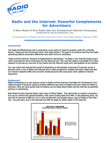
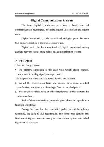
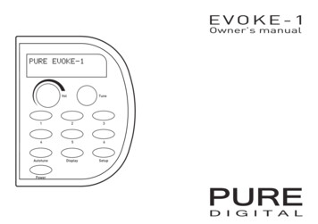
1. Introduction3.1 Industrial facility with fault current sourceThis paper considers the application of pilot protection ondistribution lines. Pilot protection uses communications channelsto send information between relays at each end, and is commonlyused on networked lines. For the purpose of this paper we canassume distribution lines are circuits with an operating voltagetypically between 4 KV and 69 KV. However, the principlesdiscussed in this paper can be applied to any circuit at any voltagelevel, assuming the protection requirements for speed, security,and dependability can be met.As mentioned above, one common example of an effectivelynetworked radial distribution system is the short distribution linethat connects an industrial facility with some generation to autility distribution network. The local generation in the industrialfacility may or may not be large enough to carry the completefacility load, but the generation is a source for short-circuitcurrent on the incoming distribution line and the utility system. Aless common example is an industrial facility with two differentdistribution feeds operating in parallel, where the second utilityfeed can provide short circuit current to the first utility feed. Ineither case, this application typically requires the use of somesort of directional protection, or protection that can identify thefault is on the incoming distribution line. There is only fault currentcontribution from the industrial facility when the local generationis running. The protection scheme must still operate correctlywhen the generation is not running and there is no contributionfrom the plant.The protection challenges for pilot protection of distribution linesare identical to the protection challenges for pilot protectionon transmission lines. The major goal for pilot protection is tooperate dependably for a fault on the protected line and securelyfor faults outside the protected line (Figure 1). One challengeunique to distribution is that the protected line may change froma networked line to radial line quite frequently. If the line is from autility source serving a load with generation capabilities, the lineis only networked while the generation is running.Figure 1.Pilot protection challenge2. Typical applicationsThe majority of distribution systems are radial systems, whichallows the application of time-coordinated overcurrent protectionschemes. While the overall distribution system may be designedas a radial system, individual pieces may be effectively networked.Short distribution lines to industrial facilities with significantgenerating capabilities, or short lines to independent powerproducers, may result in a small networked system. In addition,some parts of the distribution system are intentionally networked,such as in large urban load centers. In these cases, protectionsystem must use a secure method of identifying faults to ensureappropriate isolation of faulted sections of the system. In any ofthese cases, some form of pilot protection is typically applied.Figure 2.Brick - rugged outdoor merging unit3. Protection solutionsThere are a variety of protection schemes for short, networkeddistribution lines. These schemes can be grouped as thoserequiring no communications between line terminals, and as pilotprotection that requires communications between line terminals.The protection schemes that don’t require communications usesome form of directional protection, either directional overcurrentrelays or distance protection. Just as with transmission lineFigure 3.Pilot-wire protection scheme40Application of Digital Radio for Distribution Pilot Protection and Other Applications
applications, directional protection is rarely applied on distributionsystems without pilot communications in order to addressconcerns about coordination, security, and operating time.Pilot protection schemes use some form of communicationsbetween relays at both line ends to ensure secure, selectivetripping. The communications medium used depends on the typeprotection selected, the capabilities of the relay selected, and otherfactors such as cost of installation. Pilot protection methods maysend analog values between relays at each end of the line, or theymay use simple on/off, permissive, or blocking signals betweenrelays at each end of a line.3.1 Pilot-wire protectionOne protection scheme that needs some emphasis is pilot-wireprotection. Pilot-wire relays create a voltage signal to represent themeasured current at the relay location. The pilot-wire relay thensends this voltage via telephone-type copper cable to the relay atthe other end of the line. Pilot-wire relays use the voltages at eachend in voltage differential protection. Pilot-wire relaying thereforerequires only current measurements, is directionally secure, andis very simple to implement and set. Pilot-wire protection was thebest solution from analog, electro-mechanical designs. For thesereasons, pilot-wire protection has been the traditional solution forprotection of short, networked distribution lines serving industrialfacilities.However, the industry is moving away from pilot-wire relayingas a solution for the protection of short, networked distributionlines. This move has little to do with the performance of pilotwire relaying, but has more to do with the general trend towardsdigital relays and the use of digital communications. Oncedigital communications are used, current differential is a betterprotection choice. Digital representation of analog currents canbe sent between each end, on a per-phase basis.3.2 Other common protection methodsOther common protection methods for the short, networkeddistribution line include line differential relaying and pilot protectionschemes such as permissive overreaching transfer trip (POTT)schemes and directional comparison blocking (DCB) schemes. Allof these methods require communications between the relays ateach end of the line. Line differential relaying generally requiresa fiber-optic or other reliable communication channel. Pilotprotection schemes require a communications channel thatcan transmit a binary, on/off, permissive or blocking signal. Thischannel can be a tone sent over an analog telephone line, powerline carrier system, tone over microwave, or fiber-optic cable.But the key piece of all of these protection methods, and a greatchallenge to reliability, is the communications channel. Thecommunication channel must meet application requirements forperformance, reliability, and cost. Performance requirements areclear: the communications channel must be physically capable ofsending the correct type of pilot signal, have enough bandwidth tohandle the signal, and have a short enough system latency time.Reliability requires that the communications channel always beavailable. The channel consists of the actual media used, and anyinterface or conversion devices required between the relay andthe communications channel. This is one of the reasons for thepopularity of pilot-wire relaying. The connection between relaysfor pilot-wire relaying is a physical wiring connection, with noother devices to fail.Cost of equipment, cost of installation, and cost of maintenanceare all important considerations. For a new facility or expansionproject, the cost of installing fiber-optic cable is only an incrementalcost. However, as pilot-wire systems age, and the copper pilotwire degrades and fails, the cost of installation is a larger concern.Installing fiber-optic cable, or even copper cable, in a retrofitinstallation, is very expensive. The equipment costs may wind upas a trivial part of the total project cost.ProtectionMethodData TypeMessageSizeLatencyTimePilot-wirerelayingAnalog (voltage)- 1 msLine differentialrelayingAnalog convertedto digital messageLarge8 msPilot protection(POTT, DCB)Boolean (blockingsignal, permissivesignal)Small8-16 msCommunicationsMediaMetallic pilot-wire pairFiber-opticAnalog telephone lineMicrowave power lineCarrier fiber-opticTable 1.Communications channel requirements4. Digital RadioThe age of modern industrial radio data communicationswas ushered in when it was proven that digital data could beeconomically and reliably transmitted from one device to anotherusing a voice radio set, known as narrow band radio, fittedwith a modem. Packet radio is a term coined by amateur radioenthusiasts that refers to this type of digital radio communicationsequipment. Modern digital radios trace their design heritage backto the days of the first packet radios. Over the years technologicaladvancements in the area of digital radio communications have ledto a wide range of radio equipment for applications ranging fromsimple voice communications to the simultaneous transmission ofmultiple high-speed data channels over a wide band radio link.The attraction of digital radio for protection of short distributionlines is installed cost, particularly in retrofit situations. For shortlines (less than 1 mile in length) with good line of sight betweenline ends, the total equipment costs can be less than 5,000.The installation involves only a small project of around 16 to 24man-hours for design and installation time. The concern overdigital radios is performance. Performance of other communicationmedium and protection applications is well known and wellunderstood by protection engineers. But digital radio is still newto the protection area. So the questions of performance relatedto data types, bandwidth, channel latency, distance, and reliabilitymust be understood.4.1 Data typesCurrently at the physical layer digital radios apply two commoninterface standards: RS485 and 10BaseT Ethernet. The choiceof interface directly impacts the transmission range and type ofradio.InterfaceProtocolBandwidthType ofRadioTypical MaximumDistances10BaseTDNP3 via TCP/IP, ModBus,IEC 618500.5 MBSpreadspectrum:No LicenserequiredUp to approximately 20miles (terrain permitting)10BaseTDNP3 via TCP/IP, ModBus,IEC6 18501.0 MBSpreadspectrum:No LicenserequiredUp to approximately 15miles (terrain permitting)Table 2.Digital radio application guidelinesApplication of Digital Radio for Distribution Pilot Protection and Other Applications41
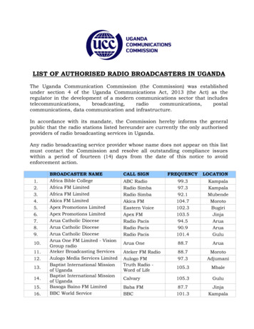
4.2 TerminologyBefore proceeding further it is best to define some common termsthat will be used through the rest of this application note.Spread Spectrum Radios: Radio transmission using the spreadspectrum technique was originally developed to provide jamresistant military communications. Spread spectrum uses amodulation technique that distributes a transmitter’s signal overa very wide bandwidth, making it virtually undetectable to aconventional radio receiver. Frequency Hopping spread spectrumand Direct Sequence spread spectrum are the two primarilymethodologies spread spectrum technology uses to transmitmessages today. Frequency Hopping spread spectrum radios arebetter in environments with interference, and are less likely to bejammed. Direct Sequence spread spectrum radios can supporthigher data bandwidths.Narrow Band Radios: In communications, narrowband is arelative term. From one perspective these voice channel radiosare the modern equivalent of the old packet radios. With baudrates of up to 9.6k they are typically used in SCADA applicationssupporting a single protocol such as DNP or ModBus. They aretypically licensed with up to a 50 mile range.Wide band: In communications, wideband is again a relative term.This term typically applies to radios that have a bandwidth of 200KHz allowing multiple channels of data to be transmitted at thesame time.This paper defines channel latency as the delay between theinitiation of the GOOSE message by the sending relay and thereception of the GOOSE message by the receiving relay. The testactually measures the round-trip channel latency, as one relaymeasures the time between sending the original message andreceiving the echoed response. Of interest for pilot protectionapplications is the one-way channel latency, which is assumed tobe one half of this directly measured round-trip channel latency.4.5 PerformanceThe test was actually a time-based test. The IEC 61850 GOOSEmessages were sent back and forth for some length of time. At theend of the test, 29,672 messages were sent. The test results fromthe 29,672 consecutive messages are recorded in Table 3.Round Trip TimeNo. of Messages 20 ms232Percentage0.78 %20-30 ms29.30398.76 %30-40 ms1270.43 %40-80 ms100.03 %Table 3.Radio performance test resultsAccess Point Radio: The radio that connects the remote radiostogether to form a wireless network. The wireless access point(WAP) usually connects to a wired network, and can relay databetween the remote radios and devices on its wired network.4.3 Digital radio performance testingThe best way to prove digital radio performance for pilot protectionis to test performance under field conditions. The test in this casewas for channel latency and channel reliability. The protectionmessage between each relay is an IEC 61850 GOOSE message.4.4 Application: Pilot protection via IEC 61850GOOSE and spread spectrum radiosThe radios were connected in a point-to-point topology, exactlyas the typical pilot protection application. The test protocolwas a simple matter of measuring the round trip time of eachautomatically generated IEC 61850 GOOSE messages transmittedfrom one relay to another relay and then immediately echoedback to the first relay.Figure 4.Digital radio pilot protection test setupThe typical round-trip time is 20 to 30 ms, meaning the channellatency is 10 to 15 ms. This is very acceptable performance forpilot protection on distribution systems. Therefore digital radiomeets general performance requirements for pilot protectionapplications.4.6 Site installation and commissioningproceduresThe key issue with any communications channel used for protectionis the reliability of the channel, in this case specifically the reliabilityof the radio path. The important factors for digital radio are thedistance between transmitter and receiver, obstructions in the lineof sight between antennas, and the natural environment beneaththe path.Figure 6.Digital radio pilot protection test setup42Figure 5.Fresnel ZoneApplication of Digital Radio for Distribution Pilot Protection and Other Applications
Radio communications is limited to “lineof sight”. However, radio line of sightis longer than the optical line of sightdue to the bending of the radio wavetowards the surface of the earth. Thisradio horizon is typically 30% longer thanthe visual horizon. Therefore, a longercommunications path requires tallerantennas to maintain the line of sight.Digital radio isan inexpensivemethod toLike any other communications channel,proper installation results in desirableperformance. The installation of digitalradio systems requires proper siteselection, an evaluation of path quality,and correct selection and mountingof antennas. The following is a briefoverview of these requirements.provide digitalEvaluating Path QualityObviously, obstructions in the line ofFor optimum radio performance, thesight will impact the performance ofcommunicationsinstallation sites for master and remotethe digital radio, as the strongest radiostations must be carefully considered.signal is communicated directly alongfor pilotSuitable sites should provide:the radio line of sight. As obstructionsblock the width of the radio wave front,protection at the Protection of the radio equipmentless of the signal gets through to thefrom direct weather exposureantennas. Obstructions may also causedistribution levelmulti-path interference due to reflective A source of adequate and stableor refractive signals that may arrive atprimary powerthe receiver out of phase with the desiredsignal. However, due to the diffraction of Suitable entrances for antennathe radio wave, objects not directly inthe line of sight can also act as obstructions. The region where Interface or other required cablingobstructions may impact the performance of the radio wave is Antenna location that provides an unobstructed transmissionknown as the Fresnel zone.path in the direction of the associated station(s).A Fresnel zone (Figure 6) is one of a (theoretically infinite) numberEvaluating Path Qualityof concentric ellipsoids of revolution that define volumes in theradiation pattern of the radio wave. There are multiple FresnelA line-of-sight path is ideal and provides the most reliablezones, but only the first Fresnel zone is important for signaltransmission in all cases. However, minor obstructions in the signalstrength.path will not necessarily block communication but will result insignal attenuation. In general, the need for a clear path becomesIn practice, 60% of the first Fresnel zone must be clear ofgreater as operating frequency and transmission distanceobstructions to allow successful radio communications. Theincreases. Short-range paths (less than 1 mile) can be visuallyradius of the Fresnel zone at its widest point (at the center of theevaluated. Longer distances typically require a path study for newradio line of sight) can be determined by:installations. A path study predicts the signal strength, reliabilityand fade margin of a proposed radio link. While terrain, elevationand distance are the major factors in this process, a path studyWhere b radius of the Fresnel zonemust also consider antenna gain, feedline loss, transmitter power,d distance between transmitter and receiverand receiver sensitivity to arrive at a final prediction.f frequency transmitted in GHZAntenna Selection and orientationBeyond line of sight requirements and Fresnel zone requirements,the other concern with a digital radio path is fading, or theThe single most important item affecting radio performance is theprobability that the radio signal will be lost due to other conditions.antenna system. Careful attention must be given to this part ofThe fade margin determines the allowable signal loss betweenan installation, or the performance of the entire system will bethe transmitter and receiver. The fade margin is a function ofcompromised. High quality, high gain antennas should be used atsystem gains (transmitter power, receiver sensitivity, and antennaall master and remote stations. The antennas should be specificallygain) and system losses (free space loss, losses due to earthdesigned for use at the intended frequency of operation.curvature, coaxial cable loss). Variations in the temperature andCommunication antennas are made by a number ofhumidity of the atmosphere with elevation causes the signals tomanufacturers and fall into two general categories, omnibend more or bend less, resulting in fading at the receiver. Thedirectional, and directional. An omni-directional antenna provideslonger the path, the more likely deep fades will occur, requiring aequal radiation and response in all directions and is thereforegreater fade margin. The local propagation conditions impact theappropriate for use at master stations, which must communicateprobability of signal fade as well. Generally, mountainous terrainwith an array of remote stations scattered in various directions.is favorable, and tropical areas and those near large bodies ofAt remote stations, a directional antenna such as a yagi iswater are unfavorable.typically used. Directional antennas confine the transmission andOne of the losses considered when determining the fade marginreception of signals to a relatively narrow lobe, allowing greateris free space loss. Free space loss is the loss in signal strength ofcommunication range, and reducing the chances of interferencethe radio wave passing through free space. Free space loss is theto and from other users outside the pattern. It is necessary to aimbasic path loss of the system. Free space loss is defined by:these antennas in the desired direction of communication. Theend of the antenna (furthest from the support mast) should faceFree Space Loss 92.4 20 log(f) 20 log(d) dBthe associated station. Final alignment of the antenna headingWhere f frequency in GHzd distance in kmApplication of Digital Radio for Distribution Pilot Protection and Other ApplicationsFigHa43
can be accomplished by orienting it for maximum received signalstrength. Most radio equipment includes provisions for measuringsignal strength.Antenna Mounting ConsiderationsThe antenna manufacturer’s installation instructions must bestrictly followed for proper operation of a directional or omnidirectional antenna. Using the proper mounting hardwareand bracket ensures a secure mounting arrangement with nopattern distortion or de-tuning of the antenna. The followingrecommendations apply to all antenna installations: Mount the antenna in the clear, as far away as possible fromobstructions such as buildings, metal objects, dense foliage,etc. Choose a location that provides a clear path in thedirection of the associated station.Polarization of the antenna is important. Most systemsuse a vertically polarized omni-directional antenna at themaster station. Therefore, the remote antennas must also bevertically polarized (elements perpendicular to the horizon).Cross-polarization between stations can cause a signal lossof 20 decibels (dB) or more.Poor-quality coaxial cables should be avoided, as they will degradesystem performance for both transmission and reception. Thecable should be kept as short as possible to minimize signal loss.For cable runs of less than 20 feet (6 meters), or for short rangetransmission, an inexpensive type such as Type RG-8A/U may beacceptable. Otherwise, use a low-loss cable type suited for 900MHz, such as Heliax .Setting the output powerThe maximum transmitter output power allowed under FCCrules is 30 dBm. The power must be decreased from this levelif the antenna system gain exceeds 6 dBi. The allowable level isdependent on the antenna gain, feedline loss, and the transmitteroutput power setting.NOTE: In some countries, the maximum allowable transmitteroutput may be limited to less than the figures referenced here. Besure to check for and comply with local requirements.Example:To determine the maximum allowable power setting of the radio,perform the following steps:1.Determine the antenna system gain by subtracting thefeedline loss (in dB) from the antenna gain (in dBi). Forexample, if the antenna gain is 9.5 dBi, and the feedline lossis 1.5 dB, the antenna system gain would be 8 dB. (If theantenna system gain is 6 dB or less, no power adjustment isrequired.)2.Subtract the antenna system gain from 36 dBm. The resultindicates the maximum transmitter power (in dBm) allowedunder the rules. In the example above, this is 28 dBm.SWR of the antenna systemFigure 8.Figure 7.Omni-directional antennaYagi antennaThe omni-directional antenna (Figure 7) is a typical antenna thatused at an access point. The above Yagi antenna (Figure 8) isa typical antenna that would be use at a field station. Note thepolarization this antenna is correct if used with either of the aboveomni-directional antennas.FeedlinesThe choice of feedline used with the antenna should be carefullyconsidered.Cable type10 feet50 feet100 feet500 feetRG-2140.76 dB3.8 dB7.6 dBUnacceptableLossLMR-4000.39 dB1.95 dB3.90 dBUnacceptableloss½ inch HELIAX0.23 dB1.15 dB2.29 dB11.45 dB7/8 inch HELIAX0.13 dB0.64 dB1.28 dB6.40 dB1-1/4 inchHELIAX0.10 dB0.48 dB0.95 dB4.75 dB1-5/8 inchHELIAX0.08 dB0.40 dB0.80 dB4.00 dBA proper impedance match between the transceiver and theantenna system is very important. It ensures the maximum signaltransfer between the radio and antenna. The impedance matchcan be checked by measuring the SWR (standing-wave ratio) ofthe antenna system. The reflected power should be less than 10%of the forward power ( 2:1 SWR). Higher readings usually indicateproblems with the antenna, feedline or coaxial connectors. If theresults are normal, record them for comparison for use duringfuture routine preventative maintenance. Abnormal readingsindicate possible trouble with the antenna or the transmission linethat will need to be corrected.4.7 Digital radio and securityOne concern with digital radio is communications security.Traditional communications channels for protection are physicallyisolated from computer networks, and therefore carry little securityrisk. However, digital radio signals are theoretically available toanyone with the proper equipment. Security issues fall into thecategories of protection of privacy, protection from unauthorizedaccess, and protection from denial of service attacks.Protection of privacyUnlicensed spread spectrum radios, such as those suggestedfor pilot protection in this paper, are inherently secure. Spreadspectrum technology was developed during World War II forthe military due to its ability to reject jamming and the difficultyin intercepting transmission. The tools available to hackers toTable 4.Feedline signal loss44Application of Digital Radio for Distribution Pilot Protection and Other Applications
intercept radio frequency messagesare designed for WiFi signals. WiFi is adifferent communications standard thanthat used by digital radio, and these toolswill not intercept digital radio signals.The only practical way to interceptmessages is with a stolen radio. However,all software that operates the radioresides within the radio. This preventscommon hacker tricks such as puttingstolen wireless cards in promiscuousmode. It’s difficult to therefore actuallyretrieve and read the messages usingjust a stolen radio.The attractionof digital radiofor protection ofshort distributionlines is installedcost, particularlypackets over the network. The securityfeatures provided in SNMPv3 are: Message integrity—Ensuring that apacket has not been tampered within-transit. Authentication—Determining themessage is from a valid source. Encryption—Scrambling the contentsof a packet prevent it from beingseen by an unauthorized source.5. Digital Radioin retrofitIn addition, digital radios support AES-128Pilot Performanceor RC4 encryption standards. BothAES-128 and RC4 encryption use a key.situationsComparisonThis key is required to decrypt the data.Unlike earlier encryption technologyWith end-to-end performance in thethe key isn’t static in that it is rotated10 - 15ms range, digital radio immediatelywith other keys after a short period ofplaces itself in the mix of usable pilotoperation. So access to the radio still doesn’t result in access tochannels in the protection and control world. Traditional pilotdata.protection channels include Power Line Carrier, Audio Tone, andmore recently digital channels via fiber (direct or multiplexed) orProtection from unauthorized accesscopper. Although not quite as fast as the total time of direct fiberor a wide-band carrier set (3.5 – 6 ms), it compares quite favorablyThis next level of security assumes that a hacker is alreadyto analog tone over an analog microwave (13 – 18ms) or a digitalconnected to the network using a stolen radio (This is a bigchannel through a modem (15-18ms).assumption). To prevent a break-ins authentication is used toallow the radio access to the network. There are several standardsrevolving ar
access is available (typically at a premium cost), communication based digital protection solutions such as current differential relays and directional overcurrent relays in a pilot protection scheme are used. The modern challenge is a method to provide digital communications for pilot protection that is reliable and affordable.