Transcription
MACH C1500-C2000Rev. 1.02 (3/3/10)MACH GAS-FIRED BOILERC1500 & C2000C.S.A Design-CertifiedComplies with ANSI Z21.13/CSA 4.9Gas-Fired Low Pressure Steam and Hot WaterBoilersASME Code, Section IVCertified by Patterson-KelleyC.S.A Design-CertifiedComplies with ANSI Z21.13/CSA 4.9Gas-Fired Low Pressure Steam and Hot WaterBoilersInstallation Date:Harsco Industrial, Patterson-Kelley100 Burson Street,East Stroudsburg, PA 18301Telephone: (877) 728-5351,Facsimile: (570) 476-7247www.harscopk.com 2010 Harsco Industrial, Patterson-KelleyPrinted : 3/4/2010
MACH Gas-Fired Boiler1.02.0INTRODUCTION. 4SAFETY . 42.1General .42.2Training .42.3Safety Features.52.4Safety Labels .52.5Safety Precautions .63.0INSTALLATION. 83.1Receiving and Storage.83.2Compliance with Codes .83.3Setup .93.4Electrical Connections.103.5Inlet Air and Exhaust Venting.123.6Gas Piping.213.7Boiler Water Piping .233.8Pre-Start Check List .263.9Safety Checks .273.10Initial Adjustments .283.11Burner Adjustment .314.0OPERATION. 344.1General .344.2Normal Lighting and Shut-Down Procedures.344.3Typical Boiler Utility Requirements .355.0MAINTENANCE. 355.1Maintenance and Inspection Schedule .355.2Cleaning the Burner .375.3After All Repairs or Maintenance .375.4Sequence of Operation .385.5Troubleshooting .396.0PARTS/TECHNICAL SUPPORT. 436.1Wiring Diagrams.436.2Boiler Parts List .467.0LIMITED WARRANTY. 508.0MACH BOILER FIRE TEST REPORT. 51APPENDIX 1 – MAINTENANCE LOG . 52APPENDIX 2 – MACH BOILER ALTITUDE DERATE SCHEDULE . 53APPENDIX 3 - MACH WATER CHEMISTRY. 54Page 2
MACH Gas-Fired Boiler!WARNINGImproper use mayresult in fire or injury.Read instructions/safetymanual before installing,operating or servicing boiler.c 1998 HCS, Inc. 800-748-0241Reorder No. 6020-V2WHPKIf the information in this manual is not followed exactly, a fire or explosion may result causing propertydamage, personal injury or loss of life.Do not store or use gasoline or other flammable vapors or liquids in the vicinity of this or any otherappliance.Installation and service must be performed by a qualified installer, service agency, or the gas supplier.It is essential to read, understand, and follow the recommendations of thismanual before installing, operating, or servicing this equipment.Installation and service must be performed by a qualified and knowledgeableindividual who has been trained on the MACH boiler. The same features which permit this boiler toachieve high-efficiency performance make it unlike most other boilers of this general size, so it isimportant to understand how this boiler operates.What to do if you smell gas: Do not try to light any appliance.Do not touch any electrical switch; do not use any phone in your building.Immediately call your gas supplier from a neighbor's phone. Follow the gas supplier's instructions.If you cannot reach your gas supplier, call the fire department.Page 3
MACH Gas-Fired Boiler1.0 INTRODUCTIONThe MACH Gas-Fired Boiler is fully modulating using a variable speed combustion blower, sophisticatedmicroprocessor controls, modulating gas safety shut off / control valves and a unique aluminum alloy heat exchangercapable of operating in a fully condensing mode to provide maximum efficiency in a minimum amount of space. Thehigh-quality materials and thoroughly tested design of the boiler should provide years of trouble-free service if theinstructions in this manual are followed carefully.This manual covers installation of MACH Boilers. The model numbers may be followed by a prefix or suffix letter insome cases to indicate special features or different options.While details may differ slightly, basic operation is the same for all models. Boilers may be built to operate withnatural gas or liquefied petroleum gas (propane). Check the rating plate for correct fuel usage and gas pressures.The boiler is only a part of the complete heating system. This boiler may be fully operational and yet because of poorcirculation, control, or other operating characteristics, not deliver heat to the desired location. Additional equipmentsuch as temperature sensors, pumps, flow switches, balancing valves, and check valves will be required forsatisfactory operation of any system. Harsco Industrial, Patterson-Kelley cannot be responsible for the design oroperation of such systems and a qualified engineer or contractor must be consulted.2.0 SAFETY2.1GENERALThe MACH gas-fired boiler must be: Installed, operated, and serviced in accordance with instructions contained in this manual and other supplementalMACH boiler manuals. Installed by qualified personnel in accordance with designs prepared by qualified facility engineers including:structural, mechanical, electrical, and other applicable disciplines. Operated and serviced in accordance with a comprehensive safety program determined and established by thecustomer. Do not attempt to operate or service until such a program has been established. Operated and serviced by qualified and knowledgeable personnel in accordance with all applicable codes, laws,and regulations.NOTICE!: Each safety device must be maintained and checked per the recommended schedule; refer toSection 5.1 of this manual.2.2TRAININGProper training is the best protection against accidents.It is essential to read, understand, and follow therecommendations of this manual before installing, operating,or servicing this equipment. Failure to do so could result infire or explosion and serious injury, death, and/or propertydamage.Page 4
MACH Gas-Fired BoilerOperating and service personnel must be thoroughly familiar with the basic construction of the MACH boiler C1500or C2000, the use and locations of the controls, the operation of the boiler, adjustment of its various mechanisms, andall applicable safety precautions. If any of the provisions of this manual are not fully and completely understood,contact Technical Service toll free at (877) 728-5351.2.3SAFETY FEATURESIt is the responsibility of the customer to maintain the safety features, such as but not limited to: guards, safety labels,safety controls, interlocks, lockout devices, in place and operable.2.4SAFETY LABELSThe following words are used in this manual to de-note the degree of seriousness of the individual hazards.indicates an imminently hazardous situation which, if not avoided, will result in deathor serious injury. This signal word is to be limited to the most extreme situations.indicates a potentially hazardous situation which, if not avoided, could result in deathor serious injury.indicates a potentially hazardous situation which, if not avoided, may result in minoror moderate injury. It may also be used to alert against unsafe practices.NOTICE/NOTE - NOTICE is the preferred signal word to address practices not related to personal injury. Thesafety alert symbol is not used with this signal word.!WARNINGImproper use mayresult in fire or injury.Read instructions/safetymanual before installing,operating or servicing boiler.c 1998 HCS, Inc. 800-748-0241Reorder No. 6020-V2WHPKThe safety labels shown above are affixed to your boiler. Although the labels are of high quality, they may becomedislodged or unreadable over time. Contact Harsco Industrial, Patterson-Kelley toll-free at (877) 728-5351 forreplacement labels.Page 5
MACH Gas-Fired Boiler2.5SAFETY PRECAUTIONSProvide a suitable location for the boiler, away from normal personnel traffic, with adequate working space, adequateclearances, proper ventilation and lighting, with a structure sufficiently strong and rigid to support the weight of theboiler, all piping, and accessories.2.5.12.5.2Electrical Hazards Shock hazard! Properly lockout/tagout the electrical service and all otherenergy sources before working on or near the boiler. Shock hazard! Do not spray water directly on this boiler or on any electricalcomponents. Electrical hazard! Do not alter wiring connections.Burn, Fire and Explosion Hazards Burn, fire and explosion hazards! Installation must be in strict conformance to all applicablecodes and standards including NFPA 54, ANSI Z223.1 and CAN/CSA B.149.1. Install allrequired vent lines for gas devices. Refer to Section 3.7.1. Hazard from incorrect fuels! Possible fire, explosion, overheating, and damage. Do not useany fuels except the design fuels for the unit.General Warning! Overfire hazards! High pressure in gas or propane supply could result in overfiring of thisappliance or other devices supplied from the same source.WARNINGImproper use mayresult in fire or injury. Fire and explosion hazards! Close the main gas shutoff before servicing boiler.Read instructions/safetymanual before installing,operating or servicing boiler. Fire and explosion hazards! Do not store or use gasoline or other flammable vapors orliquids in the vicinity of this or any other gas fired appliance.c 1998 HCS, Inc. 800-748-0241Hot SurfaceReorder No. 6020-V2WHPK Burn hazard! Possible hot surfaces. Do not touch gas vent during firing operation. Use onlyfactory recommended vent components. Burn hazard! Pipes, vents, and boiler components could be hot. Do not touch piping or stacksurfaces during operation or immediately after shutdown of the boiler. Burn hazard! Hot fluids. Use caution when servicing or draining the boiler. Fire and explosion hazards! Use caution when servicing burner. Propane (LPG) is heavier than air and maylinger in the combustion chamber, vent lines, or elsewhere. Gas leak hazard! Make sure the burner is installed correctly and burner hood is securely fastened following anymaintenance performed on them. These connections cannot be tested after the burner is assembled. Gas leak hazard! All threaded gas connections must be made using a pipe compound that is resistant to liquefiedpetroleum. Do not use Teflon tape on threaded gas piping. Gas leak hazard! Check entire gas train for leaks after installation. If there is a smell of gas, shut down the boilerand obtain immediate assistance from trained service personnel and/or your local fire department. Excess pressure hazard! Possible fire and explosion from excess gas pressure. Make sure that gas inletpressure does not exceed 14 inches W.C. to the regulator. Fire and explosion hazard! Failure to maintain all gas train components may result in malfunction of regulatorsand/or gas safety shut off / control valves. Annual inspection by factory-trained personnel for proper set-up andoperation is recommended. Overfire and underfire hazards! Possible fire, explosion, overheating, and component failure. Do not attempt toadjust firing rate of the boiler. The firing rate must be adjusted only by factory trained personnel.Page 6
MACH Gas-Fired BoilerGas may lose its odor. Proper gas sensing equipment and procedures shouldbe used for leak checks.2.5.3Crush Hazards Lifting hazards! Use properly rated liftingequipment to lift and position the boiler. Theload is unbalanced. Test balance before lifting3 ft. above the floor. Do not allow personnelbeneath the lifted load. Refer to approximateweights in the table below:General Warning 2.5.4Weight in PoundsC15001200C20001400Bump hazard from overhead ductwork and piping. Install components with adequate verticalclearance.Chemical Hazards Chemical hazards from cleaning products. Use caution when cleaning the system. Theuse of professional assistance is recommended. Use safe procedures for the disposal ofall cleaning solutions. Combustion Condensate – an acidic pH of approximately 3.0 to 5.0 can be expected.Use PVC, CPVC, or other corrosion resistant piping for drainage. Collection and disposalmust be in accordance with all applicable regulations. A condensate neutralization kit isavailable. Please contact your local Harsco Industrial, Patterson-Kelley representative.General Warning2.5.5Boiler SizePressure Hazards Pressure hazard! Hot fluids. Install isolation valves on boiler water inlet and outlet.Make sure isolation valves are closed before servicing boiler. Pressure hazard! Hot fluids. Annually test safety relief valve for proper operation. Donot operate boiler with faulty relief valve.General Warning2.5.6Slip, Fall HazardsGeneral Warning Tripping hazard! Do not install piping on floor surfaces. Maintain clear path around boiler. Slip and fall hazard! Use drip pan to catch water while draining the boiler. Maintain dry floorsurfaces. Slip and fall hazard! Do not locate intake or exhaust terminations directly above a walkway;dripping of condensation can cause icing of the walking surface. (see section 3.6.3) Fall hazard! Do not stand on any part of the boiler. Catch hazard! Do not wear rings, jewelry, long hair, loose clothing while working on the boiler.Page 7
MACH Gas-Fired Boiler3.0 INSTALLATIONInstallation and service must be performed by a qualified installer, serviceagency, or gas supplier.3.13.1.1RECEIVING AND STORAGEInitial InspectionUpon receiving the boiler, inspect it for signs of shipping damage. Since some damage may be hidden, werecommend unpacking the boiler, removing the top, front, and side covers and inspect the boiler. Verify that the totalnumber of pieces shown on the packing slip agrees with those actually received.NOTICE! Note any damage, suspected potential damage, or shortage of materials on the freight bill andimmediately notify the carrier. File all claims for shortage or damage with the carrier. Claims for hidden damagesmust be filed with your carrier within 7 days. The boiler carton is equipped with a “Tip (N) Tell”. If "Tip (N)Tell” arrow point is blue, that indicates that the package has been on its side or tipped over in transit.3.1.2Storage Prior to InstallationIf the boiler is not installed immediately, it must be stored in a location adequately protected from the weather andfreezing conditions, preferably indoors. If this is not possible, then it should remain in the shipping container and becovered by a tarpaulin or other waterproof covering.NOTICE! Controls and other equipment that are damaged or fail due to weather exposure are not covered bywarranty.3.2COMPLIANCE WITH CODESThe MACH Boiler with standard components and with many options complies with American National Standard/CSAStandard ANSI Z21.13/CSA 4.9, latest edition, Gas-Fired Low Pressure Steam and Hot Water Boilers.The heat exchanger is constructed and stamped in accordance with ASME Boiler and Pressure Vessel Code, SectionIV for 100 psig maximum operating pressure and/or 200º F maximum temperature.Installation of the boiler must comply with the requirements of all national, state and local codes established by theauthorities having jurisdiction. Authorities having jurisdiction should be consulted before installations are made.Within the US, and in the absence of such local requirements, this boiler should be installed using the National FuelGas Code, ANSI Z223.1/NFPA 54, latest edition.In Canada, the equipment shall be installed in accordance with the current Installation Code for Gas BurningAppliances and Equipment, CAN/CSA-B149, latest edition and applicable Provincial Regulations for the class, whichshould be carefully followed in all cases.Where required by local codes, the installation must conform to American Society of Mechanical Engineers SafetyCode for Controls and Safety Devices for Automatically Fired Boilers (ASME CSD-1).In the Commonwealth of Massachusetts (a) this unit must be installed by a licensed pipe fitter / plumber, (b) fieldinstalled gas cocks must be “T” handle type, (c) piping of condensate shall conform to the State Plumbing Code, and(d) refer to the Massachusetts supplement for further details.Page 8
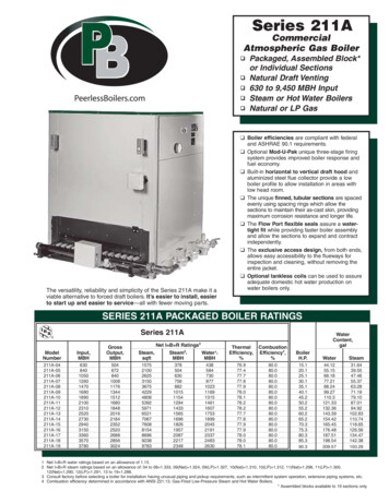
MACH Gas-Fired Boiler3.33.3.1SETUPFoundationProvide a firm, level foundation, preferably of concrete.NOTICE! The boiler may be installed on a combustible floor, however the boiler must never be installedon carpeting.3.3.2PlacementThe wheels provided with this boiler are for positioning purposes only. Whenpositioning this boiler, maintain positive control of it at all times. Do not attempt to move the boiler onsurfaces that are not level. Failure to heed this warning could result in personal injury or death.Lifting the front of the boiler slightly will allow the boiler to be rolled off the shipping skid onto the concrete foundation.Once in position, the wheel bolts may be removed allowing the wheels to recess up into the boiler. The base will sitflat on the provided foundation. If the boiler is to be pulled out for maintenance, the wheels may be left attached.The boiler must be level to function properly. To assist in leveling the boiler, the four (4) adjustable leg bolts (1/2"- 13NC) must be installed. The adjustable legs are also necessary to prevent distortion of the cabinet, (twisting, etc.) inaddition to leveling.Additionally there are three holes in the front and rear of the base that may be used for seismic anchoring.3.3.3ClearancesIf the boiler is to be installed near combustible surfaces, the minimum clearances shown in the pictures and tablebelow must be maintained. Failure to provide for the service access clearances, even with non-combustible surfaces,may cause future problems servicing the boiler. The boiler must be installed in a space large in comparison to theboiler as described in the National Fuel Gas Code, ANSI Z223.1, latest edition.Maintain a clearance from the vent to combustible surfaces of 18” or as specified in the vent manufacturer’s listedinstallation instructions.Minimum Clearances from Adjacent Walls, Ceiling, and Obstructions (shown above &below)DCBDAPage 9D
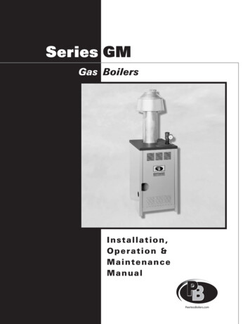
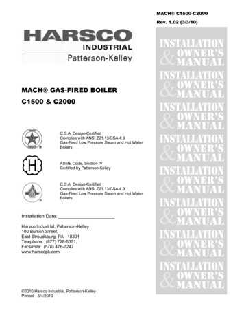
MACH Gas-Fired Boiler† "C" Space required for pipes, ducts, etc. in this area abovethe boiler.Type of SurfaceABC†DCombustible SurfacesMinimum Clearances18181818Recommended ServiceClearances3012*1218*** Clearance depends upon exhaust vent configuration.** Service access is required on left side of boiler to facilitateboiler maintenance. Minimum 2” clearance is required onright side. Do not put pipes, ducts, vents, etc in this space.Electrical conduit must be installed vertically so that the sidedoors can be opened.Dimensions (inches)Bumping hazard from overhead ducts! Install all components with adequatevertical clearances.3.4ELECTRICAL CONNECTIONSThe boiler is wired for 120 volts, single phase, 60 hertz.The total operating amperage is indicated on the ratingnameplate. Each MACH C1500-C2000 boiler requiresless than 15 amps. Before starting the boiler, check toensure that the proper electrical service is connected tothe boiler.An external electrical disconnect (not supplied with theboiler) is required. The boiler electrical service must beinstalled and grounded in accordance with local codes orin the absence of such requirements, in the U.S. withNational Electrical Codes, ANSI/NFPA No. 70 latestedition or, in Canada, to the Canadian Electrical Code,Part I, CSA C22.1, latest edition. Conduit must be installedvertically so that the side doors can be opened.TB2: 120 VoltJunction BoxTB1: Low VoltJunction BoxCustomer Connections for the BoilerViewed from Front of Boiler.NOTICE! A dedicated earth ground (green wire) and neutral is required to avoid nuisance shutdowns.Do not ground through the conduit. It is also important that proper polarity be maintained.The electrical junction boxes are located at the front sides of the boiler. A detailed schematic of the connections isshown in section 6.1.3.4.1High Voltage (TB2) Terminal BlockThe boiler power circuit requires 120 VAC, 60 hertz, with a dedicated neutral and ground as labeled. Electricalservice must be rated for 8 amps minimum. Before starting the boiler, check to ensure that the proper voltage andamperage are connected to the boiler and that the boiler is connected to a suitable fused disconnect switch or circuitbreaker. There must be less than 1.0V from Neutral (TB2-3) to Ground (TB2-8)120VAC Switched Output- This contact closes when the boiler is switched on. This provides 120VAC 5Ampservice to TB2-10. The neutral for this circuit is provided on TB2-3. When the boiler is switched off, this terminal isswitched off as well.3 Way Valve- This output is normally energized, keeping the three way valve providing heat to the building. TheDomestic Hot Water (DHW) call for heat de-energizes this circuit, causing the 3 way valve to self close, therebyPage 10
MACH Gas-Fired Boilerproviding heat to the DHW loop. This output provides 120VAC 0.5Amp service to TB2-11. The neutral for this circuitis provided on TB2-4.DHW Pump Relay w/Delay Off - This output is enabled when there is a call for DHW. When the call for heat isremoved, the output remains enabled for a period of time. This output provides 120VAC 0.5Amp service to TB2-12.The neutral for this circuit is provided on TB2-5.Circ Pump Relay w/Delay Off - This output is enabled when there is a call for heat. When the call for heat isremoved, the output remains enabled for a period of time. This output provides 120VAC 0.5Amp service to TB2-13.The neutral for this circuit is provided on TB2-6.Damper Relay - This output is enabled when the call for heat is enabled. This output provides 120VAC service toTB2-14. The neutral for this circuit is provided on TB2-7. This circuit is for pilot duty only.Master Alarm Relay – This contact closes in the event of an alarm output from the boiler control, connecting TB215 and TB2-16.Flame Detected Relay – This contact closes whenever the boiler is firing, connecting TB2-17 and TB2-18.3.4.2Low Voltage (TB1) Terminal BlockEnable/Disable– TB1-1 and TB1-2 are used for enabling the boiler. Closing this circuit allows the boiler to run.Opening this circuit prevents the boiler from running. This circuit is energized by the boiler. It has a 24VAC potential.Devices connected to these terminals must be rated for 24VACExternal Interlock – TB1-3 and TB1-4 are used for attachment of an additional field safety device to the boilercontrol circuit. Closing this circuit allows the boiler to run. Opening this circuit prevents the boiler from running. Thiscircuit is energized by the boiler with a 5V potential. Devices connected to these terminals must be rated for 5V.Outdoor Temp Sensor – TB1-5 and TB1-6 are connected to the outdoor temperature sensor. The temperaturecontrol must be programmed to run an outdoor air schedule. The outdoor air sensor and programming help areavailable from the local Harsco Industrial, Patterson-Kelley Representative. This circuit is energized by the boiler witha 5V potential. The temperature sensor must be a NTC having 12k@25 C.DHW Stat/Sensor – TB1-7 and TB1-8 are connected to the DHW temperature sensor or thermostat. This circuit isenergized by the boiler with a 5V potential. The temperature sensor must be a NTC having 12k@25 C.Header Temp Sensor – TB1-9 and TB1-10 are connected to the header temperature sensor. This circuit isenergized by the boiler with a 5V potential. The temperature sensor must be a NTC having 12k@25 C.DHW Flow Switch – TB1-11 is energized by the boiler with a 5V potential. This circuit connects through a flowswitch on the domestic side of a domestic hot water system. The flow switch should close upon flow to provide aclosed circuit back to TB1-12.Analog Input– Remote signal for controlling the boiler. The boiler can be operated in a remote setpoint or a remotefiring rate control mode. Input 0-10VDC signal on TB1-13 only. The 0V Analog Input is provided on TB1-14. Thetemperature control must be programmed to run with the analog input.MODBUS – TB1-17 and TB1-18 are used for connecting a MODBUS building management system. (See theENVI Control Advanced Users Guide for more information)Cascade – TB1-19 and TB1-20 are used to connect between boilers that are part of a Master/Member Network. Upto 24 boilers may be connected together. (See the ENVI Control Advanced Users Guide for more information)Page 11
MACH Gas-Fired Boiler3.5INLET AIR AND EXHAUST VENTING3.5.1Applicable Codes & StandardsCODESUnited States:NFPA 54/ANSI Z223.1NFPA/ANSI 211National Fuel Gas CodeChimneys, Fireplaces, Vents and Solid Fuel Burning AppliancesCanadaCAN/CSA B149.1Installation Codes for Gas Burning EquipmentSTANDARDSUL 1738Venting Systems for Gas-Burning Appliances, Categories II, III, and IVULC S636-95Standard for Type BH Venting SystemsSheet Metal andThermoplastic Duct Construction ManualAir Conditioning Contractors National Association (SMACNA)These codes and standards contain information for the venting of gas fired appliances, including, but not limited tovent sizing, location, clearance to combustibles, and safe installation practices. The installation must comply withboth the above Federal Codes and with state, provincial and local codes.Design and installation of venting systems should be done only by qualified andknowledgeable venting systems personnel and in accordance with vent system manufacturer’sinstallation instructions. Installing a boiler or vent system using improper installation methods ormaterials can result in serious injury or death due to fire or asphyxiation.Before connecting a boiler to a venting system, it must be determined whetherthe boiler is to be installed in a conventional or Direct Vent configuration. In the US, provisions forcombustion and ventilation air must be in accordance with NFPA 54/ANSI Z223.1, National Fuel GasCode, latest edition, or applicable provisions of the local building codes. In Canada, combustion andventilation air openings shall comply with CAN/CSA B-149.1 Natural Gas and Propane Installation Code.For correct installation of vent system, read all of these instructions and refer tovent manufacturer’s instructions.Failure to use a proper vent system (types and materials), as described in this manual will void the boilerwarranty and may result in rapid deterioration of the venting system, creating a health or life safetyhazard.Faulty vent installation can allow toxic fumes to be released into living areas. This may cause propertydamage, serious bodily injury or death.3.5.1.1 Gas Vent CategoriesSeveral codes and standards have categorized appliances in accordance with the flue gas temperature and pressureproduced by the appliance. Categories are defined as follows: Category I An appliance that operates with a non-positive vent static pressure and with a vent temperature Category II An appliance that operates with a non-positive vent static pressure and with a vent temperature Category III An appliance that operates with a positive vent static pressure and with a vent temperaturethat avoids excessive condensate production in the v
2010 Harsco Industrial, Patterson-Kelley Printed : 3/4/2010 MACH GAS-FIRED BOILER C1500 & C2000 Installation Date: _ Harsco Industrial, Patterson-Kelley 100 Burson Street, East Stroudsburg, PA 18301 Telephone: (877) 728-5351, Facsimile: (570) 476-7247 www.harscopk.com MACH C1500-C2000 .