Transcription
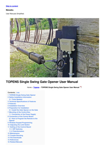
Automatic Gate OperatorInstallation Manualfor models:Warning: Before installing your PolarisAutomatic Gate operator (sometimes alsoreferred to as the “Product”), read this entireInstallation Manual for information about Productsafety matters and proper use of the Product.Only use the Product for the purpose ofoperating a driveway gate.POLARIS 700/702POLARIS 500/502
WARNING OF RISKS, PURCHASER’S RESPONSIBILITIES, AND ASSUMPTION OF CERTAIN RISKS:The directions for installation and use of the Product must be followed carefully. It is impossible to eliminate all risks inherentlyassociated with use of the Product. The effectiveness of the Polaris Automatic Gate Operator depends on proper installation andthe manner of use or application, all of which are beyond the control of Polaris Professional Products or the seller. All such risks areassumed by the purchaser, and by the purchaser’s installation and use of the Product.The Polaris Automatic Gate Operator is for use on driveway gates only. The Product meets or exceeds the requirements of UL 325,the standard that regulates gate operator safety, as established and made effective March 14, 2003, by Underwriters Laboratories,Inc.
TABLE OF CONTENTSGate Operator Class Categories . . . . . . . . . . . . . . . . . . . . . . . . . . . . . . . . . . page 4Warnings and Precautions . . . . . . . . . . . . . . . . . . . . . . . . . . . . . . . . . . . . . . . page 5Pull-to-Open Gate Operator Mounting . . . . . . . . . . . . . . . . . . . . . . . . . . . page 8Push-to-Open Gate Operator Mounting . . . . . . . . . . . . . . . . . . . . . . . . . page 12DIP Switches . . . . . . . . . . . . . . . . . . . . . . . . . . . . . . . . . . . . . . . . . . . . . . . . . . . page 16Wiring Operator . . . . . . . . . . . . . . . . . . . . . . . . . . . . . . . . . . . . . . . . . . . . . . . .page 18Pull-to-Open Limit Setting . . . . . . . . . . . . . . . . . . . . . . . . . . . . . . . . . . . . . .page 23Push-to-Open Limit Setting . . . . . . . . . . . . . . . . . . . . . . . . . . . . . . . . . . . . . page 25Obstruction Sensitivity Set Up . . . . . . . . . . . . . . . . . . . . . . . . . . . . . . . . . . page 27Primary/Secondary Gate Movement . . . . . . . . . . . . . . . . . . . . . . . . . . . . page 28Transmitter/Receiver . . . . . . . . . . . . . . . . . . . . . . . . . . . . . . . . . . . . . . . . . . . page 29Accessory Hook Up Diagram . . . . . . . . . . . . . . . . . . . . . . . . . . . . . . . . . . . .page 30Exit Wand Hook Up Diagram . . . . . . . . . . . . . . . . . . . . . . . . . . . . . . . . . . . .page 33Photo Eyes Hook Up Diagram . . . . . . . . . . . . . . . . . . . . . . . . . . . . . . . . . . .page 34Emergency Disconnect . . . . . . . . . . . . . . . . . . . . . . . . . . . . . . . . . . . . . . . . . page 36Technical Specifications . . . . . . . . . . . . . . . . . . . . . . . . . . . . . . . . . . . . . . . . page 37Parts List and Illustrations . . . . . . . . . . . . . . . . . . . . . . . . . . . . . . . . . . . . . . .page 38Troubleshooting/Maintenance . . . . . . . . . . . . . . . . . . . . . . . . . . . . . . . . . .page 40Programming Wireless Keypad . . . . . . . . . . . . . . . . . . . . . . . . . . . . . . . . . .page 42List of Accessories . . . . . . . . . . . . . . . . . . . . . . . . . . . . . . . . . . . . . . . . . . . . . . page 43Warranty . . . . . . . . . . . . . . . . . . . . . . . . . . . . . . . . . . . . . . . . . . . . . . . . . . . . . . .page 44Polaris Automatic Gate Operators608 Tierra Montana LoopBernalillo, NM 87004Phone: 505-404-2222Fax: 800-830-3952Email: ask@polarisgate.comWeb: www.polarisgate.com
GATE OPERATOR CLASS CATEGORIESGate operator CLASSCATEGORIES*Residential Vehicular Gate Opener–Class I: A vehiculargate opener (or system) intended for use in a homeof one-to-four single family dwelling, or a garage orparking area associated therewith.FOR YOUR RECORDSPlease record the serial number(found on the control box cover)and purchase information below.Keep this with yourproof of purchase (receipts) in case yourproduct is lost, stolen or requires service.Light Commercial/General Access Vehicular Gate Opener–Class II: A vehicular gate opener (or system) intended for usein a commercial location or building such as a multifamilyhousing unit (five or less single family units), hotel, garages,retail store or other building servicing the general public.Serial number:Purchase date:Retailer/store name:The Polaris Automatic Gate Operator is intended for use withvehicular swing gates. The operator can be used in Class I,Class II, Class III, and Class IV applications.Industrial/Limited Access Vehicular Gate Opener–Class III:A vehicular gate opener (or system) intended for use in anindustrial location or building such as a factory or loadingdock area or other locations not intended to service thegeneral public.Restricted Access Vehicular Gate Opener–Class IV: Avehicular gate opener (or system) intended for use ina guarded industrial location or building such as anairport security area or other restricted access locationsnot servicing the general public, in which unauthorizedaccess is prevented via supervision by security personnel.*Categories established by Underwriters Laboratories forvehicle gate operatorsPolaris is a high end residential gate operator. Also suited forlight commercial / industrial applications. Not advised forcontinuous duty.Customer Service8:00am to 5:00pm, MST, Monday – FridayPolaris Gate Operators608 Tierra Montana Lp.Bernalillo, NM 87004Phone: 505-404-2222 Fax: 800-830-3952;Email: techsupport@polarisgate.com4
WARNINGS AND PRECAUTIONSWARNINGS AND PRECAUTIONSSafety overview checklist:WARNING – To reduce the risk of injury or death:General Safety Information SAVE THESE INSTRUCTIONSThe Polaris Automatic Gate Operator is designed to providefor safe operation. One of the most important safety featuresof the gate operator is obstruction sensing. When thereis an obstruction that prevents the gate from opening orclosing, the gate will immediately reverse direction andreturn to the fully open or closed position. While in theprocess of returning to the fully open or closed position, ifthe gate senses an additional obstruction the gate will stopimmediately and sound an alarm. At this point the gateoperator will need to be reset by turning the power switchon the control box OFF for a minimum of ten seconds. Use this operator only with swing gates. READ AND FOLLOW ALL INSTRUCTIONS. Never let children operate or play with gate controls.Keep the remote control away from children. Always keep people and objects away from the gate.NO ONE SHOULD CROSS THE PATH OF THE MOVINGGATE. The entrance is for vehicles only. Pedestrians must use aseparate entrance. Remember that the Polaris Automatic Gate Operatormust only be installed on gate systems meeting therequirements of the application. Ensure that you are using the correct gate operator forthe type and size of gate, its frequency of use and theclass rating. Ensure that the gate and gate operator installationcomply with applicable local codes. Contact local fire and law enforcement to arrangeemergency access procedures. Keep people, animals, and property away from thegate area. Do not let children play in or near the gatearea. Use caution with moving parts to avoid injuring fingersor hands. Consider installing contact sensors, or non-contactsensors to provide additional safety and protectionagainst entrapment. Never activate the gate operator until you ensure thatthe area is clear of people, pets, or other obstructions.Watch the gate until it stops. Controls must be far enough from the gate so that theuser is prevented from coming in contact with the gatewhile operating the controls.The Polaris gate operator includes an adjustment for settingthe sensitivity of the obstruction performance. Refer to page27 for Obstruction Sensitivity Set Up details.Vehicular gates are large heavy objects. Polaris Automaticgate operators provide a convenient way to open and closethe gates. Since the gate system and its components exerta high level of force to open and close the gate, they canbe dangerous, causing severe injuries or death to you andothers.Your safety and the safety of others depend on theinstaller of this system to read, understand, and followthe information and instructions in this manual.The Polaris Automatic Gate Operator is designed to complywith UL 325, the safety standard covering automatic gateopening systems. UL 325 requires that gate openingsystems have provisions for, or be supplied with, at leastone independent primary and one independent secondarymeans of protection against entrapment. The primarymeans of entrapment protection in the Polaris AutomaticGate Operator is Type A, an inherent means of entrapmentprotection. The secondary means of entrapment protectionin the Polaris Automatic Gate Operator is Type B1, theprovision for the connection of a photo cell or other noncontact sensor.The gate operator’s built-in means of entrapmentprotection (Type A) may not be sensitive enough toprevent bodily injury in some circumstances. Secondarymeans of entrapment protection (Type B1), such as aphoto cell are suggested for enhanced safety.5
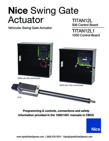
WARNINGS AND PRECAUTIONSProtection against EntrapmentImportant! Study fig. 1 and keep safety foremost at alltimes.Entrapment areas for a proper pull-to-open installationEntrapment Area 1Hinged edge of the gate and the fence postEntrapment Area 2Between the gate and the gate postEntrapment Area 3The path of the gateEntrapment Area 4The space between the gate in the open position andany object such as a wall, fence, tree, etc.Entrapment Area 5Pinch points between the operator and gate or postArea 1Figure 1FenceFenceArea 2Area 5Area 3Area 4Gate in open positionDriveway6
WARNINGS AND PRECAUTIONSEntrapment AlarmWarning Signs and Labels(UL 325; 30.1)In compliance with UL 325 the Polaris Automatic GateOperator is designed to stop and reverse direction withintwo seconds of sensing an obstruction. In addition, thePolaris Automatic Gate Operator activates an audiblealarm if the unit incurs an obstruction twice while openingor closing. This alarm sounds for five minutes, or untilthe operator receives a renewed, intended input from ahardwired control such as the Push Button Control. At thatpoint the gate returns to a fully open or fully closed position.Turning the power switch on the control box OFF for tenseconds and back ON also deactivates the alarm.Required Safety Precautions for GatesWarning signs alert people of automatic gate operation.They are required when installing the Polaris Automatic GateOperator. If pedestrians will be in the area, install a walkthrough gate for their use.Figure 2Warning SignsThe warning signs must be installed on both sides of thegate.These warning signs and decals must be used. If anywere missing when the gate operator was purchased,immediately contact Polaris Automatic Gate Operators forreplacements.Warning signs (two enclosed) to be installedon each side of the gate (three to five feetabove the bottom of the gate)Figure 3Install warning decals,one on each side of gateoperator7
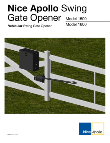
PULL-TO-OPEN GATE OPERATOR COLUMN MOUNTINGFigure 4PULL-TO-OPEN GATE OPERATOR COLUMNMOUNTING MEASUREMENTSy(Open gate to inside of property)The proper position of the mounting brackets is crucialto the efficiency and leverage of the gate operator. Thedistance between the gate operator and the gate is alsodetermined by the proper position of the mountingbrackets.XNOTE: Gate operator should be in the fully retracted positionbefore attaching the gate bracket and the post mountbracket assembly.NOTE: Make sure the actuator can swing freely through thecomplete travel of the gate. Please contact our TechnicalSupport dept. to discuss “X” - “Y” measurement needed foryour installation of the Polaris 500 or 700 series operators tocolumn mount applications.NOTE: Gate in OPEN position8
PULL-TO-OPEN GATE OPERATOR MOUNTINGStep 1The post bracket and pivot bracket are installed as shownin fig. 5. **Note - If using supplied brackets for an AmazingGate System with posts, please refer to installationinstructions provided with your Amazing Gate.***Figure 5Post3/8” – 16 x 3” Hexbolt1/2” – 13 Hex1/2” Flat washerPost bracket3/8” – 16 x 10” Carriage orall thread boltPivot bracket3/8” Flat washer3/8” – 16 Hex nutGate bracketStep 2The gate bracket is installed as shown in fig. 6.3/8” Flat washerFigure 63/8” – 16Hex nut3/8” – 16 x 3”Hex bolt9Gate
PULL-TO-OPEN GATE OPERATOR MOUNTINGStep 3With the gate in the desired open position and withthe gate operator in its fully retracted position, installthe gate operator. Ensure the gate operator is mountedlevel.Figure 73/8” – 16 x 3”Hex bolt3/8” x 2 3/8”Clevis pin3/8” x 1 3/8”Clevis pin3/8” Flat washer3/8” – 16 Hex nut3/8” x 1 1/8” OD x1/2” BushingClevis pin clip103/8” x 1 1/8” OD x3/32” BushingClevis pin clip
PULL-TO-OPEN GATE OPERATOR MOUNTINGFigure 8Step 4Ensure a minimum 2” space exists between the gateand the gate operator for safety reasons. If the properclearance cannot be achieved, you may need to movethe post mount bracket assembly slightly to the right orleft to obtain the proper clearances.FenceNOTE: Ensure the gate operator and the pivot bracketdoes not bind in the gate-open and gate-closed positions.2” MinimumNOTE: Gate inOPEN positionPinch areaNOTE: Gate inCLOSED positionPinch area2” MinimumFenceFigure 9Mounting the Control BoxStep 5Mount the control box as illustrated.NOTE: Ensure the control box is mounted to a securesurface and at least three feet above the ground toprotect it from rain, snow, and other conditions.Control Box Dimensions:14.5h x 12.5w x 10.5d#10 x 2”Mounting screwsMounting of Secondary OperatorIf mounting two operator arms on a dual gate, repeatsteps 1 – 4 for the secondary operator arm.Control box11
PUSH-TO-OPEN GATE OPERATOR MOUNTINGPUSH-TO-OPEN GATE OPERATORMOUNTING(Open gate to outside of property)For push-to-open applications, a push-to-open pivotbracket should be used. This bracket must be purchasedseparately (see List of Accessories).The proper position of the mounting brackets is crucialto the efficiency and leverage of the gate operator. Thedistance between the gate operator and the gate is alsodetermined by the proper position of the mountingbrackets.NOTE: Gate operator should be in the fully retracted positionbefore attaching the gate bracket and the post mountbracket assembly.Figure 10yXNOTE: Gate in CLOSED positionX 6 inchesY 8 3/8 inchesNOTE: These dimensions provide optimal performance.Deviation from these dimensions will reduce speed orpower to the extent the operator may not functioncorrectly.12
PUSH-TO-OPEN GATE OPERATOR MOUNTINGStep 1The post bracket and pivot bracket are installed as shownin fig. 11. **Note - If using supplied brackets for an AmazingGate System with posts, please refer to installationinstructions provided with your Amazing Gate.***Figure 11Post3/8” – 16 x 3” Hexbolt1/2” – 13 Hex1/2” Flat washerPost bracket3/8” – 16 x 10” Carriage boltor all-thread bolt.Push-to-Open PivotBracket (not included)3/8” Flat washer3/8” – 16 Hex nutGate bracketFigure 123/8” Flat washer3/8” – 16Hex nutStep 2The gate bracket is installed as shown in fig. 12.3/8” – 16 x 3”Hex bolt13Gate
PUSH-TO-OPEN GATE OPERATOR MOUNTINGStep 3With the gate in the desired closed position and withthe gate operator in its fully retracted position, installthe gate operator. Ensure the gate operator is mountedlevel.Figure 133/8” – 16 x 3”Hex bolt3/8” x 2 3/8”Clevis pin3/8” x 1 3/8”Clevis pin3/8” Flat washer3/8” – 16 Hex nut3/8” x 1 1/8” OD x1/2” BushingClevis pin clip143/8” x 1 1/8” OD x3/32” BushingClevis pin clip
PUSH-TO-OPEN GATE OPERATOR MOUNTINGStep 4Ensure a minimum 2” space exists between the gateand the gate operator for safety reasons. If the properclearance cannot be achieved, you may need to movethe post mount bracket assembly slightly to the right orleft to obtain the proper clearances.Figure 14NOTE: Ensure the gate operator and the pivot bracketdoes not bind in the gate-open and gate-closed positions.NOTE: Gate inOPEN position2” MinimumFenceNOTE: Gate inCLOSED positionPinch areaPinch area2” MinimumFenceFigure 15Mounting the Control BoxStep 5Mount the control box as illustrated.NOTE: Ensure the control box is mounted to a securesurface and at least three feet above the ground toprotect it from rain, snow, and other conditions.#10 x 2”Mounting screwsMounting of Secondary OperatorIf mounting two operator arms on a dual gate, repeatsteps 1 – 4 for the secondary operator arm.Control box15
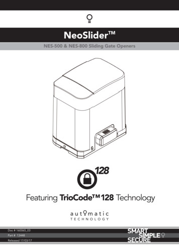
DIP SWITCHESDIP SWITCHESFigure 16DIP SwitchesBlock 2* - Default factory settingBlock 1, DIP Switch 1 – Auto CloseON – Auto close feature enabledOFF* – Auto close feature disabledNOTE: To adjust auto close time refer to figure 17.Block 1, DIP Switch 2 – Audible Motion AlarmON – Audible motion alarm enabledOFF* – Audible motion alarm disabledBlock 1Block 1, DIP Switch 3 – Extended Soft Start/StopON – Extended soft start/stop operation enabledOFF* – Normal soft start/stop operationNOTE: All DIP Switches areshown in the factory defaultposition (OFF)Block 1, DIP Switch 4 – Time of Soft Start/StopON – Max. extended time of soft start/stop operationOFF* – Extended time of soft start/stop operationNOTE: Only active if Block 1, DIP 3 is set to ONBlock 2, DIP Switch 1 – Single or Dual GateON – Dual gate applicationsOFF* – Single gate applicationsBlock 2, DIP Switch 2 – Pull-to-Open or Push-to-Openfor Primary Gate OperatorON – Primary gate operator set up for push-to-openoperationOFF* – Primary gate operator set up for pull-to-openoperationBlock 2, DIP Switch 5 – Sequencing of Dual GateOpening and ClosingON – Secondary gate operator opens first and closessecond (2 second delay)OFF* – Primary gate operator opens first and closessecond (2 second delay)NOTE: Only active if Block 2, DIP 4 is in the ON positionBlock 2, DIP Switch 3 – Pull-to-Open or Push-to-Openfor Secondary Gate OperatorON – Secondary gate operator set up for push-to-openoperationOFF* – Secondary gate operator set up for pull-to-openoperationNOTE: Only active if Block 2, DIP Switch 1 is set in theON positionBlock 2, DIP Switch 6 – Dual Gate Position LimitSettingsON – Set limit setting for secondary gate operatorOFF* – Set limit setting for primary gate operatorNOTE: Only active if Block 2, DIP Switch 1 is set in theON positionBlock 2, DIP Switch 4 – Timing of Dual GatesON – One gate is delayed when opening or closingOFF* – Gates open and close simultaneouslyNOTE: Only active if Block 2, DIP Switch 1 is set in theON positionBlock 2, DIP Switch 7 – Constant or MomentaryPressureON – Constant pressure required to operate gateOFF* – Momentary contact required to operate gateBlock 2, DIP Switch 8 – Not Used16
DIP SWITCHESAuto Close TimerThe amount of time between opening the gate andautomatically closing the gate can be adjusted between0 seconds and 120 seconds. The adjustment is made byturning the CLOSE TIMER potentiometer. The defaultposition of the potentiometer is zero seconds. Timer willactivate after gates have completed one full cycle.To increase the delay time, turn the potentiometerclockwise.NOTE: Only active if Block 1, DIP switch 1 is in the ONposition.Figure 17Auto Close Potentiometer17
WIRING OPERATORWIRING OPERATORFigure 18Location ofON/OFF SwitchNOTE: Before powering, gate operator must be connectedto the control box – damage may occur if gate operatoris connected directly to a battery or other power source.Step 1Ensure the control box power switch is in the OFFposition. The control box power switch is located on thebottom of the control box.NOTE: Use only 16 gauge dual conductor, multi-stranded,direct burial wire for AC power hookup. Follow localelectrical codes.Control BoxStep 2If using AC power to charge the battery, connect wire to thecontrol box as shown in fig. 19.If charging battery with a solar panel(s), refer to AccessoryHook-Up Diagram fig. 32 on page 28.Connect wires from primary operator (and secondaryoperator if installing on a dual gate) to the control box asshown in fig. 19. Wire should be buried in accordance withlocal codes.ON positionOFF positionWARNING: DO NOT CONNECT BOTH TRANSFORMER ANDSOLAR PANEL. THIS SYSTEM IS DESIGNED TO RUN ON ONLYONE POWER SOURCE. CONNECTING BOTH POWER SOURCESCAN RESULT IN DAMAGE TO CIRCUIT BOARD AND WILL VOIDWARRANTY.Figure 19Figure 20YelBrnRedBlkBluBlkBluBrnRedTerminal blockScrew in connectorto lock wire in placeYelOrgOrgTransformerWireNOTE: Unscrew connector torelease wirePrimaryGate OperatorSecondaryGate Operator18NOTE: Entire terminal block canbe removed from circuit board toallow wiring. The terminal blockcan then be snapped back ontothe circuit board
WIRING OPERATORFigure 21Step 3The transformer provided is for dry location use only. If usedin an outside outlet, the transformer must be enclosed orcovered for weather protection. Attach AC power wire to thetransformer.NOTE: DO NOT PLUG TRANSFORMER INTO AC POWERUNTIL ALL WIRING IS COMPLETED.Step 4Install the battery by placing the battery into the controlbox. The control box can accommodate one or two batteries.Warning: Do not attempt to splice operator wires forthe purpose of extending your wiring connections. Doingso can void your warranty. Contact technical support forrecommended procedure. 1-800-234-3952.BatterySecond battery (not included)Figure 22Step 5Connect the battery terminal wiresto the battery.Step 6Plug in transformer. Turn controlbox power switch to the ONposition.Black (-) terminal wireRed ( ) terminal wire19
WIRING OPERATORBoard Layout DescriptionFigure ons1. 18 VAC Power2. 24V Converter3. Gate Operator Retracting4. Gate Operator Extending5. Obstruction6. Auto Close7. Battery OK8. Battery Charging9. Status10. Safety Loop11. Shadow Loop12. Exit Loop13. Radio Receiver16. Cycle – used as an input device17. Set Limit18. Learn Code19. Power SaveFuses20. 15 amp Fuse21. 4 amp FuseConnectors22. Buzzer Connection23. RF Board ConnectionPotentiometers14. Stall Force Adjustment15. Auto Close Adjustments2013
WIRING OPERATORLED DescriptionsPower Save Mode (Recommended for SolarApplications)Proper wiring and performance can be verified by checkingthe operation of the LED’s located on the circuit board.Polaris Automatic Gate Operators come equipped with aPower Save feature. The default mode is for all LED’s to beoperational as described. If it is desired to conserve power tomaximize battery life (recommended for the following stepscan be taken.LED #1: 18VAC OKLit when AC power is being supplied to the circuit board.LED #2: 24V OKLit when 24V converter is activated.Press and hold the PWR SAVE button for three seconds.An audible beep will sound confirming the change tothe power save mode. This will disable several LED’swhen not activated for five minutes. In Power Savemode, the LED’s will operate as described upon aninput. When the gate sits idle for five minutes, the LED’swill turn off to conserve power.LED #3: INThere are two “IN” LED’s. One near the Opener 1 terminalsand one near the Opener 2 terminals. One LED will lightwhen a single gate operator is retracting. Both LED’s will lightwhen dual gate operators are retracting.LED #4: OUTThere are two “OUT” LED’s. One near the Opener 1terminals and one near the Opener 2 terminals. One LEDwill light when a single gate operator is extending. BothLED’s will light when dual gate operators are extending.When troubleshooting the installation it isrecommended to disable the Power Save feature. Thefeature can be disabled by pressing and holding thePWR SAVE button for three seconds. Two audible beepswill sound confirming the change to normal modeoperation.LED #5: OBSTRLit when an obstruction is sensed.Figure 24LED #6: TIMER ONBlinks when auto close feature is enabled and gate isin open position. Lit when gate arm cycle limiter isautomatically activated.LED #7: BATT OKLit when battery is OK or “charged.”LED #8: CHARGINGLit when battery is being charged.LED #9: STATUSBlinks to indicate that the system is functioning properly.Also used to indicate a user input during installation.Power save buttonLED #10: SAFETY LOOPLit when the safety loop contact is made.LED #11: SHADOW LOOPLit when shadow loop contact is made.LED #12: EXIT LOOPLit when an exit loop contact is made.LED #13: RADIO RECVRLit while transmitter button is pushed.21
WIRING OPERATOR22
PULL-TO-OPEN LIMIT SETTINGPULL-TO-OPEN LIMIT SETTINGFigure 27(Open gate to inside of property)Single Gate InstallationsStep 1Make sure the gate is in the fully open position.Ensure power switch is in the ON position.Step 2Verify Block 2, DIP Switch #1 is in OFF position. Press thecycle button on circuit board and the gate will begin toclose. Stop the gate using the cycle button when the desiredlimit has been reached.Step 3Press and hold the “SET LIMIT” button until one audiblebeep is heard to acquire the closed limit setting. The STATUSlight will turn on immediately upon pressing the SET LIMITbutton. The STATUS light will turn off and an audible beepwill verify the closed limit is now set.Step 4Press cycle button on circuit board to return the gate to thefully open position.Step 5Again, using the cycle button close the gate to verify itmeets the desired location. If the gate did NOT reach thedesired closed limit, proceed to step 6.WARNING: Do not use hand heldtransmitters to program primaryand secondary limits. Only thecycle button should be used untilfinal set up is complete to avoiddamage to actuators and voidingwarranty.Step 6CLEARING THE CLOSED LIMIT SETTING:a) Return the gate to the fully open position.b) Press and hold the SET LIMIT button until two audiblebeeps are heard.c) Two audible beeps will verify the closed limit setting isnow cleared.Repeat steps 1 – 5 to program the gates “closed limitsetting”.***Dip switch number 6 dictates which gate is beingaffected by the set limit button, whether setting orclearing the limit. If dip switch 6 is in the up position, itwill set or clear the limit for the secondary operator. Ifit’s in the down position it will set ot clear the limit forthe primary operator.***23
PULL-TO-OPEN LIMIT SETTINGDual Gate InstallationsFigure 28Step 1Make sure both gates are in the fully open position.Ensure power switch is in the ON position.Step 2Verify Block 2, DIP Switch #1 is in ON position. Press the cyclebutton on the circuit board and the gates will begin to close.Stop the gates using the cycle button when the desired limitfor the primary gate has been reached.Step 3Verify Block 2, DIP Switch #6 is in the OFF position. Pressand hold the “SET LIMIT” button until one audible beep isheard to acquire the closed limit setting (fig. 28). The STATUSlight will turn on immediately upon pressing the SET LIMITbutton. The STATUS light will turn off and an audible beepwill verify the closed limit is now set.Step 4Press the cycle button on circuit board to return the gates tothe fully open position.Step 5 (setting secondary gate)Set Block 2, DIP switch #6 to the ON position. Again, pressthe cycle button. The gates will begin to close. The primarygate should stop at the closed limit position that wasprogrammed in the previous steps. The secondary gate willcontinue to close until you press the cycle button on thecircuit board.Step 6Press and hold the “SET LIMIT” button until one audiblebeep is heard to acquire the closed limit setting (fig. 28). TheSTATUS light will turn on immediately upon pressing the SETLIMIT button. The STATUS light will turn off and an audiblebeep will verify the closed limit is now set.Step 8CLEARING THE CLOSED LIMIT SETTINGS:a) Return the gates to the fully open position.b) Set Block 2, DIP switch #6 to the OFF position.c) Press and hold the SET LIMIT button until two audiblebeeps are heard.Two audible beeps will verify the closedlimit setting is now cleared.d) Set Block 2, DIP switch #6 to the ON position.e) Press and hold the SET LIMIT button until two audiblebeeps are heard. Two audible beeps will verify the closedlimit setting is now cleared.Step 7Press the cycle button on circuit board to open both gates.Then once again press the button to close the gates andverify the closed limits are set properly. If the gates did notreach the desired closed limits, proceed to step 8.Repeat steps 1 – 7 to program the gates “closed limitsetting”.24
PUSH-TO-OPEN LIMIT SETTINGPUSH-TO-OPEN LIMIT SETTINGFigure 29(Open Gate to Outside)Single Gate InstallationsStep 1Make sure the gate is in the fully closed position.Ensure power switch is in the ON position.Step 2Verify Block 2, DIP Switch #1 is in OFF position and Block 2,DIP switch 2 is in the ON position.Press the cycle button on circuit board and the gate willbegin to open. Stop the gate using the cycle button whenthe desired limit has been reached.Step 3Press and hold the “SET LIMIT” button until one audiblebeep is heard to acquire the open limit setting. The STATUSlight will turn on immediately upon pressing the SET LIMITbutton. The STATUS light will turn off and an audible beepwill verify the open limit is now set.Step 4Press cycle button on circuit board to return the gate to thefully closed position.Step 5Again, using the cycle button open the gate to verify itmeets the desired location. If the gate did NOT reach thedesired open limit, proceed to step 6.WARNING: Do not use hand heldtransmitters to program primaryand secondary limits. Only thecycle button should be used untilfinal set up is complete to avoiddamage to actuators and voidingwarranty.Step 6CLEARING THE OPEN LIMIT SETTING:a) Return the gate to the fully closed position.b) Press and hold the SET LIMIT button until two audiblebeeps are heard.c) Two audible beeps will verify the open limit setting isnow cleared.Repeat steps 1 – 5 to program the gates “open limitsetting”.25
PUSH-TO-OPE
Light Commercial/General Access Vehicular Gate Opener- Class II: A vehicular gate opener (or system) intended for use in a commercial location or building such as a multifamily housing unit (five or less single family units), hotel, garages, retail store or other building servicing the general public. Industrial/Limited Access Vehicular Gate .