Transcription
Grid-Connected SolarMicroinverter ReferenceDesign 2010 Microchip Technology Incorporated. All Rights Reserved.Grid Connected Solar Microinverter Reference Design using the dsPIC DSCSlide 1Hello, and welcome to this web seminar on Microchip’s Grid ConnectedSolar Microinverter Reference Design.My name is Mike Curran, and I am an Applications Engineer in the HighPerformance Microcontroller Division of Microchip.1
Session Agenda Solar Microinverter Overview Photovoltaic Cell Characteristics Solar Microinverter Configurations Grid-Connected Solar MicroinverterReference DesignSoftware IntegrationSummary 2010 Microchip Technology Incorporated. All Rights Reserved.Grid-Connected Solar Microinverter Reference Design Using the dsPIC DSCSlide 2In this webinar, we will go through the design of Microchip’s Grid-ConnectedSolar Microinverter Reference Design, including hardware details and thesystem software.So let’s get started with some photovoltaic cell characteristics andbackground information of the Solar Inverter system.2
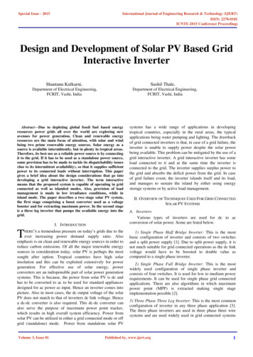
Photovoltaic (PV) CellA PV cell is a current source, not a voltage source!IoRsRpVo 0.5 VoltsVoIo 1 to 3 AmpsSimplified circuit model of a solar cellEffective use of series connected solar cells dependson identical currents being generated by each cell. 2010 Microchip Technology Incorporated. All Rights Reserved.Grid-Connected Solar Microinverter Reference Design Using the dsPIC DSCSlide 3PV cells are semiconductor devices, with electrical characteristicssimilar to a diode; however, a PV cell is a source of electricity, ratherthan an electrical load, and operates as a current source when lightenergy, such as sunlight makes contact with it.The circuit shown is an equivalent model of a PV cell.Next, we will look at more details of a PV cell and its characteristics.3
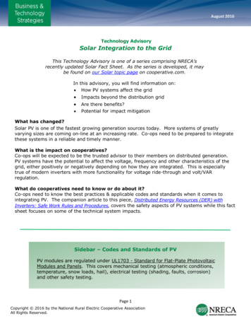
PV Cell – CharacteristicsSolar cell’s output continually varies with LIGHT and TEMPISCMaximum Power PointCurrent642ISC CurrentG 1000 W/m26G 600 W/m24G 300 W/m2VOPENMaximum Power PointG 1000 W/m210 C60 CVOPEN2Voltage1020304050I-V versus Illumination (36 cell string) 2010 Microchip Technology Incorporated. All Rights Reserved.Voltage1020304050I-V versus Temp (36 cell string)Grid-Connected Solar Microinverter Reference Design Using the dsPIC DSCSlide 4Light intensity as well as temperature affect PV cell characteristics.Current generated by a PV cell is directly proportional to light intensity.Voltage also changes with fluctuating light levels, but by much less.Voltage is more affected by changes in the temperature of the PV cellrather than the current.An increase in the cell temperature decreases the voltage andincreases the current by a very small amount.The short-circuit current (ISC) from a cell is nearly proportional to theillumination, while the open-circuit voltage (VOPEN) may drop only 10%with an 80% drop in illumination.The important result of these two effects is that the power of a PV celldecreases when light intensity decreases and/or temperature increases.4
Solar Cell – Power CurvesPowerMaximum Power Point150 WG 1000 W/m2100 WG 600 W/m250 WG 300 W/m2Voltage1020304050I-V versus Illumination(36 cell string) 2010 Microchip Technology Incorporated. All Rights Reserved.Grid-Connected Solar Microinverter Reference Design Using the dsPIC DSCSlide 5An increase in the output current after the Maximum Power Point willrapidly drop its output voltage and could produce power only 1 half ofthe open-circuit voltage and 1 half of the short-circuit current . Theusable power output could thus drop from 70% of the open-circuitvoltage times the short-circuit current (VOPEN X ISC ) to 50% or even aslittle as 25%.The amount of power generated by a PV cell depends on the operatingvoltage of the PV cell array.Its V-I and V-P characteristic curves specify a unique operating point atwhich maximum possible power is delivered.At the Maximum Power Point, the PV operates at its highest efficiency5
PV Cell ShadingString 1InverterInverterString 2Shaded Cell(s)ModuleCooler area due to previous shading 2010 Microchip Technology Incorporated. All Rights Reserved.Grid-Connected Solar Microinverter Reference Design Using the dsPIC DSCSlide 6PV manufacturer processes produce cells with relatively large variancein their power output capability.They seek to reduce their variance by using advanced manufacturingtechnology. Regardless, panel models on the market today still have 3to 5% variance in their output.Highest voltage strings or unshaded stings provide the bulk of power,and lower voltage strings due to shading or lower temperaturescontribute little power.6
Session Agenda Solar Microinverter overview Photovoltaic Cell Characteristics Solar Microinverter Configurations Grid-Connected Solar MicroinverterReference DesignSoftware IntegrationSummary 2010 Microchip Technology Incorporated. All Rights Reserved.Grid-Connected Solar Microinverter Reference Design Using the dsPIC DSCSlide 7Next, we will take a closer look at different solar inverter configurations.7
Solar Power Evolution:Grid-Connected InverterInverter 2010 Microchip Technology Incorporated. All Rights Reserved.Grid-Connected Solar Microinverter Reference Design Using the dsPIC DSCSlide 8Multiple solar modules connected in series and parallel provide 200 400 volts output and 10 to 50 Amps.Combinations of these panels are then connected to a singlecentralized inverter to yield 120/240 VAC at medium power levels (2 10KW)This system is connected to the AC power lines, hence known as GridTied system.The customer sells power to the power company during the day, andbuys power from the power company during the night.The Grid-Tied approach eliminates expensive and short lived batteries.The inverter has the potential for a single point failure and has a nonoptimal power harvest from the solar panel, especially in partial shadingconditions.In the case of multiple inverter systems – each string regardless of theoutput voltage will contribute the maximumpower it can because each inverter is optimizing the power output of itsstring. Tests indicate 20 – 34% additional energy harvest.8
Solar Power Evolution:Grid-Connected Module Incorporated Inverters terModule Incorporated Inverters (MIC) – Each solar panel module incorporatesits own inverter. An MIC is also known as a “Microinverter”.The incorporation of inverters into the solar panels greatly reduces installationlabor costs, improves safety, and maximizes the solar energy harvest. 2010 Microchip Technology Incorporated. All Rights Reserved.Grid-Connected Solar Microinverter Reference Design Using the dsPIC DSCSlide 9Here is an example of a Module Incorporated Inverter (MIC) – Eachsolar panel module incorporates its own inverter.An M-I-C inverter is also known as a “Microinverter”.The incorporation of inverters into solar panels greatly reducesinstallation labor costs, improves safety, and maximizes the solarenergy harvest.9
Objective Solar Microinverter Overview Photovoltaic Cell Characteristics Solar Microinverter Configurations Grid-Connected Solar MicroinverterReference DesignSoftware IntegrationSummary 2010 Microchip Technology Incorporated. All Rights Reserved.Grid-Connected Solar Microinverter Reference Design Using the dsPIC DSCSlide 10We can now take a closer look at Microchip’s Grid-Connected SolarMicroinverter Reference Design and its operation,starting with a high-level overview.10
Microchip’s Grid-ConnectedSolar Microinverter 220 Watt, single PV cell module (36V) microinverterMaximum Power Point Tracking 99.5%Maximum Power Point Tracking voltage 25 VDC – 45 VDCDC short circuit current: 10AAC output voltage range: 180 VAC – 264 VAC 45 Hz – 55 Hz 90 VAC – 140 VAC 55 Hz – 65 Hz Output Current THD 5%High efficiencySystem islanding 2010 Microchip Technology Incorporated. All Rights Reserved.Grid-Connected Solar Microinverter Reference Design Using the dsPIC DSCSlide 11The Grid-Connected Solar Microinverter Reference Design is available intwo versions. One version for 110V single-phase grid and one version for220V single-phase grid.Both versions are rated for a 220 Watt PV panel. The system feeds a puresine wave output current to the grid with a current Total Harmonic Distortion(THD) less than 5%.This reference design uses a dsPIC33F “GS” series digital signal controllerfor complete digital control of all power stages.Use of the reference design is Royalty Free, and complete documentation,software, and hardware design information is available on the Microchip website.Demonstration units are also available from worldwide Microchip salesoffices.11
Solar Microinverter Block DiagramSolar MicroinverterSingle PVModule36V @220WDC/DCBoostandMPPTDC/ACInverterEMI Filter 12V 5VAuxiliaryPowerSupplydsPIC SinglePhase ACGridLCDDisplayand UserInterface 3.3V 2010 Microchip Technology Incorporated. All Rights Reserved.Grid-Connected Solar Microinverter Reference Design Using the dsPIC DSCSlide 12This slide shows a system-level block diagram of the Solar Microinverter.A single dsPIC33F “GS” series digital signal controller, shown in the centerof the block diagram is used to control all of the important functions.The system is primarily divided into two sub-sections:1) DC-to-DC boost converter with Maximum Power Point Tracking and,2) DC-to-AC inverter, synchronized with the grid.12
Solar Microinverter ReferenceDesign SchematicSinglePVEMI/EMCFilterSinglePhaseAC GridModule 2010 Microchip Technology Incorporated. All Rights Reserved.Grid-Connected Solar Microinverter Reference Design Using the dsPIC DSCSlide 13A novel single-stage topology is used for this reference design. Aninterleaved active clamp Flyback inverter boosts the low-voltage DC fromthe PV panel to the high rectified AC voltage that is synchronized with thegrid voltage.The rectified AC output voltage is higher then the grid voltage.The magnitude of the Flyback inverter output varies to ensure that theinverter operates at the Maximum Power Point of the PV modulecharacteristics.13
Flyback InverterSCR FullBridgeEMI/EMCFilterGrid ConnectorBoard LayoutFeedback and ControlCircuit 2010 Microchip Technology Incorporated. All Rights Reserved.Grid-Connected Solar Microinverter Reference Design Using the dsPIC DSCSlide 14Now that we have seen a functional overview of the Solar Microinvertersystem, we can physically locate each section on a photograph of thesystem.This is a top view of the Grid-Connected Solar Microinverter ReferenceDesign.The locations of each system block are highlighted as follows:1. The dsPIC Digital Signal Controller is located at the bottom with all of itsfeedback circuitry.2. The interleaved Flyback Inverter power circuitry is located on the left sideof the board.3. The SCR full-bridge is located in the middle top area of the board4. The EMI/EMC filter is located at the top right.5. The output connector to connect to the grid is located at the top rightcorner of the board.14
Interleaved Flyback Converter Interleaved solution cancels the input current ripple,extending the capacitor life Interleaved Flyback Converter shares the input andoutput current, resulting in low copper and core lossesActive clamp reduces switching lossesRectifier diode conduction losses are reduced Interleaved solution cancels the output current ripple,resulting in lower THD 2010 Microchip Technology Incorporated. All Rights Reserved.Grid-Connected Solar Microinverter Reference Design Using the dsPIC DSCSlide 15The Interleaved Flyback Converter has the following advantages over othercommonly used topologies for solar microinverter applications. The interleaved solution cancels the input current ripple, providing a longercapacitor life The Interleaved Flyback Converter shares the input and output current,resulting in low copper and core losses The active clamp reduces switching losses The rectifier diode conduction losses are reduced The interleaved solution cancels the output current ripple resulting in lowerTotal Harmonic Distortion (THD)15
Inverter OperationFlyback ConverterVGRIDVINVPV Panel45VPVVoltageIINV25Vt 2010 Microchip Technology Incorporated. All Rights Reserved.Grid-Connected Solar Microinverter Reference Design Using the dsPIC DSCSlide 16The DC input from the PV module is fed to the Flyback primary. A modulatedhigh-frequency sine PWM is used for the Flyback MOSFETs to generate therectified sine output voltage and current across the Flyback output capacitor.The average of the sine modulated secondary diode current, produces arectified sine voltage and current across the output capacitor.The two Flyback converters are operated 180 degrees out-of-phase toaccomplish interleaved operation.16
Inverter erterGate1SinglePhaseAC GridGate2IINV/VINVIACtGate1Gate2 2010 Microchip Technology Incorporated. All Rights Reserved.Grid-Connected Solar Microinverter Reference Design Using the dsPIC DSCSlide 17The SCR full-bridge is used to convert the rectified output voltage andcurrent to sinusoidal voltage and current.Therefore, the SCR is switched at line frequency. The output of the inverteris synchronized with the grid by a Digital Phase-Locked Loop.The Maximum Power Point Tracker controls the magnitude (RMS) of theoutput current.The shape of the output current is controlled by the current control loop.17
Objective Solar Inverter Overview Photovoltaic Cell Characteristics Solar Microinverter Configurations Grid-Connected Solar MicroinverterReference DesignSoftware IntegrationSummary 2010 Microchip Technology Incorporated. All Rights Reserved.Grid-Connected Solar Microinverter Reference Design Using the dsPIC DSCSlide 18We can now take a closer look at the software implementation ofMicrochip’s Grid-Connected Solar Microinverter Reference Design.18
Flyback Solar MicroinverterSolar MPPTPWM1Single PVModule36V @ 220WPWM ModuleVDC PVEMI FilterIACVAC INVSinglePhase ACGridVAC GRIDAnalog-to-Digital ConverterDigital Control SystemDigital Signal Controller 2010 Microchip Technology Incorporated. All Rights Reserved.Grid-Connected Solar Microinverter Reference Design Using the dsPIC DSCSlide 19The dsPIC DSC device is the heart of the Solar Microinverter design andcontrols all critical operations of the system as well as the housekeepingoperations.The functions of the dsPIC DSC can be broadly classified into the followingcategories: All power conversion algorithms Inverter state machine for the different modes of operation Maximum Power Point Tracking Digital Phase-Locked Loop System islanding and Fault handling19
Control Loop – Block PV KIV/sIACS&HVAC GRIDPLLVAC INVS&HMPPTIACVPVIPVADC 2010 Microchip Technology Incorporated. All Rights Reserved.Grid-Connected Solar Microinverter Reference Design Using the dsPIC DSCSlide 20The Solar Microinverter feeds sinusoidal current to the grid; therefore, gridcurrent is being sensed for the control loop. A sine wave reference isgenerated from the sine table and is synchronized with the grid with the helpof a Digital Phase-Locked Loop.PV voltage and its output current is sensed to calculate the magnitude of thecurrent reference required for Maximum Power Point operation.A PI-type compensator is used for the control loop, and is implemented as adifference equation in software. The result of the control loop computationmodifies the duty cycle, and therefore, maintains a clean sinusoidal currentto be fed to the grid.20
Control Loop – PLLVAC GRIDOPAMP/Comparator2.5VREFZCD VAC GRIDADC BufferVAC INVS&H ADC Buffer 2010 Microchip Technology Incorporated. All Rights Reserved.Sample grid and inverter outputvoltageStored voltage polarity ( ve/-ve)Continuous check for change ingrid voltage polaritySet Zero Cross Detect (ZCD) flagif there is a change to the gridvoltage polarityGrid-Connected Solar Microinverter Reference Design Using the dsPIC DSCSlide 21In a grid-connected system, a critical component of the converter’s control isthe Phase-Locked Loop that generates the frequency and phase angle forthe reference to synchronize the output to the grid.Hardware zero-crossing detection is done with the help of a differentialamplifier and comparator.The comparator output changes its state with a change in grid voltagepolarity.Grid voltage is sampled at every ADC trigger and the polarity of the gridvoltage is stored in a register.In every sample, the grid voltage polarity has been checked. If there is achange in grid voltage polarity, the software sets the zero cross detect flag.21
Control Loop – MPPTStartSet MPPT ReferenceRead VPV, IPVPowerNew VPV * IPVYesPowerNew PowerOldMPPT ref (IAC Ref)NoPowerOldPowerNewMPPT ref(IAC REF) 2010 Microchip Technology Incorporated. All Rights Reserved.Grid-Connected Solar Microinverter Reference Design Using the dsPIC DSCSlide 22The Grid-Connected Solar Microinverter Reference Design uses the P&Omethod for Maximum Power Point Tracking.The Maximum Power Point tracker operates by periodically incrementing ordecrementing the solar array voltage. If a given agitation leads to anincrease or decrease of the output power of the PV,the subsequent agitationis generated in the same or in opposite direction.Set MPPT reference denotes the agitation of the solar array voltage, andMPPT ref andMPPT ref- represent the subsequent agitation in the same or oppositedirection, respectively.22
SoftwareGrid-Connected Solar Microinverter SoftwareUser Interface SoftwareState Machine(Interrupt-based)Priority: MediumExecution Rate: MediumPriority: LowExecution rate: LowPower Conversion Algorithm(Interrupt-based)Priority: HighExecution Rate: High 2010 Microchip Technology Incorporated. All Rights Reserved.Grid-Connected Solar Microinverter Reference Design Using the dsPIC DSCSlide 23This diagram shows the high-level partitions for the PV Inverter software.Each block represents a functional piece of software that pertains to one ofthe sub-sections of the inverter system.As seen from the diagram, software is first split into the State machine andthe User Interface Software.The State Machine software determines the mode of operation for theInverter system,detects the presence or failure of the PV module and grid , and alsoexecutes all of the power conversion algorithms.Within the state machine, the power conversion algorithms are assigned thehighest priority.The other state machine code forms the next level, or medium priority.23
General Software StructureStartInitializationEnable PeripheralsSystemState?Day Mode(NormalOperation)ErrorModeNight ModeInterrupt 2010 Microchip Technology Incorporated. All Rights Reserved.Grid-Connected Solar Microinverter Reference Design Using the dsPIC DSCSlide 24When the Solar Microinverter is turned ON, the system goes into initializationrouting and initializes all of its peripherals, variables and constants. The stateof the system will initialize with the system start-up state. The state machinefirst monitors all system variables and the input and output state. If there isno fault, the state machine switches to the system state start-up.Inside the ADC interrupt, the most recent voltage and currents are measuredand used for the control loops. The control loops are executed inside theADC interrupt routine and the PWM output is modified accordingly.This structure ensures the fastest performance, and the highest executionpriority.24
Software Block ystemError 2010 Microchip Technology Incorporated. All Rights Reserved.Grid-Connected Solar Microinverter Reference Design Using the dsPIC DSCSlide 25The Solar Microinverter State machine consists of four main operating modes:1.System Startup: the state machine will first calculate the input PV voltage and the outputgrid voltage and its frequency before setting the systemStartFlag to start the system in normaloperation.It reinitializes all of the mandatory control loop variables to ensure reliable operation during initialswitching of the PWMs.After initializing all mandatory control loop variables, the system state switches to DAY MODEoperation.2. DAY MODE: DAY MODE is the normal mode of operation. The state machine configures thesystemperipherals to execute the correct power conversion algorithms as determined by the system state.In this mode, the Solar Microinverter delivers the maximum available energy from the PV panel to thesingle-phase grid.3. NIGHT MODE: The system state switches to NIGHT MODE when there is not sufficient energyavailablefrom the connected PV panel (power 25W) or the PV panel voltage is not within the specified limit.All feedback signals are being continuously monitored and checked for fault and input/output currentcondition.4. SYSTEM ERROR: If grid voltage or input and output current is not within the specified limit,the state machine initiates system error mode. In this mode, all of the power conversion blocks areturned OFF and the input/output voltage condition and faults are monitored to recover the system inthe normal operation state if faults were removed.25
Test Result WaveformGrid Voltage and Grid Current 2010 Microchip Technology Incorporated. All Rights Reserved.Grid-Connected Solar Microinverter Reference Design Using the dsPIC DSCSlide 26The violet colored waveform is the grid voltage and the magenta coloredwaveform is the current being fed to the grid. From the captured waveformwe can see that the output current is in phase with the grid voltage.26
Test Result WaveformSystem Islanding: System Turned OFF When Grid Fails 2010 Microchip Technology Incorporated. All Rights Reserved.Grid-Connected Solar Microinverter Reference Design Using the dsPIC DSCSlide 27This waveform demonstrates islanding:From the waveform, we can see that when the grid is turned OFF nearits peak, the inverter stops feeding power to the grid.27
Test Result WaveformSystem Islanding: System Turned OFF When Grid Fails 2010 Microchip Technology Incorporated. All Rights Reserved.Grid-Connected Solar Microinverter Reference Design Using the dsPIC DSCSlide 28From this waveform, we can see that when the grid is turned OFF nearits zero crossing, the inverter stops feeding power to the grid.28
Objective Solar Microinverter Overview Photovoltaic Cell Characteristics Solar Microinverter Configurations Grid-Connected Solar MicroinverterReference DesignSoftware IntegrationSummary 2010 Microchip Technology Incorporated. All Rights Reserved.Grid-Connected Solar Microinverter Reference Design Using the dsPIC DSCSlide 29Next, lets recap what we discussed regarding Microchip’sGrid-Connected Solar Microinverter Reference Design.29
Summary Overview of Solar MicroinverterPhotovoltaic Cell CharacteristicsSolar Microinverter configurationsMicrochip Grid-Connoted SolarMicroinverter Reference SolutionHardware and Circuit OperationSoftware Architecture 2010 Microchip Technology Incorporated. All Rights Reserved.Grid-Connected Solar Microinverter Reference Design Using the dsPIC DSCSlide 30In this webinar, we discussed the photovoltaic cell characteristics,different solar microinverter configurations, and Microchip’s 220WGrid-Connected Solar Microinverter Reference Design.30
Thank You Visit www.microchip.com/smps for moredesign resourcesAvailable for Free Download: Application Note Complete Source code PCB Design files MATLAB Simulation files 2010 Microchip Technology Incorporated. All Rights Reserved.Grid-Connected Solar Microinverter Reference Design Using the dsPIC DSCSlide 31Thank you for joining me in this web seminar on Microchip’s Grid-Connected SolarMicroinverter Reference Design using the dsPIC Digital Signal Controller.Please visit the link on this page for more design details on the Grid-ConnectedSolar Microinverter as well as other Switch-Mode Power Supply Reference Designs.31
Grid-Connected Inverter Inverter Multiple solar modules connected in series and parallel provide 200 - 400 volts output and 10 to 50 Amps. Combinations of these panels are then connected to a single centralized inverter to yield 120/240 VAC at medium power levels (2 - 10KW) This system is connected to the AC power lines, hence known as Grid .