Transcription
Unit - IBASICS OF DIGITAL COMMUNICATIONOBJECTIVES To study about the basic elements or building blocks that constitutes a digitalcommunication system. To study about various types of digital communication channels.To study about the various types of signals.To study about data transmission.1.1 INTRODUCTIONThe purpose of a communication system is to transmit information-bearingsignals from a source, located at one location, to a user destination, located atanother distant location. Based on the nature of signal processing applied to theinformation-bearing signal, communication systems may be broadly divided into twomajor systems. They are:1) Analog Communication System2) Digital Communication SystemIn an analog communication system, the information bearing analog signal iscontinuously varying in both amplitude and time. It is used directly to modify somecharacteristics of a high frequency sinusoidal carrier wave, such as amplitude, phaseor frequency. Speech signal, video signal, temperature signal, pressure signal etc.,are some examples of analog signal.In digital communication system, the information bearing digital signal isprocessed such that it can be represented by a sequence of binary digits (discretemessages). Then it is used for ON/OFF keying of some characteristic of a highfrequency sinusoidal carrier wave, such as amplitude, phase or frequency. If theinput message signal is in analog form, then it is converted to digital form by theprocesses of sampling, quantizing and encoding. Computer data and telegraphsignals are some examples of digital signal.The key feature of a digitalcommunication system is that it deals with a finite set of discrete messages.Digital communication systems are becoming increasingly attractive due tothe ever-growing demand for data communication. Because digital transmissionoffers data processing options and flexibilities not available with analog transmission.Further, developments in digital techniques have led to more and more powerfulmicroprocessors, larger and larger memory devices and a number of programmablelogic devices. Availability of these devices has made the design of digitalcommunication systems highly convenient.
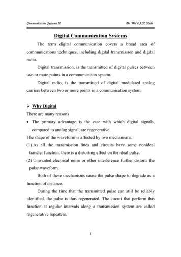
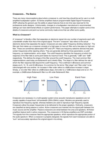
Basics of Digital Communication1.2 DIGITAL COMMUNICATION SIGNAL PROCESSINGThe transmission of information (voice, video, or data) over a path (channel)may consist of wires, waveguides, or space. The principle feature of a digitalcommunication system is that during a finite interval of time, it sends a signalwaveform from a finite set of possible waveforms. During propagation, the amplitudeand shape of the signal waveform gets degraded. The objective of the receiver is todetermine from a noise-perturbed signal which waveform from the finite set ofwaveforms was sent by the transmitter.Figure 1.1 illustrates an ideal binary digital pulse propagating along atransmission line. The shape of the waveform is affected by two basic mechanisms.1) Due to some non-ideal frequency transfer function of all transmission linesand circuits.2) Unwanted electrical noise or other interference further distorts the pulsewaveform.Both of these mechanisms cause the pulse shape to degrade as a function ofline length, as shown in the figure 1.1.Figure 1.1 Pulse degradation and regenerationDuring propagation, before the pulse is degraded to an ambiguous state,some corrective signal processing methods have to be done. This process is calledas Regeneration.In Regeneration, the pulse is amplified by a digital amplifier that recovers itsoriginal ideal shape. The pulse is thus “reborn” or regenerated. Circuits that performthis function at regular intervals along a transmission system are called Regenerativerepeaters.10
Basics of Digital Communication1.3 ADVANTAGES OF DIGITAL COMMUNICATION OVER ANALOGCOMMUNICATION1. The use of “Regenerative repeaters” generate strong error free signal at agood power level.2. Digital circuits are less subject to distortion and interference than analogcircuits.3. With digital techniques, extremely low error rates producing high signalfidelity are possible through error detection and correction.4. Digital circuits are more reliable and can be produced at a lower cost thananalog circuits.5. Digital hardware lends itself to more flexible implementation than analogcircuits.6. The combining of digital signals using Time Division Multiplexing (TDM) issimpler than the combining of analog signals using Frequency DivisionMultiplexing(FDM).7. Different types of digital signals (data, telegraph, telephone, television) canbe treated as identical signals in transmission and switching - a bit is a bit.8. Digital techniques lend themselves naturally to signal processing functionsthat protect against interference and jamming or that provide encryption andprivacy.9. Also, much data communication is from computer to computer, or from digitalinstruments or terminal to computer. Such digital terminations are naturallybest served by digital communication links.10. Storage and retrieval of voice, data or video at intermediate points (in thetransmission path) is easy and is inexpensive in terms of storage space.11. Signal processing and image-processing operations like compression ofvoice and image signals, etc. can easily be carried out.12. Adaptive equalization can be implemented.13. Very powerful encryption and decryption algorithms are available for digitaldata so as to maintain a high level of secrecy of communication.14. Availability of powerful microprocessors, larger memory devices, and numberof programmable logic devices has made the design of digital communicationsystems highly convenient.11
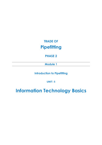
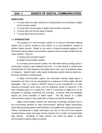
Basics of Digital Communication15. The mathematical theory of logic circuits called as switching theory is a veryuseful concept in digital communication.16. The effect of noise, temperature and parameter variations is very small indigital circuits.1.4 DISADVANTAGES OF DIGITAL COMMUNICATION OVER ANALOGCOMMUNICATION1. Digital systems tend to be very signal-processing intensive compared withanalog systems.2. Digital systems need to allocate a significant share of their resources to thetask of synchronization at various levels.3. Sometimes non-graceful degradation occurs in digital communicationsystems, ie., when the signal-to-noise ratio drops below a certain threshold,the quality of service can change suddenly from very good to very poor.4. Digital communication systems generally need more bandwidth than analogcommunication systems.5. Digital components generally consume more power as compared to analogcomponents.1.5 TYPICAL BLOCK DIAGRAM AND TRANSFORMATIONSThe principal feature of a Digital communication system is that during a finiteinterval of time, the transmitter sends a waveform from a finite set of possiblewaveforms. The receiver has to determine from a noise perturbed signal whichwaveform from the finite set of waveforms was sent by the transmitter.The block diagram of a typical digital communication system with only theessential blocks is shown in the figure 1.2(a). The functions of encryption,multiplexing, spreading, multiple access and equalization are optional.The upper blocks- Formatter, Source encoder, channel encoder, Basebandprocessor/ Band pass modulator- denote signal transformations from the source tothe transmitter. The lower blocks-Baseband decoder/Bandpass demodulator,channel decoder, source decoder, Deformatter – denote signal transformations fromthe receiver to the sink. The lower blocks essentially reverse the signal processingsteps performed by the upper blocks. We shall discuss the basic functions of eachof these blocks.12
Basics of Digital CommunicationTransmitter SectionInformationSource and inputtransducerFormatterSource encoderChannel encoderBasebandprocessor/Band ionChannel hc(t)n(t)Receiver SectionOutputSignalOutput transducerand InformationSinkDeformatterx(t)Source DecoderChannelDecoderFigure 1.2(a): Block diagram of a Typical Digital Communication System13Baseband decoder/ Band passdemodulator
Basics of Digital CommunicationTRANSMITTER SECTION1) Information sourceThe Source is where the information to be transmitted, originates.Theinformation / message may be available in digital form (eg: computer data, tele-typedata). If the information / message available is a non-electrical signal, (eg: videosignal, voice signal) then it is first converted into a suitable electrical signal using aninput transducer. Then the analog electrical signal is sampled and digitized using ananalog to digital converter to make the final source output to be in digital form.2) FormatterFormatting transforms the source information into binary digits (bits). The bitsare then grouped to form digital messages or message symbols. Each such symbol(mi, where i 1,2,3 M) can be regarded as a member of a finite alphabet setcontaining M members. Thus for M 2, the message symbol m i is binary (itconstitutes just a single bit). For M 2, such symbols are each made up of asequence of two or more bits (M-ary)3) Source encoderThe process of efficiently converting the output of either an analog or digitalsource into a sequence of binary digits is called source encoding or datacompression. Source coding produces analog-to-digital (A/D) conversion for analogsources. It also removes redundant (unneeded) information. By reducing dataredundancy, source codes can reduce a system’s data rate (ie., reduced bandwidth).Formatting and source coding are similar processes, in that they both involvedata digitization. However, source coding involves data compression in addition todigitization. Hence, a typical digital communication system would either useformatter, (for digitizing alone) or source encoder (for both digitizing andcompressing).4) Channel encoderThe channel encoder introduces some redundancy in the binary informationsequence, in a controlled manner. Such introduction of controlled redundancy canbe used at the receiver to provide error correction capability to the data beingtransmitted. This minimises the effects of noise and interference encountered in thetransmission of the signal through the channel. Hence channel coding increases thereliability of the received data and improves the fidelity of the received signal.Channel coding is used for reliable transmission of digital data.14
Basics of Digital Communication5) Base band processorFor low speed wired transmission, each symbol to be transmitted istransformed from a binary representation (voltage levels representing binary onesand zeros) to a baseband waveform. The baseband refers to a signal whosefrequency range extends from DC up to a few MHz. The baseband processor is apulse modulation circuit. When pulse modulation is applied to binary symbols, theresulting binary waveform is called Pulse Code-Modulation (PCM) waveform. Intelephone applications, the PCM waveforms are often called as Line codes. Afterpulse modulation, each message symbol takes the form of a baseband waveform,gi(t), where i 1,2 M.6) Band pass ModulatorFor transmission of high speed digital data (eg. Computer communicationsystems), the digital signal needs to be modulated. The primary purpose of thedigital modulator is to map the binary information sequence into high frequencyanalog signal waveforms (carrier signals).The term band pass is used to indicate thatthe baseband waveform gi(t) is frequency translated by a carrier wave to a frequencythat is much larger than the spectral content of gi(t). The digitally modulated signal isa band pass waveform Si(t), where i 1,2, .M. The digital modulator may simplymap the binary digit 0 into a waveform S1(t) and the binary digit 1 into a waveformS2(t). We call this as binary modulation (M 2).Alternatively, the modulator may transmit K coded information bits at a time byusing M 2K distinct waveforms Si(t), i 1,2, .M, one waveform for each of the 2Kpossible bit sequences. We call this as M-ary modulation (M 2). The band passmodulator is used for efficient transmission of digital data. The baseband processorblock is not required, if the bandpass modulator block is present. Therefore, thesetwo blocks are shown as mutually exclusive blocks.CHANNELThe communication channel is the physical medium that is used to send thesignal from the transmitter to the receiver. In wireless transmission, the channel maybe the atmosphere (free space). On the other hand, telephone channels usuallyemploy a variety of physical media, including wirelines, optical fibre cables, andwireless (microwave radio).The transmitted signal is corrupted in a random manner by a variety ofpossible mechanisms, such as additive thermal noise generated by electronic15
Basics of Digital Communicationdevices, man-made noise, eg., automobile ignition noise and atmospheric noise, eg.,electrical lightning discharges during thunderstorms.As the transmitted signal Si(t) propagates over the channel, it is impacted bythe channel characteristics, which can be described in terms of the channel’simpulse response hc(t). Also, at various points along the signal route, additiverandom noise n(t) distorts the signal. Hence the received signal x(t) must be termedas the corrupted version of the transmitted signal Si(t). The received signal x(t) canbe expressed asx(t) Si(t) hc(t) n(t)i 1,2 .Mwhere * represents a convolution operation and n(t) represents a noise process.RECEIVER SECTION1. Baseband decoderThe baseband decoder block converts back the line coded pulse waveform totransmitted data sequence.2. Band pass demodulatorThe receiver front end and/or the demodulator provides frequency downconversion for each of the received band pass waveform x(t). Digital demodulationis defined as recovery of a waveform (base band pulse). The demodulator restoresx(t) to an optimally shaped baseband pulse z(t) in preparation for detection.Detection is defined as decision-making regarding the digital meaning of thatwaveform.Typically there are several filters associated with the receiver anddemodulator(i)Filtering to remove unwanted high frequency terms (in the Frequencydown conversion of band pass waveforms.)(ii)Filtering for pulse shaping.(iii)Filtering option by equalisation to reverse any degrading effects on thesignal caused by the poor impulse response of the channel.Finally the detector transforms the shaped pulse to an estimate of thetransmitted data symbols (binary or M-ary).Demodulator is typically accomplished with the aid of reference waveforms.When the reference used is a measure of the entire signal attributes (particularlyphase), the process is termed coherent. When phase information is not used, theprocess is termed non-coherent.16
Basics of Digital Communication3. Channel decoderThe estimates of the transmitted data symbols are passed to the channeldecoder. The channel decoder attempts to reconstruct the original informationsequence from knowledge of the code used by the channel encoder and theredundancy contained in the received data. A measure of how well the demodulatorand decoder perform is the frequency with which errors occur in the decodedsequence. This is the important measure of system performance called asProbability of bit error (Pe).4. Source decoderThe source decoder accepts the output sequence from the channel decoder.From the knowledge of the source encoding method used, it attempts to reconstructthe original signal from the source. Because of channel decoding errors and possibledistortion introduced by the source decoder, the signal at the output of the sourcedecoder is an approximation to the original source output. The difference of thisestimate and the original digital signal is the distortion introduced by the digitalcommunication system.5. DeformatterIf the original information source was not in digital data form and the output ofthe receiver needs to be in the original form of information, a deformatter block isneeded. It converts back the digital data to either discrete form (like keyboardcharacters) or analog form (speech signal).6. Information sinkIf an analog output is needed in non-electrical form, the output transducerconverts the estimate of digital signal to the required analog output. The informationsink may be computer, data terminal equipment or an user.7. SynchronizationSynchronization and its key element, a clock signal, is involved in the controlof all signal processing within the digital communication system. It actually plays arole in regulating the operation of almost every block. Synchronization involves theestimation of both time and frequency. Coherent systems need to synchronize theirfrequency reference with the carrier in both frequency and Phase. For non-coherentsystems, phase synchronization is not needed.17
Basics of Digital CommunicationBASIC DIGITAL COMMUNICATION TRANSFORMATIONSThe basic signal processing functions which maytransformations can be classified into the following nine groups.beviewedas1. Formatting and Source Coding:Formatting and source coding are similar processes, in that they both involvedata digitization.digitization.Source coding also involves data compression in addition to2. Baseband SignalingBaseband signaling process involves generation of PCM waveforms or linecodes.3. Bandpass signalingDuring demodulation, when the references used are a measure of all thesignal attributes (particularly phase), the process is termed coherent. When phaseinformation is not used, the process is termed non coherent.4. EqualizationAn equalization filter is needed for those systems where channel induced ISI(Intersymbol interference) can distort the signals.5. Channel CodingWaveform coding and structured sequences are the two methods of channelcoding. Waveform coding involves the use of new waveforms. Structuredsequences involve the use of redundant bits.6. Multiplexing and multiple accessMultiplexing and multiple access both involve the idea of resource sharing.Multiplexing takes place locally and multiple access takes place remotely.7. SpreadingSpreading is used in military applications for achieving interference protectionand privacy. Signals can be spread in frequency, in time, or in both frequency andtime.8. EncryptionEncryption and decryption are the basic goals, which are communicationprivacy and authentication. Maintaining privacy means preventing unauthorizedpersons from extracting information (eavesdropping) from the channel. Establishing18
Basics of Digital Communicationauthentication means preventing unauthorized persons from injecting spurioussignals (spoofing) into the channel.9. SynchronizationSynchronization involves the estimation of both time and frequency. Coherentsystems need to synchronize their frequency reference with the carrier in bothfrequency and phase. For non coherent systems, phase synchronization is notneeded.The figure 1.2(b) shows the basic digital communication transformations.Fig. 1.2(b) Basic digital communication transformationsPerformance criteriaA digital communication system transmits signals that represent digits. Thesedigits form a finite set or alphabet, and the set is known a priori to the receiver. Afigure of merit for digital communication systems is the probability of incorrectlydetecting a digit or the probability of error (Pe).1.6 CHANNELS FOR DIGITAL COMMUNICATIONThe transmission of information across a communication network isaccomplished in the physical layer by means of a communication channel. Onecommon problem in signal transmission through any channel is additive noise.19
Basics of Digital Communication1.8 INFORMATION CAPACITYThe information capacity is defined as the maximum rate at which informationcan be transmitted across the channel without error. It is measured in bits persecond.A key issue in evaluating the performance of a digital communication systemis that the maximum rate at which reliable communication can take place over thechannel.1.9 SHANNON’S LIMIT FOR INFORMATION CAPACITYShannon-Hartley capacity theorem:The Shannon’s channel capacity theorem defines the fundamental limit on therate of error free transmission for a power-limited, band-limited Gaussian Channel.The information capacity C of a channel perturbed by additive white Gaussian Noise(AWGN) is a function of the average received signal power S, the average noisepower N, and the bandwidth B. The information capacity relationship (ShannonHartley theorem) can be stated as𝑆C B log 2 ( 1 𝑁) , bits/s(1.13)We can rewrite the noise power as N NoB, where No is the noise powerspectral density. Hence, the theorem can be written asC B log 2 ( 1 𝑆𝑁𝑜 𝐵) , bits/s(1.14)The significance of the channel capacity is as follows:(i)If the information rate R from the source is less than or equal tochannel capacity C (R C), then it is possible to achieve reliable(error-free) transmission through the channel by appropriate coding.(ii)If the information rate R from the source is greater than the channelcapacity C (R C), it is not possible to find a code that can achievereliable (error-free) transmission through the channel.Thus, Shannon established basic limits on communication of information andgave birth to a new field that is now called Information Theory.26
Basics of Digital CommunicationExample problem 1.1: Calculate the capacity of a standard 4kHz telephonechannel with a 32dB signal-to-noise ratio.Solution:The standard telephone channels occupy the frequency range of 300Hz to3400Hz. Hence, the bandwidth is B 3400-300 3100HZSignal-to-noise ratio (S/N) in decibels 𝑆Hence, 10 log10 ( ) 𝑁𝑆 32log10 (𝑁) 𝑆anti log(3.2) 𝑁 10Therefore,𝑆𝑁Capacity of a channel, C32dB323.21584.89 1585 B.log 2 (1 𝑁)𝑆𝑆On substituting the values of B and𝑁, we haveC capacity,C 3100 x log 2 (1 1585) 3100 x log 2 (1586) 3100 x 3100 x 10.63 32953 bits per secondlog10 1586log10 23.2003 3100 x 0.3010 32953Exercise Problem 1.8.1: A system has bandwidth of 4kHz and a signal-tonoise ratio of 28dB at the input to the receiver. Calculate its informationcarrying capacity.1.10DATA TRANSMISSIONThe data transmission involves the transmission of information such asdigitized voice, digitized image and video, computer generated data, and so on. Fordata transmission and reception, a data network is established. A data network is a27
Formatting and Baseband ModulationFormatting transforms the source information into bits, thus assuringcompatibility between the information and the signal processing steps within thedigital communication system. The information remains in the form of a bit streamupto the pulse modulation block.Information sources can be analog or discrete.Hence, the output of aninformation source may be digital information, textual information or an analoginformation. Data already in a digital format would bypass the formatting function.Textual information is transformed into binary digits by the use of coder. If the datais in the form of alphanumeric text, then it will be character encoded with one ofseveral standard formats such as ASCII, EBCDIC, Baudot, and Hollerith.Analog information is formatted using three separate processes: Sampling,quantization and coding. For all types of information sources, the formatting stepresults in a sequence of binary digits.The pulse modulator converts the bit stream into a sequence of pulsewaveforms. The characteristics of this sequence of pulses correspond to the digitsbeing sent. These pulse waveforms are then transmitted through a basebandchannel, such as pair of wires or a coaxial cable.After transmission through the channel, the pulse waveforms, are recovered(demodulated) and detected to produce an estimate of the transmitted digits. Thefinal step is the reverse formatting, which recovers an estimate of the sourceinformation.2.3 FORMATTING ANALOG INFORMATIONAnalog information sources can be transformed into digital sources throughthe use of sampling and quantization. We utilize sampling to convert a continuoustime signal to a discrete time signal, process the discrete-time signal using a discretetime system and then convert back to continuous-time signals.2.3.1 The Sampling theoremSampling of the signals is the fundamental operation in signal-processing. Acontinuous-time signal is first converted to discrete-time signal by sampling process.Sampling theorem gives the complete idea about the sampling of signals. Theoutput of the sampling process is called pulse amplitude modulation (PAM).Because the successive output intervals can be described as a sequence of pulseswith amplitudes derived from the input waveform samples. The analog waveformcan be approximately retrieved from a PAM waveform by simple low-pass filtering.41
Formatting and Baseband ModulationThe statement of sampling theorem can be given in two parts as below:(i) A band limited signal of finite energy, which has no frequencycomponents higher than fm Hertz, is completely described by its sample1values at uniform intervals less than or equal to 2𝑓 seconds apart.𝑚(ii) A band limited signal of finite energy, which has no frequencycomponents higher than fm Hertz, may be completely recovered fromthe knowledge of its samples taken at the rate of 2f m samples persecond.Combining the two parts, the uniform sampling theorem may be stated asfollows:“A continuous-time signal may be completely represented in its samples andrecovered back if the sampling frequency is fs 2fm”.Here fs is the sampling frequency and fm is the maximum frequency present inthe signal.2.3.2 Nyquist theoremThe Nyquist theorem provides a prescription for the nominal sampling intervalrequired to avoid aliasing. It may be stated as follows:“The sampling frequency (fs) must be at the rate equal to or greater than twicethe highest frequency component (fm) present in the signal ie.,fs 2fm , in order torecover the signal exactly.”(i)When the sampling rate becomes exactly equal to 2fm samples persecond, then it is called as Nyquist rate. Nyquist rate is also defined asthe minimum sampling rate. It is given byfs(ii) 2fm(2.1)Similarly, maximum sampling interval is called as Nyquist interval. It isgiven byNyquist interval, Ts where,(iii)fs 12𝑓𝑚seconds,(2.2)1𝑇𝑠The restriction of fs 2fm, stated in terms of the sampling rate, is known asthe Nyquist criterion. The Nyquist criterion is a theoretically sufficientcondition to allow an analog signal to be reconstructed completely from aset of uniformly spaced discrete time samples.42
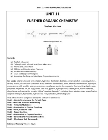
Formatting and Baseband Modulation2.4 SAMPLING TECHNIQUESThe sampling of a continuous-time signal is done in several ways. Basically,there are three types of sampling techniques. They are:1. Impulse sampling2. Natural sampling3. Flat top sampling (Sample and hold operation)2.4.1 Impulse sampling or Ideal samplingIf the sampling function is a train of impulses, then the method is calledImpulse sampling or Ideal sampling. Figure 2.2(c) shows this sampling function.Figure 2.2(g) shows a circuit to produce this sampling. This circuit is known as theswitching sampler.X(t)fs(g)Figure 2.2 Impulse Sampling43Xs(t)
Formatting and Baseband Modulation1Let us choose Ts 2𝑓 , so that the Nyquist criterion is just satisfied. The circuit𝑚simply consists of a switch. If we assume that the closing time ‘t’ of the switchapproaches zero, then the output xs(t) will contain only instantaneous value of theinput signal x(t). This instantaneous sampling gives a train of impulses of heightequal to the instantaneous value of the input signal x(t) at the sampling instant.The train of impulses (sampling function) may be represented asx (t) 𝑛 (𝑡 𝑛𝑇𝑠 )(2.3)Where Ts is the sampling period and (t) is the unit impulse or Dirac deltafunction. The sampled signal xs(t) is expressed as the multiplication of x(t) and x (t).Thus, xs(t) x(t).x (t)(2.4)xs(t) x(t). 𝑛 (𝑡 𝑛𝑇𝑠 )(2.5) 𝑛 𝑥(𝑛𝑇𝑠 ). (𝑡 𝑛𝑇𝑠 )(2.6) xs(t) Demerits of Impulse sampling:Impulse sampling results in the samples whose width T approaches zero.Due to this, the power content in the instantaneously sampled pulse is negligible.Thus, this method is not suitable for transmission purpose.Spectrum:The spectrum X (f) of the sampled signal xs(t) is shown in the figure 2.2(f) forfs 2fm. Using the frequency convolution property of the Fourier transform, we cantransform the time domain product x(t).x (t) of equation(2.6) to the frequency domainconvolution X(f)*X (f).Therefore,Xs(f) X(f) X (f) X(f) [ 𝑇 𝑛 (𝑓 𝑛𝑓𝑠 )] Xs(f) 1𝑠1𝑇𝑠 𝑛 𝑋(𝑓 𝑛𝑓𝑠 )(2.7)(i) From the figure, we infer that, if the sampling rate is chosen such thatfs 2fm, then each spectral replicate is separated from each of its neighbours by afrequency band exactly equal to fs Hertz. Therefore, the analog waveform cantheoretically be completely recovered from the samples, by the use of filtering.44
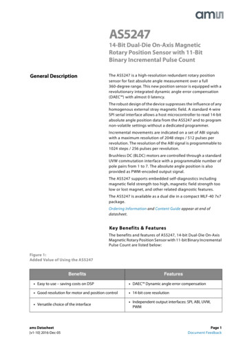
Formatting and Baseband Modulation(ii) If the sampling rate is chosen such that fs 2fm, the spectral replications willmove farther apart in frequency, as shown in Figure 2.3(a),Figure 2.3 Spectra for various sampling ratesNow, it is easier to perform the filtering operation. A typical low-pass filtercharacteristic that might be used to separate the baseband spectrum from those athigher frequencies is also shown in the figure.(iii) When the sampling rate is reduced, such that f s 2fm, the spectralreplications will overlap, as shown in the figure 2.3(b). Therefore, some informationwill be lost. This phenomenon is called “aliasing” which results from under sampling(sampling at too low a rate).Conclusion The Nyquist rate, fs 2fm is the sampling rate below which aliasing occurs. To avoid aliasing, the Nyquist criterion, fs 2fm must be satisfied.2.4.2 Natural SamplingNatural sampling is a practical method. Here the sampling function is a pulsetrain or switching waveform xp(t). Figure 2.4(c) shows this sampling function. Figure2.4(g) shows a functional diagram of a natural sampler.45
Formatting and Baseband ModulationXp(t)X(t)Xs(t)(g)Figure
information-bearing signal, communication systems may be broadly divided into two major systems. They are: 1) Analog Communication System 2) Digital Communication System In an analog communication system, the information bearing analog signal is continuously varying in bo