Transcription
The power behind competitivenessGrid-tie Transformerless Solar InverterH8E / H9E / H10EOperation and Installation Manualwww.deltaww.com
Contents12345General Information.61.1Scope of delivery . 61.2General Warnings / Notes on Safety . 61.3Validity. 71.4Product Description . 71.5How it Works . 71.6Additional Information. 7Package Inspection.82.1Unpacking . 82.2Package Inspection. 82.3Identification Label . 10Product Overview . 113.1Dimensions. 113.2Function Introduction . 113.3LED Indicator . 123.3.1Introduction . 123.3.2LED Status . 123.3.3LED Message . 133.4Reset Button. 14Installation . 154.1Instruction . 154.2Installation Location . 154.3Mounting. 15Wiring . 195.1Preparation before Wiring . 195.2Opening the wiring box cover . 205.3AC Grid Connection : L N PE . 215.3.1AC circuit breaker requirements . 215.3.2AC Connection . 215.4DC Connection (from PV Array). 225.4.1DC connector of H8E / H9E / H10E . 235.4.2DC cable connection . 235.5Grounding . 243
5.6Power meter . 246 Turning the PV inverter on/off . 266.1Start-up Procedures . 266.1.1PV Array DC Voltage Checking . 266.1.2AC Utility Voltage Checking . 266.1.3Starting up the Inverter . 266.1.4Wi-Fi communication. 266.2Shut down Procedures . 277 Active/Reactive Power Control . 287.1Active Power Control . 287.1.1Power vs. Voltage. 287.1.2Power vs. Frequency . 287.2Reactive Power Control . 297.2.1Fixed Power Factor mode . 297.2.2Fixed Reactive Power mode. 297.2.3cosφ - P mode . 297.2.4Voltage – var response mode . 307.3Demand Response Mode . 308 Maintenance . 329 Error Message and Trouble Shooting . 339.1Error Message & Trouble Shooting . 3310 De-Commissioning . 4211 Technical Data. 43FigureFigure 1-1: Solar system operation illustration .7Figure 2-1 : Unpacking process .8Figure 2-2: Components of H8E / H9E / H10E .9Figure 2-3: Components of Power meter .9Figure 2-4: The identification label .10Figure 3-1: Dimensions of H8E / H9E / H10E.11Figure 3-2 : Inverter exterior objects .12Figure 3-3 : Reset button .14Figure 4-1 : Attaching the mounting bracket for H8E / H9E / H10E.164
Figure 4-2 : Correct and incorrect installation illustration .17Figure 4-3 : Adequate installation gap .18Figure 5-1: Connection of a system for floating solar array .19Figure 5-2: Removing the wiring box cover.20Figure 5-3: Locations of wiring box conduit plugs .20Figure 5-4: AC cable connection.22Figure 5-5: DC cable connection .23Figure 5-6: Ground cable connection .24Figure 5-7: Power meter wiring .25Figure 7-1: Power vs. Voltage (example for Australia) .28Figure 7-2: Power vs. frequency characteristic .29Figure 7-3: Example of cosφ – P characteristic.30Figure 7-4: Example of Voltage - var characteristic (Australia) .30Figure 7-5: DRM mode diagram .31TableTableTableTableTableTableTableTable2-1: Packing list of H8E / H9E / H10E and Power meter .93-1: LED indicator.123-2: LED Message .133-3: Reset button function .145-1: Recommended upstream protection .219-1: Error Message .4111-1: Specifications .445
1 General Information1.1Scope of deliveryCongratulations on the purchase of your Delta H8E / H9E / H10E grid-tied solar inverter.This manual will assist you in becoming familiar with this product. Please observe allsafety regulations and take into account the connection requirements by your local gridutility.1.2General Warnings / Notes on SafetyCareful handling of the product will contribute to it's service life durability and reliability.Both are essential to ensure maximum yield from your product. As some of the solarinverter models are heavy, two people may be required for lifting purposes.CAUTION !During operation of electrical devices, certain parts are under dangerous voltage.Inappropriate handling can lead to physical injury and material damage.Always adhere to the installation regulations. Installation may only be conductedby certified electricians.WARNING !Repair work on the device should ONLY be carried out by the manufacturer.The inverter contains no user serviceable parts inside.Please observe all points in the operation and installation manual. Isolate the devicefrom the grid and the PV modules before undertaking work on the device.DANGER!To avoid risk of electrical shock, do not open the solar inverter. The inverter containsno user-serviceable parts. Opening the inverter will void the warranty.Dangerous voltage is present for 1 minute after disconnecting all sources ofpower, recommend 5 minutes for discharging.Remember that the unit has a high leakage current. The PE conductorMUST be connected prior to commencing operation.WARNING !The internal temperature may exceed over 70 C while operating.To avoid injury, do not touch the surface of the inverter whilst the unit is inoperation.ATTENTIONFor operation and installation of inverter refer to the user manual.Failure to comply with the instructions in this manual may void the warranty.6
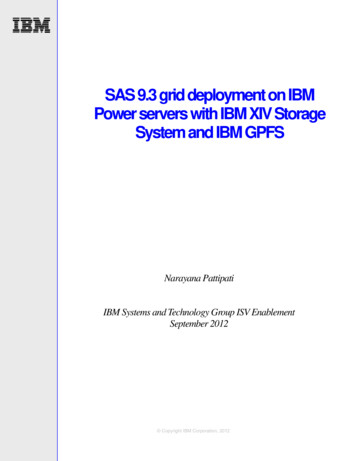
1.3ValidityThis user manual describes the installation process, maintenance, technical data andsafety instructions of the following solar inverter models under the DELTA brand. H8E1.4 H9E H10EProduct DescriptionThis device is a single-phase grid-tie solar inverter. It converts direct current (DC)electricity from the PV array into single phase alternating current (AC) to supply powerto the load and feed the excess generated power back to the local grid. This inverterallows for a wide voltage input range and has a high performance efficiency and userfriendly operation. In addition, the special DSP(Digital Signal Processor) design reduces the complexity of the circuit and electroniccomponents. Please note that this device does not support off-grid function. The featuresfor H8E / H9E / H10E are shown below.Features Max Output Power Rating: 8kVA (H8E), 9kVA (H9E), 10kVA (H10E) Single–phase (L N PE), Grid-tie, transformerless solar inverter Maximum efficiency : 98.0% Europe efficiency : 97.3% Reactive power capability (Cap 0.85 – Ind 0.85) Total harmonic distortion (THD 3%) @ full load1.5How it WorksThe operation of a solar inverter is shown in Figure 1-1.In order to save energy and electricity, the solar inverter converts the DC input powersupplied from the PV Array into single-phase AC output power to Grid.PV ArraySolar InverterElectrical GridFigure 1-1: Solar system operation illustration1.6Additional InformationFor more detailed information for H8E / H9E / H10E or other related product information,please visit : www.deltaww.com7
2 Package Inspection2.1UnpackingUnpacking process is shown as Figure 2-1.Figure 2-1 : Unpacking processUpon receiving your brand new inverter, you will be required to remove it’s protectivepackaging. This packaging consists of various materials that will need to be disposed ofaccording to the specific recycling marking printed on them.2.2Package InspectionUnforeseeable events causing damage or movement may occur during shipment.Please check for damage on the packaging upon receiving your inverter. Please checkthe model number and the serial number on the packaging is identical with the modelnumber and serial number on the unit itself.Check if all the accessories are in the package, the standard accessories are listed asTable 2-1.8
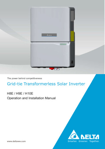
Figure 2-2: Components of H8E / H9E / H10EPower meter is necessary function for H8E / H9E / H10E to meet the requirements ofAS4777. The length of current sensor cable is available at 10m or 30m.5 6 Figure 2-3: Components of Power meterH8E / H9E / H10EObjectQtyDescription① PV Inverter1Solar inverter② Quick installation guide1Important safety instructions and technical specificationsshould be followed during installation.3 Wall-Mount Bracket1To mount the solar inverter securely on the wall.4 Antenna1For communication5 Current Sensor1Current Sensor for power meter function6 Current Sensor Cable1Cable for current sensor, length of 10m or 30mTable 2-1: Packing list of H8E / H9E / H10E and Power meter9
CAUTION !If there is any visible damage to the inverter/accesories or any damage to thepackaging, please contact your inverter supplier before installation.2.3Identification LabelUsers can identify the model name by the information on the product label. The modelname, serial number and other specifications can be located on the product label. Forlabel location, please refer to Figure 2-4.Figure 2-4: The identification label (H10E)10
3 Product Overview3.1DimensionsUnit: mmFigure 3-1: Dimensions of H8E / H9E / H10E3.2Function IntroductionThe Inverter’s exterior is shown in Figure 3-2.11
Product LabelWarning LabelLED IndicatorConduit hole for DCLockable DC SwitchConduit hole for comm.Reset ButtonHole for AntennaConduit hole for ACFigure 3-2 : Inverter exterior objects3.33.3.1LED IndicatorIntroductionThere are five LEDs in the front side of the inverter, from left to right, it is used forindicating status of operation, battery, communication, information and fault.Note: Battery LED is a reserved design for energy storage inverter. The status of thisLED is meaningless for H8E / H9E / H10E.3.3.2LED StatusLabel DesignationColorOperation(OPER)Red / GreenBattery(BAT)Red / GreenWireless Communication(COMM)Red / GreenInformation(INFO)Red / GreenFault(FAULT)Red / GreenTable 3-1: LED indicator12
3.3.3LED MessageThe LEDs indicate the operational status of the inverter.MessageCategoryOPER LedLED SignalsLEDColor StatusNormaloperationSync.OPER Green ON OPER Green BAR Message ExplanationExampleBehaviorConstant on The inverter feeds ingrid.Four LEDsThe inverter isform asynchronizing with grid.progressbar.LED signals:OPER LED is ON,BATGreen BAR COMM Green BAR BAT LED is ON.INFOBlinks Message:COMM LEDGreen BAR Synchronizationprogress is 50%75%.Night modeBAT Led :OPER Green BLINK 1s on, 4s off Grid is connected, butthe inverter is unable tofeed in grid because PVvoltage is too low.Meaningless for H8E / H9E / H10ECOMM LedBLE failAPPConnectedBLEisrunningINFO LedCOMM Red ON COMM Green ON onstant on BLE is in fault modeConstant on APP is connectedCOMM Green BLINK 1s on, 1s off BLE is runningINFOINFOYellow BLINK 1s on, 1s off Firmware upgrading isongoingGreen BLINK 1s on, 1s off Inverter is receivingimage fileYellow ON Constant on External event occursand inverter is unable torunFAULT LedGround fault FAULT RedOtherInitialization BLINK 1s on, 1s off Ground fault occursOPER Green ON BATGreen ON COMM Green ON INFOGreen ON On untildoneOn untildoneOn untildoneOn untildoneInverter initializationwhen grid is changingfrom disconnected intoconnected.Table 3-2: LED Message13Only BLINK for 2cycles in one minute
3.4Reset ButtonThere is button located inside the junction box, for this button, there are followingfunctions.OperationFunctionsPush 3s 10sReset Wi-Fi modulePush 10s 20sClear AFCI FaultPush 20s Reset Wi-Fi module, and Wi-Fi password returns tothe default: DELTASOLTable 3-3: Reset button functionReset ButtonFigure 3-3 : Reset button14
4 Installation4.1InstructionDue to the variety of users and installation environments, you must read this manualthoroughly before installation. Installation of the unit and start-up procedures must becarried out by an accredited technician.4.2Installation LocationThe inverter can be installed in indoors / outdoors.WARNING !Do not install the unit near or on flammable surfaces. Mountthe unit tightly on a solid/smooth surface.CAUTION !The unit should not be installed in direct sunlight.4.3MountingThis unit is designed to be wall-mounted. Please ensure the installation is perpendicularto the floor and the AC plug located at the base of the unit. Do not install the device ona slanting wall. The dimensions of the mounting bracket are shown in the figure below.To mount the inverter on the wall, please follow the procedure below:1)2)3)Screw the mounting bracket on the wall with 4 * Φ6 mm Phillips head screws.Attach the inverter to the mounting bracket.Use Hex Wrench fixing the inverter with 2 * Φ6.0mm Hexagon Socket screw.Please refer to Figure 4-1 and Figure 4-2.15
123Figure 4-1 : Attaching the mounting bracket for H8E / H9E / H10E16
Inverter must be installed vertically with a maximum incline of /-5 on a flat surfaceFigure 4-2 : Correct and incorrect installation illustrationCAUTION ! The bracket supplied with the unit is specially designed and should be the onlymounting device used for the unit. It is recommended to install the inverter in a suitable location which offers easyand safe access for service and maintenance. Please leave an appropriate gap in between units when installing multiple solarinverter systems. Please install solar inverter at eye level to allow easy observation for operationand parameter setting. Ambient temperature for operation: -25 C 65 C (power derating above 45 C).Please ensure the spacing requirement to allow for sufficient convective cooling.It is essential to ensure sufficient space for product operation as shown in Figure 4-3.17
Figure 4-3 : Adequate installation gap18
Wiring5 Wiring5.1Preparation before Wiring1)2)3)4)5)Ensure voltage values and polarities are correct.When grounding the solar array positive or negative terminal, an isolationtransformer is required due to the H8E / H9E / H10E not havinggalvanicisolation between the DC-input and AC-output.The ground fault detection is a fixed internal setting. It cannot be modified.Please refer to Figure 5-1 for connections. Inverter can accept DC inputs inparallel.According to IEC 62109-2, the PV modules need to have an IEC 61730 ClassA rating.Figure 5-1: Connection of a system for floating solar arrayWARNING! SHOCK HAZARDWhen the photovoltaic array is exposed to light, it supplies a DC voltage to theInverter, a shock hazard may exist due to output wires or exposed terminals.To reduce the risk of shock during installation, cover the array with an opaque(dark) material and ensure that the Disconnect Device in the inverter is set toOFF before commencing any wiring.19
5.2Opening the wiring box cover1)2)3)Place DC Disconnect switch in “OFF” position. Please note the cover cannotbe removed when the DC Disconnect switch is in the “ON” position.Remove the 4 cover screws indicated above with a T20 Torx screw driverLift the cover upward and place off to the side.Figure 5-2: Removing the wiring box coverFigure 5-3: Locations of wiring box conduit plugs20
WiringConduit plugs are provided for 1in, 3/4 inch and ½ inch conduit fittings. If conduit fittingnot fit 1in, 3/4in or 1/2in, an appropriate conduit reducer or adapter should be used.Caution: Do not enlarge the wiring compartment conduit openings as the wiring boxenclosure will be damaged which will void the inverter warranty.5.3AC Grid Connection : L N PEWARNING !Before commencing AC wiring, please ensure all AC circuit breakers are switched off.5.3.1AC circuit breaker requirementsPower ratingUpstream AC circuit breakerH8E8 kVA40 AH9E9 kVA50 AH10E10 kVA50 ATable 5-1: Recommended upstream protection5.3.2AC ConnectionThe AC compatible wiring gauge is 8(8mm 2)-10(6mm 2)AWG, should have anampacity based on AS/NZS 4777.1, and it is recommended to use 90 C(194 F) copperwires. Please check local requirements if there are any additional requirements.When calculating the cross section of the cable, consider: material used thermal conditions cable length type of installation AC voltage drop power losses in cableAlways follow the system installation requirements defined for your country!Connection AC cables according to following:1) Route AC wire through the conduit and strip the wire end to 0.7 inches.2) Use 3/16 inch flat blade screw driver to push the spring of each terminal.3) Connect the wires (L, N) to the connectors according to the marks. Connectthe wire (GND) to the grounding terminal (Please see detail in “Grounding”section).Note: Verify the connection is correct.21
Figure 5-4: AC cable connection5.4DC Connection (from PV Array)WARNING ! When undertaking DC wiring, please ensure the correct polarities are connected. When undertaking DC wiring, please ensure that the DC isolator switch on thePV array is OFF.CAUTION !The maximum open circuit voltage of the PV Array must not exceed 600Vdc.NOTEThe isolator installed between the PV Array and inverter must meet the rating ofvoltage higher than this device’s maximum input voltage.22
Wiring5.4.1DC connector of H8E / H9E / H10EThe inverters operate using 4 separate MPP trackers that can handle both symmetricaland asymmetrical loads to allow for optimum adjustment. This allows for therequirements of complex PV system designs to be fulfilled.5.4.2DC cable connectionThe DC compatible wiring gauge is 10(6mm 2)-12(4mm 2)AWG, should have anampacity based on AS/NZS 4777.1, it is recommended to use 90 C(194 F)Connection DC cables according to following:1)2)3)Route the PV wires through the conduit, and strip the wire end to 0.5 inches.Use 3/16 inch flat blade screw driver to push the spring of each terminal.Connect the positive wires to PV terminals and connect the negative wiresto PV- terminals .Note: Verify the connection before power up the inverter.Figure 5-5: DC cable connection23
5.5GroundingSix Grounding Electrode Conductors are installed inside the wiring box, They are torxhead screw type connectors.The terminals accept solid or stranded copper 10(6mm 2)4(22mm 2) AWG wire, recommend screw torque is 18 in-lbs (2Nm).Figure 5-6: Ground cable connectionWARNING !As the leakage current is too large,an additional grounding point isprovided in the wiring box as below. The additional grounding point mustbe reliable grounding. The minimum size of the additional grounding wireis 10(6mm2)AWG.5.6Power meterConnecting the current sensor in the following steps:(1) Attach a current sensor to the L cables of the main earth leakage circuitbreaker, Clamp the current sensor and make sure that the direction is correct.(2) Connect one end of the current sensor cable to the current sensor connectionterminal and the other end to the Meter terminal in the junction box of inverter.24
WiringTo Electrical GridN LStep eterStep (2)DRM1/5Step (2)Local LoadFigure 5-7: Power meter wiring25
6 Turning the PV inverter on/offWARNING !The internal temperature may exceed over 70 C while operating. Toavoid injury, do not touch the surface of the inverter whilst the unit is inoperation.After installation, please ensure the AC, the DC and communicationconnection are correct. When enough power is generated from the PVarray, the device will operate automatically and will initial ‘self-test’. Thisself-test takes approximately 2 minutes and will occur at first start-up ofthe day.6.1Start-up Procedures6.1.1PV Array DC Voltage CheckingFirstly, uncover the PV arrays and expose them to full sunlight. Please note, the sunlightmust be intense enough to produce the required output voltage for the inverter to startup.Measure the PV array open circuit DC voltage across the DC positive ( ) and negative(-) terminals.6.1.2AC Utility Voltage CheckingUsing an AC voltmeter, measure the AC open circuit utility voltage between L1 (L) andL2 (N) Ensure the voltage is at approximately the nominal value. The inverter operateswith a line-to-line voltage range around the nominal value.Refer to “11. Technical data” output section for the utility voltage operating range for yourinverter model.6.1.31)2)3)4)Starting up the InverterSwitch on the PV Array switch and DC switch to connect PV Array.Switch on AC circuit breaker to connect electricity grid.Communication ModuleUpon first start-up of the inverter, countryselection is required, pleasecontact yoursystem installer to process the setting.More informationplease refer to "Get Started Register" guide.The Communication Module supports the communication with the device with Wi-Fifunction (e.g., smart phone, tablet ect.)6.1.41)Wi-Fi communicationTurn on the device’s Wi-Fi function.26
Wiring2)3)4)Select the inverters' Wi-Fi SSID: Delta-[serial number](e.g. Delta-O4L16A00001W0 ; See Inverter ” The identification label”)Enter the Wi-Fi password: DELTASOL(The Default password is also printed on the identification label)Use the "MyDeltaSolar" APP (You can download the APP via googleplay or App Store)Please note:1)2)6.2The product only support one device communicating at the sametime.If the Wi-Fi password is forgotten, press and hold the Reset Buttonmore than 20s to return the Default password to (”DELTASOL”).Shut down Procedures1)2)Switch off AC circuit breaker to disconnect electricity grid.Switch off the PV Array switch and DC switch to disconnect PV Array.CAUTION !Due to the variety of installation environments, installation of the unit and start-upprocedures must be carried out by an accredited technician.Incorrect settings may cause the inverter to malfunction27
7 Active/Reactive Power ControlThere are 2 settings for active power and 4 settings for reactive power control that canbe configured based on the requirement of the local network operator.ATTENTIONThe parameters are set according to the requirements of the selected country.A change to the parameter settings may result in the approval being lost.7.17.1.1Active Power ControlPower vs. VoltageAccording to AS/NZS 4777.2:2015 (6.3.2):The volt–watt response mode varies the output power of the inverter in response to thevoltage at its terminal. The inverter should have the volt–watt response mode. This modeis enabled by default.P / Prated verter Voltage (V)Figure 7-1: Power vs. Voltage (example for Australia)7.1.2Power vs. FrequencyAccording to AS/NZS 4777.2:2015 (7.5.3):When a grid frequency disturbance results in an increase in grid frequency whichexceeds 50.25 Hz, the inverter shall reduce the power output linearly with an increaseof frequency until fstop is reached, where fstop lies in the range 51–52 Hz. The defaultset-point for fstop shall be 52 Hz.
The power level present at the time the frequency reaches or exceeds 50.25 Hz shall beheld as the reference power level used to calculate the required response to theincreasing frequency. This is expressed in the equation below: 1 (( 50.25) 50.25)User can set all necessary settings to meet the requirements from the network operator.Please refer to actual Power vs. Frequency shown in Figure 7-2 for the settings procedure.Power outPratedPrefPower reduction inresponse to exceeding50.25Hz to 52HzPower level increasedat a limit ratePower level inresponse to frequencyreturning to .052.5Frequency (Hz)Figure 7-2: Power vs. frequency characteristic(example for fstop 52Hz, Australia)7.27.2.1Reactive Power ControlFixed Power Factor modeUsers can set the power factor from Cap 0.80 to Ind 0.80 (inverter would stop reactivepower control if output power is below 25% rated power). This mode is disabled bydefault.7.2.2Fixed Reactive Power modeOnce user enables this method, the inverter will deliver reactive power (i.e. Q) consistentwith that of the fixed reactive power setting. The setting range is from Cap 60% to Ind60%. This mode is disabled by default.7.2.3cosφ - P modeOnce user enables this method, the inverter will deliver reactive power according tooutput active power at that moment. This mode is disabled by default. Figure 7-3 is anexample.
Cos ΦLeading0.9P / Prated (%)100%75%50%Lagging0%25%10.9Figure 7-3: Example of cosφ – P characteristic7.2.4Voltage – var response modeOnce the user enables this method, the user can set Q vs. Grid voltage operation curveas in Figure 7-4 below. This mode is disabled by default.Var / Rated VA (%)40%20%Inverter Voltage ading30%20%30%40%Figure 7-4: Example of Voltage - var characteristic (Australia)7.3Demand Response ModeTo implementation of power management, the digital input interface receives thespecifications of the network operator via a DRED. H8E/H9E/H10E can access thesecommand for power ma
This user manual describes the installation process, maintenance, technical data and safety instructions of the following solar inverter models under the DELTA brand. H8E H9E H10E 1.4 Product Description This device is a single-phase grid-tie solar inverter. It converts direct current (DC)