Transcription
MultiMedia CDby Jack ZecherAn audioi/visualpresentation of thetutorial exercises SDCPUBLICATIONSSchroff Development CorporationWWW.SDCACAD.COM
AutoCAD 2002 TutorialLesson 2Geometric Construction Basics Create and Save AutoCAD drawing files. Use the AutoCAD visual referencecommands. Draw, using the LINE and CIRCLEcommands. Use the ERASE command. Define Positions using the Basic Entrymethods. Use the AutoCAD Pan Realtime option.2-1
2-2AutoCAD 2002 TutorialIntroductionLearning to use a CAD system is similar to learning a new language. We need to beginwith the basic alphabet and learn how to use it correctly and effectively through practice.This will require learning some new concepts and skills as well as learning a differentvocabulary. All CAD systems create designs using basic geometric entities. Many of theconstructions used in technical designs are based upon two-dimensional planar geometry.The method and number of operations that are required to accomplish the constructionsare different from one system to another.In order to become effective in using a CAD system, we must learn to create geometricentities quickly and accurately. In learning to use a CAD system, lines and circles are thefirst two, and perhaps the most important two, geometric entities that we need to masterthe skills of creating and modifying. Straight lines and circles are used in almost alltechnical designs. In examining the different types of planar geometric entities, we cansee that triangles and polygons are planar figures bounded by straight lines. Ellipses andSplines can be constructed by connecting arcs with different radii. As we gain someexperience in creating lines and circles, similar procedures can be applied to create othergeometric entities. In this lesson, we will examine the different ways of creating lines andcircles in AutoCAD 2002.Starting Up AutoCAD 20021. Select the AutoCAD 2002 option on the Program menu or select theAutoCAD 2002 icon on the Desktop. Once the program is loaded intomemory, the AutoCAD 2002 drawing screen and the AutoCAD Todaystartup dialog box will appear on the screen.2. In the AutoCAD Today startup dialog box, select the Create Drawings tabwith a single click of the left-mouse-button.
Geometric Construction Basics2-33. Confirm the startup option is set to Start from Scratch, as shown in the figurebelow.4. In the Default Settings section, pick English (feet and Inches) as thedrawing units. Note that two graphics windows, Drawing1 and Drawing2, are opened. AutoCADautomatically assigns generic names, Drawing X, as new drawings are created. In ourexample, AutoCAD opened the first graphics window (Drawing1), using the defaultsystem units. The second graphics window (Drawing2) was opened when we chose tocreate a new drawing from scratch using the default English units.
2-4AutoCAD 2002 TutorialUsing the Line command1. Click on the Active Assistance icon to activate theoption.2. Move the graphics cursor to the first icon in the Drawtoolbar. This icon is the Line icon. A help-tip box appearsnext to the cursor and a brief description of the icon isdisplayed at the bottom of the AutoCAD drawing screen:“Creates Straight line segments: LINE.”3. Select the icon by clicking once with the left-mousebutton; this will activate the Line command. Notice a brief explanation of the selectedcommand is displayed in the Active Assistancewindow. It is highly recommended that youread the explanations to gain some insights onthe basic assumptions and general procedureof using AutoCAD.4. In the command prompt area, near the bottom of the AutoCAD drawing screen,the message “ line Specify first point:” is displayed. AutoCAD expects us toidentify the starting location of a straight line. Move the graphics cursor insidethe graphics window and watch the display of the coordinates of the graphicscursor at the bottom of the AutoCAD drawing screen. The three numbersrepresent the location of the cursor in the X, Y, and Z directions. We can treat thegraphics window as if it was a piece of paper and we are using the graphicscursor as if it were a pencil with which to draw.Coordinates of the location ofthe graphics cursor.
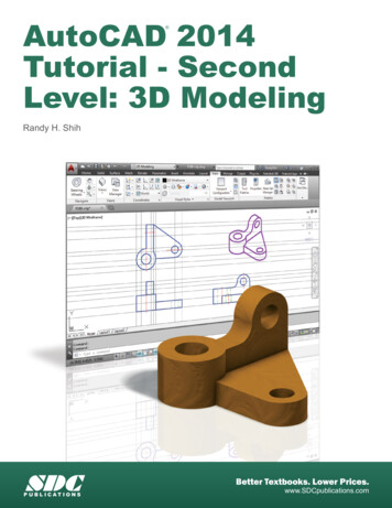
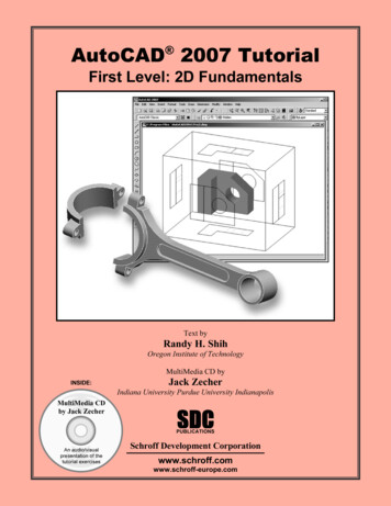
Geometric Construction Basics2-553215. We will create a freehand sketch of a fivepoint star using the Line command. We willcreate the sketch near the center of thedrawing window. Do not be overlyconcerned with the actual size or theaccuracy of your freehand sketch. Thisexercise is to give you a feel for theAutoCAD 2002 user interface.46. We will start at a location about one-third from thebottom of the graphics window. Left-click once toposition the starting point of our first line. This will bepoint 1 of our sketch. Next move the cursor upward andtoward the right side of point 1. Notice the rubber-bandline that follows the graphics cursor in the graphicswindow. Left-click again (point 2) and we have createdthe first line of our sketch.7. Move the cursor to the left of point 2 and create a horizontal line about thesame length as the first line on the screen.8. Repeat the above steps and complete the freehand sketch by adding threemore lines (from point 3 to point 4, point 4 to point 5, and then connect topoint 5 back to point 1).9. Notice that the Line command remains activated evenafter we connected the last segment of the line to thestarting point (point 1) of our sketch. Inside thegraphics window, click once with the right-mousebutton and a popup menu appears on the screen.10. Select Enter with the left-mouse-button to end theLine command. (This is equivalent to hitting the[ENTER] key on the keyboard. Note that the rightmouse-click brings up the option menu which providesmore options and we should become used to using it.)11. On your own, move the cursor near point 2 and point 3, and estimate thelength of the horizontal line by watching the displayed coordinates for eachpoint at the bottom of the screen.
2-6AutoCAD 2002 TutorialVisual referenceThe method we just used to create the freehand sketch is known as the interactivemethod, where we use the cursor to specify locations on the screen. This method isperhaps the fastest way to specify locations on the screen. However, it is rather difficultto try to create a line of a specific length by watching the displayed coordinates. It wouldbe helpful to know what one-inch or one-meter looks like on the screen while we arecreating entities. AutoCAD 2002 provides us with many tools to aid the construction ofour designs. We will use the Grid and Snap options to get a visual reference as to thesize of objects and learn to restrict the movement of the cursor to a set increment on thescreen.The Status Bar area is located at the bottom of the AutoCAD drawing screen. The wordsSNAP, GRID, ORTHO, POLAR, OSNAP, OSNAP, OTRACK, LWT and MODELappearing to the right of the coordinates are buttons that we can left-click to turn thesespecial options ON and OFF. When the corresponding button is highlighted, the specificoption is turned ON. These buttons act as toggle switches; each click of the button willtoggle the option ON or OFF. Using the buttons is a quick and easy way to make changesto these drawing aid options. We can toggle the options on and off in the middle ofanother command.Option ButtonsGRID ON1. Left-click the GRID button in the Status Bar to turn ON the GRID option. (Noticein the command prompt area, the message “ Grid on ” is also displayed.)
Geometric Construction Basics2-72. Move the cursor inside the graphics window, and estimate the distance in betweenthe grid points by watching the coordinates display at the bottom of the screen. The GRID option creates a pattern of dots that extends over an area on the screen.Using the grid is similar to placing a sheet of grid paper under a drawing. The gridhelps you align objects and visualize the distance between them. The grid is notdisplayed in the plotted drawing. The default grid spacing, which means the distancein between two dots on the screen, is 0.5 inches. We can see that the sketchedhorizontal line in the above sketch is about 3.5 inches long.SNAP ON1. Left-click the SNAP button in the Status Bar to turn ON the SNAP option.
2-8AutoCAD 2002 Tutorial2. Move the cursor inside the graphics window, and move the cursor diagonallyon the screen. Observe the movement of the cursor and watch the coordinatesdisplay at the bottom of the screen. The SNAP option controls an invisible rectangular grid that restricts cursormovement to specified intervals. When SNAP mode is on, the screen cursor andall input coordinates are snapped to the nearest point on the grid. The default snapinterval is 0.5 inches, and aligned to the grid points on the screen.3. Click on the Line icon in the Draw toolbar. In thecommand prompt area, the message “ line Specifyfirst point:” is displayed.4. Create another sketch of the five-point star with theGRID and SNAP options switched on.5. Use the right-mouse-button and select Enter in thepopup menu to end the Line command if you havenot done so.6. In the command prompt area, notice that “Command:” is displayed. Thisindicates that AutoCAD is waiting for us to activate the next desiredcommand.
Geometric Construction Basics2-9Using the ERASER One of the advantages of using a CAD system is the ability to remove entities withoutleaving any marks. We will erase two of the lines using the Erase command.1. Pick Erase in the Modify toolbar. (The icon is thefirst icon in the Modify toolbar. The icon is a pictureof an eraser at the end of a pencil.) The message“Select objects” is displayed in the commandprompt area and AutoCAD awaits us to select theobjects to erase.2. Left-click the SNAP button on the Status Bar to turn off the SNAP option sothat we can more easily move the cursor on top of objects. We can toggle theStatus Bar options ON or OFF in the middle of another command.3. Select any two lines on the screen, and right-mouse-click once to accept theselections. The selected two lines are erased.Repeat the last command1. Inside the graphics window, click once with the rightmouse-button to bring up the popup option menu.2. Pick Repeat Erase, with the left-mouse-button, in thepopup menu to repeat the last command. Notice the otheroptions available in the popup menu. AutoCAD 2002 offers many options to accomplish thesame task. Throughout this text, we will emphasize the useof the AutoCAD Heads-up DesignTM interface, whichmeans we focus on the screen, not on the keyboard.
2-10AutoCAD 2002 Tutorial3. Move the cursor to a location that is above and toward the left side of theentities on the screen. Left-mouse-click once to start a corner of a rubber-bandwindow.First cornerSecond corner4. Move the cursor toward the right and below the entities, and then left-mouseclick to enclose all the entities inside the selection window. Notice all entitiesthat are inside the window are selected.5. Inside the graphics window, right-mouse-click to proceed with erasing theselected entities. On your own, create a sketch of your choice using the Line command.Experiment with using the different commands we have discussed so far, such asswitching the GRID and SNAP options on and off in the middle of a command. Do not be in a hurry to rush through the tutorials. Build up your CAD skills byfamiliarizing yourself with the commands and options demonstrated, along withthe concepts discussed in the lessons. Feel free to repeat, at any time, any portionsof the lessons.
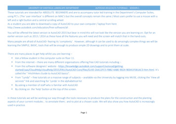
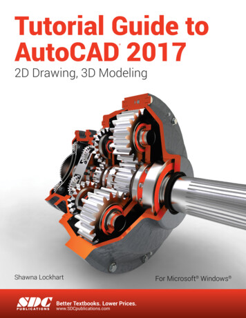
Geometric Construction Basics2-11The CAD Database and the User Coordinate System Designs and drawings created in a CAD system areusually defined and stored using sets of points inwhat is called world space. In most CAD systems,the world space is defined using a three-dimensionalCartesian coordinate system. Three mutuallyperpendicular axes, usually referred to as the X, Y,and Z axes, define this system. The intersection ofthe three coordinate axes forms a point called theorigin. Any point in world space can then be definedas the distance from the origin in the X, Y and Zdirections. In most CAD systems, the directions ofthe arrows shown on the axes identify the positivesides of the coordinates.A CAD file, which is the electronic version of the design, contains data that describethe entities created in the CAD system. Information such as the coordinate values inworld space for all endpoints, center points, etc., along with the descriptions of thetypes of entities are all stored in the file. Knowing that AutoCAD stores designs bykeeping coordinate data helps us understand the inputs required to create entities.3D UCS iconThe icon near the bottom left corner of the default AutoCAD graphics window showsthe positive X-direction and positive Y-direction of the coordinate system that isactive. In AutoCAD, the coordinate system that is used to create entities is called theUser Coordinate System (UCS). By default, the User Coordinate System is alignedto the world coordinate system (WCS). The world coordinate system is a coordinatesystem used by AutoCAD as the basis for defining all objects and other coordinatesystems defined by the users. We can think of the origin of the world coordinatesystem as a fixed point being used as a reference for all measurements. The defaultorientation of the Z-axis can be considered as positive values in front of the monitorand negative values inside the monitor.
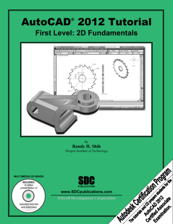
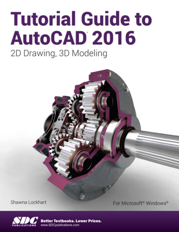
2-12AutoCAD 2002 TutorialChanging to the 2D UCS icon Display In AutoCAD 2002, the UCS icon is displayed in various ways to help usvisualize the orientation of the drawing plane.1. In the pull-down menus, select:[View] [Display] [UCSIcon] [Properties]2. In the UCS icon style section,switch to the 2D option as shown.3. Click OK to accept the settings. Note the W symbol in the UCS iconindicates the UCS is aligned to theworld coordinate system.
Geometric Construction Basics2-13Cartesian and Polar Coordinate SystemsIn a two-dimensional space,
AutoCAD 2002 Tutorial 2-1 Lesson 2 Geometric Construction Basics Create and Save AutoCAD drawing files. Use the AutoCAD visual reference commands. Draw, using the LINE and CIRCLE commands. Use the ERASE command. Define Positions using the Basic Entry methods. Use the AutoCAD Pan Realtime option. 2-2 AutoCAD 2002 Tutorial Introduction Learning to use a CAD File Size: 2MBPage Count: 56People also search forsolidworks 2005 system requirementslist of autocad commandsjoining multiple lines in autocad 2002change autocad 2002 from autodesk to cla app to open .hlp filescommon autocad commands