Transcription
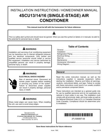
INSTALLATION INSTRUCTIONS / HOMEOWNER MANUAL4SCU13/14/16 (SINGLE-STAGE) AIRCONDITIONERThis manual must be left with the homeowner for future reference.This is a safety alert symbol and should never be ignored. When you see this symbol on labels or in manuals, be alert tothe potential for personal injury or death.Table of ContentsWARNINGInstallation and servicing of air conditioning equipmentcan be hazardous due to internal refrigerant pressureand live electrical components. Only trained andqualified service personnel should install or servicethis equipment. Installation and service performed byunqualified persons can result in property damage,personal injury, or death.WARNINGELECTRICAL SHOCK HAZARD!Risk of electrical shock. Disconnect allremote power supplies before installingor servicing any portion of the system.Failure to disconnect power suppliescan result in property damage, personalinjury, or death.WARNINGSharp metal edges can cause injury. When installingthe unit, use care to avoid sharp edges.General.1Installation.2Refrigeration Piping.4Electrical Wiring.12Start-Up.13Maintenance.14Homeowner Information.15Wiring Diagram.16GeneralRead this entire instruction manual, as well as theinstructions supplied in separate equipment, beforestarting the installation. Observe and follow all warnings,cautions, instructional labels, and tags. Failure to complywith these instructions could result in an unsafe conditionand/or premature component failure.These instructions are intended as a general guide onlyfor use by qualified personnel and do not supersede anynational or local codes in any way. The installation mustcomply with all provincial, state, and local codes as well asthe National Electrical Code (U.S.) or Canadian ElectricalCode (Canada). Compliance should be determined priorto installation.Manufactured ByAllied Air Enterprises LLCA Lennox International, Inc. Company215 Metropolitan DriveWest Columbia, SC 29170*P506957-05*(P) 506957-05Save these instructions for future reference506957-05Issue 1946Page 1 of 19
This unit uses R-410A, which is an ozone-friendly HFCrefrigerant. The unit must be installed with a matchingindoor coil and line set. A filter drier approved for use withR-410A is installed in the unit.When servicing or repairing HVAC components, ensurethe fasteners are appropriately tightened. Table 1 showstorque values for fasteners.FastenerTorqueStem Caps8 ft. lbs.Service Port Caps8 ft. lbs.Sheet Metal Screws16 in. lbs.#8 Machine Screws16 in. lbs.#10 Machine Screws28 in. lbs.Compressor Bolts90 in. lbs.InstallationNOTE: In some cases, noise in the living area has beentraced to gas pulsations from improper installation ofequipment. Locate unit away from windows, patios, decks, etc.where unit operation sounds may disturb customer. Leave some slack between structure and unit toabsorb vibration. Place a sound-absorbing material, such as Isomode,under the unit if it will be installed in a location orposition that will transmit sound or vibration to theliving area or adjacent buildings. In heavy snow areas, do not locate the unit wheredrifting snow will occur. The unit base should beelevated above the depth of average snows.Table 1. Torque TableNOTE: Elevation of the unit may be accomplishedby constructing a frame using suitable materials. If asupport frame is constructed, it must not block drainholes in unit base.Inspection of ShipmentUpon receipt of equipment, carefully inspect it for possibleshipping damage. If damage is found, it should be notedon the carrier’s freight bill. Take special care to examinethe unit inside the carton if the carton is damaged. Anyconcealed damage discovered should be reported to thelast carrier immediately, preferably in writing, and shouldinclude a request for inspection by the carrier’s agent.If any damages are discovered and reported to the carrierDO NOT INSTALL THE UNIT, as claim may be denied.Check the unit rating plate to confirm specifications are asordered.Safety PrecautionsFollow all safety codes. Wear safety glasses and workgloves. Use quenching cloth for brazing operations.Have fire extinguisher available. Read these instructionsthoroughly and follow all warning or cautions attached tothe unit.1.Always wear proper personal protection equipment.2.Always disconnect electrical power before removingpanel or servicing equipment.3.Keep hands and clothing away from moving parts.4.Handle refrigerant with caution; refer to proper MSDSfrom refrigerant supplier.5.Use care when lifting, avoid contact with sharp edges.Page 2 of 19 When installed in areas where low ambienttemperatures exist, locate unit so winter prevailingwinds do not blow directly into outdoor coil. Locate unit away from overhanging roof lines whichwould allow water or ice to drop on, or in front of, coilor into unit.When outdoor unit is connected to factory-approved indoorunit, outdoor unit contains system refrigerant charge foroperation with matching indoor unit when connected by 15ft. of field-supplied tubing. For proper unit operation, checkrefrigerant charge using charging information located oncontrol box cover.Outdoor SectionZoning ordinances may govern the minimum distance thecondensing unit can be installed from the property line.Install on a Solid, Level Mounting PadThe outdoor section is to be installed on a solid foundation.This foundation should extend a minimum of 2” (inches)beyond the sides of the outdoor section. To reduce thepossibility of noise transmission, the foundation slabshould NOT be in contact with or be an integral part of thebuilding foundation. See Figure 1.If conditions or local codes require the unit be attached topad or mounting frame, tie down bolts should be used andsecured to unit base pan.Issue 1946506957-05
Discharge AirBuildingStructure24”Mounting Slab6”*Ground LevelMounting slab must slope slightly away frombuilding, not to exceed 1/4” per foot.30” aroundControlBoxFigure 1. Slab MountingNOTE: See Table 2 for specific minimumclearance guidelines.Elevate UnitFigure 2.CAUTIONDO LOCATE THE UNIT:Accumulation of water and ice in base pan may causeequipment damage.Elevate unit per local climate and code requirements toprovide clearance above estimated snowfall level andensure adequate drainage of unit. Use snow stand in areaswhere prolonged freezing temperatures are encountered.If conditions or local codes require the unit be attached topad or mounting frame, tie down bolts should be used andfastened through knockouts provided in unit base pan.Clearance RequirementsWhen installing, allow sufficient space for airflow clearance,wiring, refrigerant piping, and service. For proper airflow,quiet operation and maximum efficiency. Position so water,snow, or ice from roof or eaves cannot fall directly on unit.Refer to Table 2 for installation clearances.LocationMinimum ClearanceService box30”Top of unit*48”Between units24”Against wall6”* Maximum soffit overhang is 36”.NOTE: At least one side should be unobstructed by a wall orother barrier.Table 2. Clearances506957-05 With proper clearances on sides and top of unit On a solid, level foundation or pad (unit must be levelto within 1/4 in./ft. per compressor manufacturerspecifications) To minimize refrigerant line lengthsDO NOT LOCATE THE UNIT: On brick, concrete blocks or unstable surfaces Near clothes dryer exhaust vents where debrisaccumulates Near sleeping area or near windows Under eaves where water, snow or ice can fall directlyon the unit With clearance less than 2 ft. from a second unit With clearance less than 4 ft. on top of unitRooftop InstallationsInstall unit at a minimum of 6” above surface of the roofto avoid ice buildup around the unit. Locate the unitabove a load bearing wall or area of the roof that canadequately support the unit. Consult local codes for rooftopapplications.If unit cannot be mounted away from prevailing winds, awind barrier should be constructed. Due to variation ininstallation applications, size and locate barrier accordingto the best judgment of the installer.Issue 1946Page 3 of 19
Use only refrigerant grade copper tubes.Be extra careful with sharp bends. Tubing can “kink” veryeasily, and if this occurs, the entire tube length will haveto be replaced. Extra care at this time will eliminate futureservice problems. Split systems may be installed with up to 50 feet ofline set (no more than 20 feet vertical) without specialconsideration (see long line set guidelines). Ensure that vapor and liquid tube diameters areappropriate to capacity of unit.It is recommended that vertical suction risers not be upsized. Proper oil return to the compressor should bemaintained with suction gas velocity. Run refrigerant tubes as directly as possible byavoiding unnecessary turns and bends. When passing refrigerant tubes through the wall, sealopening with RTV or other silicon-based caulk.The filter drier is very important for proper system operationand reliability. If the drier is shipped loose, it must beinstalled by the installer in the field. Unit warranty will bevoid, if the drier is not installed. Avoid direct tubing contact with water pipes, duct work,floor joists, wall studs, floors, walls, and any structure.Installation of Line Sets Do not suspend refrigerant tubing from joists andstuds with a rigid wire or strap that comes in directcontact with tubing. Ensure that tubing insulation is pliable and completelysurrounds vapor tube.Refrigeration PipingIt is important that no tubing be cut or seals broken until youare ready to actually make connections to the evaporatorand to the condenser section. DO NOT remove rubberplugs or copper caps from the tube ends until ready tomake connections at evaporator and condenser. Under nocircumstances leave the lines open to the atmosphere forany period of time, if so unit requires additional evacuationto remove moisture.ModelFilter DrierDO NOT fasten liquid or suction lines in direct contact withthe floor or ceiling joist. Use an insulated or suspensiontype of hanger. Keep both lines separate, and alwaysinsulate the suction line. Liquid line runs (30 feet or more)in an attic will require insulation. Route refrigeration linesets to minimize length.DO NOT let refrigerant lines come in direct contact withfoundation. When running refrigerant lines through thefoundation or wall, openings should allow for a soundand vibration absorbing material to be placed or installedbetween tubing and foundation. Any gap betweenfoundation or wall and refrigerant lines should be filled witha vibration damping material.13/14/16 SEERCAUTIONLiquid LineSuction /8473/87/8483/87/8593/81-1/81. On fully cased coils, remove the coil access andplumbing panels.603/81-1/82.Remove any shipping clamps from the liquid line anddistributor assembly.3.Disconnect the equalizer line from the check expansionvalve equalizer line fitting on the vapor line.4.Remove the vapor line sensing bulb.5.Disconnect the liquid line from the check expansionvalve at the liquid line assembly.6.Disconnect the check expansion valve from the liquidline orifice housing. Take care not to twist or damagedistributor tubes during this process.Issue 1946506957-05* Fittings should be supplied by the installer.Table 3.Page 4 of 19If ANY refrigerant tubing is required to be buried by stateor local codes, provide a 6 inch vertical rise at servicevalve.Installation into an Existing R-22 SystemIf the unit will be installed in an existing system that usesan indoor unit or line sets charged with R-22 refrigerant,installer must perform the following procedures to convertthe system to an R-410A system.Remove Existing Expansion Valve
7.Remove and discard check expansion valve and thetwo Teflon rings (see Figure 3).8.Use a field-provided fitting to temporarily reconnect theliquid line to the indoor unit’s liquid line orifice housing.TWO-PIECE PATCH PLATE(UNCASED COIL ONLY)DISTRIBUTORTUBESSTUB ENDLIQUID LINEORIFICEHOUSINGNOTEIn lieu of R-410A, an industry-standard flushing agentmay also be used.CHECKEXPANSIONVALVETEFLON RINGTEFLON RINGDISTRIBUTORASSEMBLYACYLINDER CONTAININGCLEAN R-410A TO BEUSED FOR FLUSHING(Positioned to deliver LIZERLINELIQUID LINE SERVICEVALVERECOVERYCYLINDERLIQUID LINEASSEMBLY WITHBRASS NUTSENSING BULBVAPORLINEDLIQUIDLINEVAPORLIQUIDMALE EQUALIZERLINE FITTINGHIGHNEWOUTDOORUNITVAPOR LINESERVICE ETDISCHARGERECOVERY MACHINEFigure 3. Remove Existing Expansion Valve(uncased coil shown)Flushing Line SetsIf the unit will be installed in an existing system that usesan indoor unit or line sets charged with R-22 refrigerant,installer must perform the following flushing procedure.NOTE: Existing system components (including line setand indoor coil) must be an AHRI match with the unit inorder to fulfill unit warranty requirements.WARNINGACylinder with clean R-410A (positioned to deliver liquid refrigerant) to thevapor service valve.BRefrigerant gauge set (low side) to the liquid line valve.CRefrigerant gauge set center port to inlet on the recovery machine withan empty recovery tank connected to the gauge set.DConnect recovery tank to recovery machine per machine instructions.Figure 4.1. Connect gauges and equipment as shown in Figure 4.2.Set the recovery machine for liquid recovery and startthe recovery machine. Open the gauge set valves toallow the recovery machine to pull a vacuum on theexisting system line set and indoor unit coil.3.Position the cylinder of clean R-410A for delivery ofliquid refrigerant and open its valve to allow liquidrefrigerant to flow into the system through the vaporline valve. Allow the refrigerant to pass from thecylinder and through the line set and the indoor unitcoil before it enters the recovery machine.4.After all of the liquid refrigerant has been recovered,switch the recovery machine to vapor recovery sothat all of the R-410A vapor is recovered. Allow therecovery machine to pull the system down to 0.5.Close the valve on the inverted R-410A drum and thegauge set valves. Pump the remaining refrigerant outof the recovery machine and turn the machine off.Issue 1946Page 5 of 19Refrigerant must be reclaimed in accordance withnational and local codes.CAUTIONDo NOT attempt to flush and re-use existing line setsor indoor coil when the system contains contaminants(i.e., compressor burn out).NOTE“Clean refrigerant” is any refrigerant in a system thathas not had compressor burnout. If the system hasexperienced burnout, it is recommended that theexisting line set and indoor coil be replaced.506957-05
Refrigerant Piping - Install Indoor Expansion ValveThis outdoor unit is designed for use in systems that include an expansion valve metering device (purchased separately) atthe indoor coil. See the Product Specifications for approved expansion valve kit match-ups and application information. Thecheck expansion valve unit can be installed internal or external to the indoor coil. In applications where an uncased coil isbeing installed in a field-provided plenum, install the check/expansion valve in a manner that will provide access for futurefield service of the expansion valve. Refer to below illustration for reference during installation of expansion valve unit.INDOOR EXPANSION VALVE INSTALLATIONTWO PIECEPATCH PLATE(UNCASEDCOIL ONLY)DISTRIBUTORTUBES(Uncased Coil Shown)LIQUID LINEORIFICEHOUSINGSTUBENDCHECKEXPANSIONVALVETEFLON RINGTEFLON SING BULB INSTALLATIONLIQUID LINEASSEMBLY WITHBRASS NUTMALE EQUALIZER LINEFITTING (SEEEQUALIZER LINEINSTALLATION FORFURTHER DETAILS)1/2 Turn3 - Install one of the provided Teflon rings around thestubbed end of the check expansion valve and lightly11 12 1lubricate the connector threads and expose surface of 102 the Teflon ring with refrigerant oil.9344 - Attach the stubbed end of the check expansion valve to 87 6 5the liquid line orifice housing. Finger tighten and use anappropriately sized wrench to turn an additional 1/2 turnclockwise as illustrated in the figure above, or tighten to20 ft-lb.5 - Place the remaining Teflon washer around the otherend of the check expansion valve. Lightly lubricateconnector threads and expose surface of the Teflon ring with refrigerant oil.6 - Attach the liquid line assembly to the check expansionvalve. Finger tighten and use an appropriately sizedwrench to turn an additional 1/2 turn clockwise asillustrated in the figure above or tighten to 20 ft-lb.1 - Attach the vapor line sensing bulb in the properorientation as illustrated to the right using the clamp andscrews provided.VAPORLINELIQUID LINESensing bulb insulation is required ifmounted external to the coil casing. sensingbulb installation for bulb positioning.EQUALIZER LINE INSTALLATIONNOTE - Though it is preferred to have the sensing bulb1/8 Turninstalled on a horizontal run of the vapor line, installationon a vertical run of piping is acceptable if necessary.11 12 12NOTE - Confirm proper thermal contact between vapor 103line and check/expansion bulb before insulating the 948sensing bulb once installed.57 62 - Connect the equalizer line from the check expansionvalve to the equalizer vapor port on the vapor line. Fingertighten the flare nut plus 1/8 turn (7 ft-lbs) as illustratedbelow.ON LINES SMALLER THAN7/8”, MOUNT SENSINGBULB AT EITHER THE 3 OR9 O'CLOCK POSITION.VAPOR LINE1 - Remove and discard either the flare seal cap or flare nutwith copper flare seal bonnet from the equalizer line porton the vapor line as illustrated in the figure below.2 - Remove the field-providedBULB12BULBsembly.FLARE SEAL CAPFLARE NUTVAPOR LINEORCOPPER FLARESEAL BONNETON 7/8” AND LARGER LINES,MOUNT SENSING BULB ATEITHER THE 4 OR 8 O'CLOCKPOSITION.12MALE BRASS EQUALIZERLINE FITTINGBULBBULBVAPOR LINENOTE - NEVER MOUNT THE SENSING BULB ONBOTTOM OF LINE.Page 6 of 19Issue 1946506957-05
Refrigerant Piping - Brazing Procedures21CUT AND DEBURCut ends of the refrigerant lines square (free from nicks or dents)and debur the ends. The pipe must remain round. Do not crimp endof the line.CAP AND CORE REMOVALRemove service cap and core fromboth the vapor and liquid line serviceports.CUT AND DEBURSERVICE PORTCAPSERVICEPORTCORELINE SET SIZE MATCHESSERVICE VALVE CONNECTIONCOPPER TUBESTUBSERVICEPORTCORESERVICE VALVECONNECTIONLINE SET SIZE IS SMALLERTHAN CONNECTIONREFRIGERANT LINEDO NOT CRIMP SERVICE VALVECONNECTOR WHEN PIPE ISSMALLER THAN CONNECTIONATTACH THE MANIFOLD GAUGE SET FOR BRAZING LIQUID AND VAPOR LINE SERVICE VALVESFlow regulated nitrogen (at 1 to 2 psig) through the low-side refrigeration gauge set into the liquid line service port valve, and out of thevapor line service port valve.A - Connect gauge set low pressure side toliquid line service valve (service port).B - Connect gauge set center port to bottle ofnitrogen with regulator.C - Remove core from valve in vapor lineservice port to allow nitrogen to escape.VAPOR SERVICE PORT MUST BE OPENTO ALLOW EXIT POINT FOR NITROGENVAPOR LINECLOWUSE REGULATOR TO FLOWNITROGEN AT 1 TO 2 PSIG.HIGHATTACHGAUGESBVAPOR LINESERVICEVALVEOUTDOORUNITINDOORUNITLIQUID LINELIQUID LINE SERVICEVALVEANITROGENWHEN BRAZING LINE SET TOSERVICE VALVES, POINT FLAMEAWAY FROM SERVICE VALVE.NOTEUse a manifold gauge set designed for use on R-410Arefrigerant systems.WARNINGBefore brazing, ensure the system is fullyrecovered of all refrigerant. Application of abrazing torch to a pressurized system mayresult in ignition of the refrigerant and oilmixture. Check the high and low pressuresbefore applying heat.506957-05VAPOR LINE SERVICEVALVELIQUID LINE SERVICEVALVEREDUCER3SERVICEPORT CAPWARNINGBrazing alloys and flux contain materials which arehazardous to your health.Avoid breathing vapors or fumes from brazingoperations. Perform operations only in well-ventilatedareas.Wear gloves and protective goggles or face shield toprotect against burns.Wash hands with soap and water after handling brazingalloys and flux.Issue 1946Page 7 of 19
456WRAP SERVICE VALVESTo help protect service valve seals during brazing, wrap water-saturated cloths around service valve bodies and copper tube stubs. Useadditional water-saturated cloths underneath the valve body to protect the base paint.FLOW NITROGENFlow regulated nitrogen (at 1 to 2 psig) through the refrigeration gauge set into the valve stem port connection on the liquid service valve andout of the vapor valve stem port. See steps 3A, 3B and 3C on manifold gauge set connections.BRAZE LINE SETWrap both service valves with water-saturated cloths as illustrated here and as mentioned in step 4, before brazing to line set.Cloths must remain water-saturated throughout the brazing and cool-down process.LIQUID LINE SERVICE VALVEWARNINGWhile protecting theservice valve seals withwater-saturated cloths,ensure that water doesNOT enter the system.WHEN BRAZING LINE SET TOSERVICE VALVES, POINT FLAMEAWAY FROM SERVICE VALVE.IMPORTANT — Allow braze joint to cool. Applyadditional water-saturated cloths to help cool brazedjoint. Do not remove water-saturated cloths untilpiping has cooled. Temperatures above 250ºF willdamage valve seals.WARNINGFIRE, PERSONAL INJURY, OR PROPERTY DAMAGEmay result if you do not wrap a water-saturated cloth aroundboth liquid and suction line service valve bodies and coppertube stub while brazing the line set! The braze, whencomplete, must be quenched with water to absorb anyresidual heat.Do not open service valves until refrigerant lines andindoor coil have been leak-tested and evacuated. Referto Leak Test and Evacuation section of this manual.WATER-SATURATEDCLOTHLIQUID LINEVAPOR LINESERVICE VALVEWHEN BRAZING LINE SET TOSERVICE VALVES, POINT FLAMEAWAY FROM SERVICE VALVE.VAPOR LINE7Page 8 of 19WATER-SATURATEDCLOTHPREPARATION FOR NEXT STEPAfter all connections have been brazed, disconnect manifold gauge set from service ports. Apply additional water-saturated cloths to bothservices valves to cool piping. Once piping is cool, remove all water-saturated cloths.Issue 1946506957-05
Leak Test and EvacuationLEAK TESTLOWHIGHMANIFOLD GAUGE SETOUTDOOR UNITABTO VAPORSERVICE VALVENOTE - Positioncanister to deliverliquid refrigerant.NITROGENHFC-410A1CONNECT GAUGE SETA - Connect the high pressure hose of an HFC-410A manifold gauge set to the vapor valve service port.NOTE - Normally, the high pressure hose is connected to the liquid line port. However, connecting itto the vapor port better protects the manifold gauge set from high pressure damage.B - With both manifold valves closed, connect the cylinder of HFC-410A refrigerant to the center port ofthe manifold gauge set.NOTE - Later in the procedure, the HFC-410A container will be replaced by the nitrogen container.2TEST FOR LEAKSAfter the line set has been connected to the indoor and outdoor units, check the line set connections andindoor unit for leaks. Use the following procedure to test for leaks:A - With both manifold valves closed, connect the cylinder of HFC-410A refrigerant to the center port of themanifold gauge set. Open the valve on the HFC-410A cylinder (vapor only).B - Open the high pressure side of the manifold to allow HFC-410A into the line set and indoor unit. Weigh ina trace amount of HFC-410A. [A trace amount is a maximum of two ounces (57 g) refrigerant or threepounds (31 kPa) pressure.] Close the valve on the HFC-410A cylinder and the valve on the highpressure side of the manifold gauge set. Disconnect the HFC-410A cylinder.C - Connect a cylinder of nitrogen with a pressure regulating valve to the center port of the manifold gaugeset.D - Adjust nitrogen pressure to 150 psig (1034 kPa). Open the valve on the high side of the manifold gauge setin order to pressurize the line set and the indoor unit.E - After a few minutes, open one of the service valve ports and verify that the refrigerant added to thesystem earlier is measurable with a leak detector.F - After leak testing, disconnect gauges from service ports.NOTE - Service valve cores remain removed for the following evacuation procedure.506957-05Issue 1946Page 9 of 19
3EVACUATIONCONNECT GAUGE SETLOWHIGHNOTE - Remove cores from service valves (if not already done).A - Connect low side of manifold gauge set with1/4 SAE in-line tee to vapor line service valveB - Connect high side of manifold gauge set toliquid line service valveC - Connect available micron gauge connectoron the 1/4 SAE in-line tee.D - Connect the vacuum pump (with vacuumgauge) to the center port of the manifoldgauge set. The center port line will be usedlater for both the HFC-410A and AUGETO VAPORSERVICE VALVENOTE - Positioncanister to deliverliquid refrigerant.HFC-410AVACUUM PUMPMANIFOLDGAUGE SET1/4 SAE TEE WITH SWIVELCOUPLERBTO LIQUID LINESERVICE VALVE4DEVACUATE THE SYSTEMRECOMMENDMINIMUM 3/8” HOSEA - Open both manifold valves and start the vacuum pump.B - Evacuate the line set and indoor unit until a slight vacuum is indicated on the micron gauge (approximately 23,000 microns or29.01 inches of mercury).NOTE - During the early stages of evacuation, it is desirable to close the manifold gauge valve at least once. A rapid rise in pressureindicates a relatively large leak. If this occurs, repeat the leak testing procedure.NOTE - The term absolute pressure means the total actual pressure above absolute zero within a given volume or system. Absolutepressure in a vacuum is equal to atmospheric pressure minus vacuum pressure.C - When the absolute pressure reaches 23,000 microns (29.01 inches ofmercury), perform the following:Close manifold gauge valves.Possible equipment damage.Close valve on vacuum pump.Avoid deep vacuum operation. Do not useTurn off vacuum pump.compressors to evacuate a system.Disconnect manifold gauge center port hose from vacuum pump.Attach manifold center port hose to a nitrogen cylinder with pressure Extremely low vacuum can cause internalarcing and compressor failure. Damageregulator set to 150 psig (1034 kPa) and purge the hose.Open manifold gauge valves to break the vacuum in the line set and indoor caused by deep vacuum operation willunit.void warranty.Close manifold gauge valves.D - Shut off the nitrogen cylinder and remove the manifold gauge hose from the cylinder. Open the manifold gauge valves to release thenitrogen from the line set and indoor unit.E - Reconnect the manifold gauge to the vacuum pump, turn the pump on, and continue to evacuate the line set and indoor unit until theabsolute pressure does not rise above 500 microns (29.9 inches of mercury) within a 20-minute period after shutting off the vacuum pumpand closing the manifold gauge valves.F - When the absolute pressure requirement above has been met, disconnect the manifold hose from the vacuum pump and connect it to acylinder of HFC-410A positioned to deliver liquid refrigerant. Open the manifold gauge valve 1 to 2 psig in order to release the vacuum in theline set and indoor unit.G - Perform the following:1/6 TURNClose manifold gauge valves.Shut off HFC-410A cylinder.12 111Reinstall service valve cores by removing manifold hose from service valve. Quickly install cores with core210tool while maintaining a positive system pressure.93Replace stem caps and finger tighten them, then tighten an additional one-sixth (1/6) of a turn as illustrated.48H - Open suction service valve first before liquid valve to release the unit charge into the system. Replace valve57caps and tighten (8 ft. lb.). Caps are the primary seal.6WARNING !Page 10 of 19Issue 1946506957-05
Liquid and Suction Line Service ValvesThe liquid line and suction line service valves (see Figure5) and service ports are used for leak testing, evacuation,charging, and checking charge.Each valve is equipped with a service port which has afactory-installed Schrader valve. A service port cap protectsthe Schrader valve from contamination and serves as theprimary leak seal.To Access the Schrader Port:1.Remove the service port cap with an adjustablewrench.2.Connect gauge to the service port.3.When testing is completed, replace service port cap.Tighten finger tight, then an additional 1/6 turn.To Open Liquid or Suction Line Service Valve:1.Remove stem cap with an adjustable wrench.2.Use service wrench with a hex-head extension to backthe stem out counterclockwise as far as it will go. Use a3/16” hex head extension for liquid line service valvesand a 5/16” extension for suction line service valves.3.Replace the stem cap. Tighten finger tight, then tightenan additional 1/6 turn.To Close Liquid or Suction Line Service Valve:1.Remove the stem cap with an adjustable wrench.2.Use a service wrench with a hex-head extension toturn the stem clockwise to seat the valve. Tightenfirmly.3.Figure 5.Replace the stem cap. Tighten finger tight, then tightenan additional 1/6 turn.Suction Line (Ball Type) Service ValveSuction line (ball type) service valves function the sameway as the other valves; the difference is in the construction(see Figure 6).The ball valve is equipped with a service port with a factoryinstalled Schrader valve. A service port cap protects theSchrader valve from contamination and serves as theprimary seal.Figure 6.506957-05Issue 1946Page 11 of 19
Electrical Wiring3.Ground unit at unit disconnect switch or to an earthground. To facilitate conduit, a hole is in the bottomof the control box. Connect conduit to the control boxusing a proper conduit fitting. Units are approved foruse only with copper conductors. 24V Class II
Save these instructions for future reference INSTALLATION INSTRUCTIONS / HOMEOWNER MANUAL 4SCU13/14/16 (SINGLE-STAGE) AIR CONDITIONER (P) 506957-05 Allied Air Enterprises LLC Manufactured By *P506957-05* A Lennox International, Inc. Company 215 Metropolitan Drive West Columbia, SC 29170 This manual must be left with the homeowner for future .