Transcription
INSTALLATION INSTRUCTIONSA95UH, A93UH, 95G1UH & 92G1UHWarm Air Gas FurnaceUpflow/Horizontal Left and Right Air DischargeThis manual must be left with the homeowner for future reference.This is a safety alert symbol and should never be ignored. When you see this symbol on labels or inmanuals, be alert to the potential for personal injury or death.WARNINGCAUTIONImproper installation, adjustment, alteration, service ormaintenance can cause property damage, personal injuryor loss of life. Installation and service must be performedby a licensed professional installer (or equivalent), serviceagency or the gas supplier.As with any mechanical equipment, personal injury canresult from contact with sharp sheet metal edges. Becareful when you handle this equipment.TABLE OF CONTENTSUnit Dimensions . 2A95/A93/95G1/92G1UH Parts Arrangement . 3A95/A93/95G1/92G1UH Gas Furnace . 4Shipping and Packing List . 4Safety Information . 4Use of Furnace as a Construction Heater . 5General . 6Combustion, Dilution, Ventilation Air . 6Setting Equipment . 9Filters . 13Duct System . 13Pipe and Fittings Specifications . 13Joint Cementing Procedure . 15Venting Practices . 16Vent Piping Guidelines . 17Gas Piping . 35Electrical . 38Unit Start Up . 41Gas Pressure Adjustment . 43High Altitude Information . 43Other Unit Adjustments . 46Blower Motor Performance . 47Service . 51Planned Service . 53Diagnostic Codes . 53Repair Parts List . 54Start Up Checklist . 55*P506724-01*Manufactured ByAllied Air Enterprises, Inc.A Lennox International, Inc. Company215 Metropolitan DriveWest Columbia, SC 29170(P) 506724-01506724-01Issue 1108Page 1 of 57
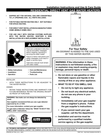
A95UH, A93UH, 95G1UH & 92G1UH Unit Dimensions - inches (mm)1 NOTE - 20C and 20D (5 Ton) size units installed in upflowapplications that require air volumes of 1800 cfm (850 L/s) orgreater must have one of the following:1. Single side return air with transition, to accommodate20 x 25 x 1 in. (508 x 635 x 25 mm) cleanable air filter.(Required to maintain proper air velocity.)2. Single side return air with optional “RAB” Return AirBase.3. Bottom return air.4. Return air from both sides.5. Bottom and one side return air.See “Blower Performance Tables” for additional information.2 Optional External Side Return Air Filter kit is not for use withoptional Return Air Base.* Consider sizing requirements for optional IAQ equipmentbefore cutting side return opening.FRONT VIEWSIDE VIEWModelA95UH/A93UH95G1UH/92G1UHPage 2 of 223-3/85942358411-1/8283Issue 1108506724-01
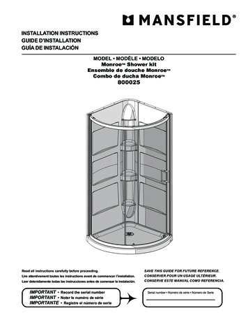
EXPANDED VIEWFigure 1506724-01Issue 1108Page 3 of 57
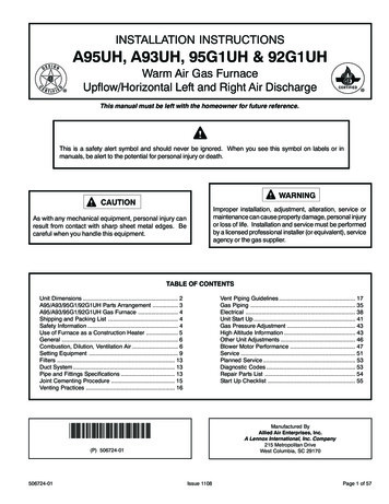
A95UH, A93UH, 95G1UH &92G1UH Gas FurnaceThe A95UH/A93UH/95G1UH & 92G1UH Category IV gasfurnace is shipped ready for installation in the upflow orhorizontal position. The furnace is shipped with the bottompanel in place. The bottom panel must be removed if theunit is to be installed in horizontal or upflow applications withbottom return air.Safety InformationWARNINGImproper installation, adjustment, alteration, service ormaintenance can cause property damage, personal injuryor loss of life. Installation and service must be performedby a licensed professional installer (or equivalent), serviceagency or the gas supplier.The A95UH/A93UH/95G1UH & 92G1UH can be installedas either a Direct Vent or a Non-Direct Vent gas centralfurnaceCAUTIONThe furnace is equipped for installation in natural gasapplications. A conversion kit (ordered separately) is requiredfor use in propane/LP gas applications.As with any mechanical equipment, personal injury canresult from contact with sharp sheet metal edges. Becareful when you handle this equipment.NOTE: In Direct Vent installations, combustion air is takenfrom outdoors and flue gases are discharged outdoors. InNon-Direct Vent installations, combustion air is taken fromindoors and flue gases are discharged outdoors. See Figure2 for applications involving roof termination.DANGERDANGER OF EXPLOSION!There are circumstances in which odorant used with LP/Propane gas can lose its scent. In case of a leak, LP/Propane gas will settle close to the floor and may be difficultto smell. An LP/Propane leak detector should be installedin all LP applications.Use only the type of gas approved for use with this furnace.Refer to unit nameplate.A95UH/A93UH/95G1UH & 92G1UH units are CSAInternational certified to ANSI Z21.47 and CSA 2.3 standards.Building CodesIn the USA, installation of gas furnaces must conform withlocal building codes. In the absence of local codes, unitsmust be installed according to the current National Fuel GasCode (ANSI Z223.1/NFPA 54). The National Fuel Gas Codeis available from the American National StandardsInstitute, Inc., 11 West 42nd Street, New Your, NY 10036.Figure 2Shipping and Packing List1 - Assembled Gas Furnace1 - Bag assembly containing the following:3 - Wire nuts1 - Snap bushing1 - Snap Plug1 - Wire tie1 - Condensate trap1 - Condensate trap cap1 - Condensate trap clamp1 - 2” diameter debris screenIn Canada, installation must conform with current NationalStandard of Canada CSA-B149 Natural Gas and PropaneInstallation Codes, local plumbing or waste water codes andother applicable local codes.In order to ensure proper unit operation in non-direct ventapplications, combustion and ventilation air supply must beprovided according to the current National Fuel Gas Codeor CSA-B149 standard.Check equipment for shipping damage. If you find anydamage, immediately contact the last carrier.Please refer to specification sheets for available accessories.Page 4 of 57Issue 1108506724-01
Installation LocationsThis furnace is CSA International certified for installationclearances to combustible material as listed on the unitnameplate and in the table in Figure 10. Accessibility andservice clearances must take precedence over fire protectionclearances.Heating Unit Installed Parallel to Air Handler UnitDampers(open during heating operation only)Gas UnitNOTE: For installation on combustible floors, the furnaceshall not be installed directly on carpeting, tile, or othercombustible material other than wood flooring.AIR FLOWAir Handler UnitFor installation in a residential garage, the furnace must beinstalled so that the burner(s) and the ignition source arelocated no less than 18 inches (457 mm) above the floor.The furnace must be located or protected to avoid physicaldamage by vehicles. When a furnace is installed in a publicgarage, hangar, or other building that has a hazardousatmosphere, the furnace must be installed according torecommended good practice requirements and currentNational Fuel Gas Code or CSA B149 standards.Dampers(open during cooling operation only)Heating Unit Installed Upstream of Cooling CoilAIR FLOWInstalled in Combination with a Cooling CoilWhen this furnace is used with cooling units (Figure 3), itshall be installed in parallel with, or on the upstream side of,cooling units to avoid condensation in the heatingcompartment. With a parallel flow arrangement, a damper(or other means to control the flow of air) must adequatelyprevent chilled air from entering the furnace. If the damperis manually operated, it must be equipped to preventoperation of either the heating or the cooling unit, unless itis in the full HEAT or COOL setting.When installed, this furnace must be electrically groundedaccording to local codes. In addition, in the United States,installation must conform with the current National ElectricCode, ANSI/NFPA No. 70. The National Electric Code (ANSI/NFPA No. 70) is available from the following address:National Fire Protection Association1 Battery March ParkQuincy, MA 02269AIR FLOWFIGURE 3NOTE: This furnace is designed for a minimum continuousreturn air temperature of 60 F (16 C) or an intermittentoperation down to 55 F (13 C) dry bulb for cases where anight setback thermostat is used. Return air temperaturemust not exceed 85 F (29 C) dry bulb.This furnace may be installed in alcoves, closets, attics,basements, garages, and utility rooms in the upflow orhorizontal position.This furnace design has not been CSA certified for installationin mobile homes, recreational vehicles, or outdoors.Use of Furnace as a Construction HeaterThese units are not recommended for use as a constructionheater during any phase of construction. Very low return airtemperature, harmful vapors and operation of the unit withclogged or misplaced filters will damage the unit.These units may be used for heating of buildings or structuresunder construction, if the following conditions are met: The vent system must be permanently installed per theseinstallation instructions. A room thermostat must control the furnace. The use offixed jumpers that will provide continuous heating is notallowed. The return air duct must be provided and sealed to thefurnace. Return air temperature range between 60 F (16 C) and80 F (27 C) must be maintained.Issue 1108Page 5 of 57In Canada, all electrical wiring and grounding for the unitmust be installed according to the current regulations of theCanadian Electrical Code Part I (CSA Standard C22.1) and/or local codes.506724-01Gas UnitCooling CoilNote: Furnace must be adjusted to obtain a temperaturerise within the range specified on the unit nameplate. Failureto do so may cause erratic limit operation and prematureheat exchanger failure.This furnace must be installed so that its electricalcomponents are protected from water.AIR FLOW
Air filters must be installed in the system and must bemaintained during construction.Air filters must be replaced upon construction completion.The input rate and temperature rise must be set per thefurnace rating plate.One hundred percent (100%) outdoor air must be providedfor combustion air requirements during construction.Temporary ducting may supply outdoor air to the furnace.Do not connect duct directly to the furnace. Size thetemporary duct following the instructions in section forCombustion, Dilution and Ventilation Air in a confinedspace with air from outside.The furnace heat exchanger, components, duct system,air filters and evaporator coils must be thoroughlycleaned following final construction cleanup.All furnace operating conditions (including ignition, inputrate, temperature rise and venting) must be verifiedaccording to these installation instructions.WARNINGProduct Contains Fiberglass Wool.Disturbing the insulation in this product duringinstallation, maintenance, or repair will expose you tofiberglass wool. Breathing this may cause lung cancer.(Fiberglass wool is known to the State of California tocause cancer.)Fiberglass wool may also cause respiratory, skin, andeye irritation.To reduce exposure to this substance or for furtherinformation, consult material safety data sheets availablefrom address shown below, or contact your supervisor.Allied Air Enterprises, Inc.215 Metropolitan DriveWest Columbia, SC 29170GeneralThese instructions are intended as a general guide and donot supersede local codes in any way. Consult authoritieshaving jurisdiction before installation.In addition to the requirements outlined previously, thefollowing general recommendations must be consideredwhen installing one of these furnaces: Combustion, Dilution & Ventilation AirIf this unit is installed as a Non-Direct Vent Furnace,follow the guidelines in this section.NOTE: In Non-Direct Vent Installations, combustion air istaken from indoors and flue gases are discharged outdoors.Place the furnace as close to the center of the airdistribution system as possible. The furnace should alsobe located close to the vent termination point.When the furnace is installed in non-direct ventapplications, do not install the furnace where drafts mightblow directly into it. This could cause impropercombustion and unsafe operation.When the furnace is installed in non-direct ventapplications, do not block the furnace combustion airopening with clothing, boxes, doors, etc. Air is neededfor proper combustion and safe unit operation.When the furnace is installed in an attic or other insulatedspace, keep insulation away from the furnace.When the furnace is installed in an unconditioned space,consider provisions required to prevent freezing ofcondensate drain system.WARNINGInsufficient combustion air can cause headaches,nausea, dizziness or asphyxiation. It will also causeexcess water in the heat exchanger resulting in rustingand premature heat exchanger failure. Excessiveexposure to contaminated combustion air will result insafety and performance related problems. Avoidexposure to the following substances in the combustionair supply:Permanent wave solutionsChlorinated waxes and cleanersChlorine base swimming pool chemicalsWater softening chemicalsDe-icing salts or chemicalsCarbon tetrachlorideHalogen type refrigerantsCleaning solvents (such as perchloroethylene)Printing inks, paint removers, varnishes, etc.Hydrochloric acidCements and gluesAntistatic fabric softeners for clothes dryersMasonry acid washing materialsNote: The Commonwealth of Massachusetts stipulatesthese additional requirements: Gas furnaces shall be installed by a licensed plumberor fitter only.The gas cock must be “T handle” type.When a furnace is installed in an attic, the passagewayto and service area surrounding the equipment shall befloored.CAUTIONThese units should not be installed in areas normallysubject to freezing temperatures.Page 6 of 57In the past, there was no problem in bringing in sufficientoutdoor air for combustion. Infiltration provided all the airthat was needed. In today’s homes, tight constructionpractices make it necessary to bring in air from outside forcombustion. Take into account that exhaust fans, appliancevents, chimneys, and fireplaces force additional air that couldbe used for combustion out of the house. Unless outsideIssue 1108506724-01
air is brought into the house for combustion, negativepressure (outside pressure is greater than inside pressure)will build to the point that a down draft can occur in the furnacevent pipe or chimney. As a result, combustion gases enterthe living space creating a potentially dangerous situation.In the absence of local codes concerning air for combustionand ventilation, use the guidelines and procedures in thissection to install these furnaces to ensure efficient and safeoperation. You must consider combustion air needs andrequirements for exhaust vents and gas piping. A portion ofthis information has been reprinted with permission fromthe National Fuel Gas Code (ANSI-Z223.1/NFPA 54). Thisreprinted material is not the complete and official position ofANSI on the referenced subject, which is represented onlyby the standard in its entirely.In Canada, refer to the CSA B149 Installation codes.CAUTIONDo not install the furnace in a corrosive or contaminatedatmosphere. Meet all combustion and ventilation airrequirements, as well as all local codes.All gas-fired appliances require air for the combustionprocess. If sufficient combustion air is not available, thefurnace or other appliance will operate inefficiently andunsafely. Enough air must be provided to meet the needsof all fuel-burning appliances and appliances such as exhaustfans which force air out of the house. When fireplaces,exhaust fans, or clothes dryers are used at the same timeas the furnace, much more air is required to ensure propercombustion and to prevent a down draft. Insufficient aircauses incomplete combustion which can result in carbonmonoxide.infiltration. If the furnace is located in a building of tightconstruction with weather stripping and caulking around thewindows and doors, follow the procedures in the “Air fromOutside” section.Confined SpaceA confined space is an area with a volume less than 50cubic feet (1.42 m³) per 1,000 Btu (.29 kW) per hour of thecombined input rating of all appliances installed in that space.This definition includes furnace closets or small equipmentrooms.When the furnace is installed so that supply ducts carry aircirculated by the furnace to areas outside the spacecontaining the furnace, the return air must be handled byducts which are sealed to the furnace casing and whichterminate outside the space containing the furnace. This isespecially important when the furnace is mounted on aplatform in a confined space such as a closet or smallequipment room. Even a small leak around the base of theunit at the platform or at the return air duct connection cancause a potentially dangerous negative pressure condition.Air for combustion and ventilation can be brought into theconfined space either from inside the building or from outside.Air from InsideIf the confined space that houses the furnace adjoins a spacecategorized as unconfined, air can be brought in by providingtwo permanent openings between the two spaces. Eachopening must have a minimum free area of 1 square inch(645 mm²) per 1,000 Btu (.29 kW) per hour of total inputrating of all gas-fired equipment in the confined space. Eachopening must be at least 100 square inches (64516 mm²).One opening shall be within 12 inches (305 mm) of the topof the enclosure and one opening within 12 inches (305 mm)of the bottom. See Figure 4.In addition to providing combustion air, fresh outdoor airdilutes contaminants in the indoor air. These contaminantsmay include bleaches, adhesives, detergents, solvents andother contaminants which can corrode furnace components.EQUIPMENT IN CONFINED SPACE ALL AIR FROM INSIDEROOF TERMINATEDEXHAUST PIPEThe requirements for providing air for combustion andventilation depend largely on whether the furnace is installedin an unconfined or a confined space.Unconfined SpaceAn unconfined space is an area such as a basement orlarge equipment room with a volume greater than 50 cubicfeet (1.42 m³) per 1,000 Btu (.29 kW) per hour of thecombined input rating of all appliances installed in that space.This space also includes adjacent rooms which are notseparated by a door. Though an area may appear to beunconfined, it might be necessary to bring in outdoor air forcombustion if the structure does not provide enough air by506724-01Issue 1108SIDE WALLTERMINATEDEXHAUST PIPE(ALTERNATELOCATION)FURNACEOPENINGS(To AdjacentUnconfinedSpace)NOTE Each opening shall have a free area of at least one square inchper 1,000 Btu (645mm 2 per .29kW) per hour of the total input rating ofall equipment in the enclosure, but not less than 100 square inches(64516mm.2).FIGURE 4Page 7 of 57
Air from OutsideIf air from outside is brought in for combustion and ventilation,the confined space shall be provided with two permanentopenings. One opening shall be within 12” (305 mm) of thetop of the enclosure and one within 12” (305 mm) of thebottom. These openings must communicate directly or byducts with the outdoors or spaces (crawl or attic) that freelycommunicate with the outdoors or indirectly through verticalducts. Each opening shall have a minimum free area of 1square inch per 4,000 Btu (645 mm² per .59 kW) per totalinput rating of all equipment in the enclosure (See Figure 5).to 25 percent free area and metal louvers and grilles willhave 60 to 75 percent free area. Louvers and grilles mustbe fixed in the open position or interlocked with the equipmentso that they are opened automatically during equipmentoperation.EQUIPMENT IN CONFINED SPACE ALL AIR FROM OUTSIDE(All Air Through Ventilated Attic)ROOF TERMINATEDEXHAUST PIPEEQUIPMENT IN CONFINED SPACE ALL AIR FROM OUTSIDE(Inlet Air from Crawl Space and Outlet Air to Ventilated Attic)VENTILATION LOUVERS(Each end of attic)OUTLETAIRVENTILATION LOUVERS(Each end of attic)ROOF TERMINATEDEXHAUST PIPESIDE WALLTERMINATEDEXHAUST PIPE(ALTERNATELOCATION)OUTLETAIRSIDE WALLTERMINATEDEXHAUST PIPE(ALTERNATELOCATION)NOTE The inlet and outlet air openings shall each have a free area ofat least one square inch per 4,000 Btu (645mm2 per 1.17kW) per hourof the total input rating of all equipment in the enclosure.FURNACEINLETAIRINLET AIR(Ends 12" abovebottom)FURNACEVENTILATIONLOUVERS(For unheatedcrawl space)FIGURE 6NOTE The inlet and outlet air openings shall each have a free areaof at least one square inch per 4,000 Btu (645mm 2 per 1.17kW) perhour of the total input rating of all equipment in the enclosure.EQUIPMENT IN CONFINED SPACE ALL AIR FROM OUTSIDEFIGURE 5If air from outside is brought in for combustion and ventilation,the confined space must have two permanent openings. Oneopening shall be within 12 inches (305 mm) of the top of theenclosure and one opening within 12 inches (305 mm) ofthe bottom. These openings must communicate directly orby ducts with the outdoors or spaces (crawl or attic) thatfreely communicate with the outdoors or indirectly throughvertical ducts. Each opening shall have a minimum freearea of 1 square inch (645 mm²) per 4,000 Btu (1.17 kW)per hour of total input rating of all equipment in the enclosure.See Figures 5 and 6. When communicating with theoutdoors through horizontal ducts, each opening shall havea minimum free area of 1 square inch (645 mm²) per 2,000Btu (.56 kW) per total input rating of all equipment in theenclosure. See Figure 7.When ducts are used, they shall be of the same crosssectional area as the free area of the openings to whichthey connect. The minimum dimension of rectangular airducts shall be no less than 3 inches (75 mm). In calculatingfree area, the blocking effect of louvers, grilles, or screensmust be considered. If the design and free area of protectivecovering is not known for calculating the size openingrequired, it may be assumed that wood louvers will have 20Page 8 of 57Issue 1108ROOF TERMINATEDEXHAUST PIPEOUTLET AIRSIDE WALLTERMINATEDEXHAUST PIPE(ALTERNATELOCATION)FURNACEINLET AIRNOTE Each air duct opening shall have a free area of at least onesquare inch per 2,000 Btu (645mm 2 per .59kW) per hour of the totalinput rating of all equipment in the enclosure. If the equipment roomis located against an outside wall and the air openings communicate directly with the outdoors, each opening shall have a free areaof at least 1 square inch per 4,000 Btu (645mm 2 per 1.17kW) perhour of the total input rating of all other equipment in the enclosure.FIGURE 7506724-01
Shipping Bolt RemovalUnits with 1/2 hp blower motor are equipped with threeflexible legs and one rigid leg. The rigid leg is equipped witha shipping bolt and a flat white plastic washer (rather thanthe rubber mounting grommet used with a flexible mountingleg). See Figure 8. The bolt and washer must be removedbefore the furnace is placed into operation. After thebolt and washer have been removed, the rigid leg will nottouch the blower housing.INSTALLATIONSetting EquipmentWARNINGDo not connect the return air ducts to the back of thefurnace. Doing so will adversely affect the operation ofthe safety control devices, which could result in personalinjury or death.WARNINGUnits with 1/2 HPBlower MotorFigure 8Blower access panel must be securely in place whenblower and burners are operating. Gas fumes, whichcould contain carbon monoxide, can be drawn into livingspace resulting in personal injury or death.Upflow ApplicationsThe gas furnaces can be installed as shipped in the upflowposition. Refer to Figure 10 for clearances. Select a locationthat allows for the required clearances that are listed on theunit nameplate. Also consider gas supply connections,electrical supply, vent connection, condensate trap and drainconnections, and installation and service clearances [24inches (610 mm) at unit front]. The unit must be level fromside to side. Tilt the unit slightly (maximum 1/2 in. fromlevel) from back to front to aid in the draining of the heatexchanger. See Figure 9.Allow for clearances to combustible materials as indicatedon the unit nameplate.SETTING EQUIPMENTUnit must be level side-to-side in all applications.Tilt the unit slightly (Max. 1/2”) from back to front to aid in the draining ofthe heat exchanger.Figure 9506724-01Issue 1108Page 9 of 57
WARNINGImproper installation of the furnace can result in personalinjury or death. Combustion and flue products mustnever be allowed to enter the return air system or air inthe living space. Use sheet metal screws and joint tapeto seal return air system to furnace.In platform installations with furnace return, the furnaceshould be sealed airtight to the return air plenum. Adoor must never be used as a portion of the return airduct system. The base must provide a stable supportand an airtight seal to the furnace. Allow absolutely nosagging, cracks, gaps, etc.For no reason should return and supply air duct systemsever be connected to or from other heating devices suchas a fireplace or stove, etc. Fire, explosion, carbonmonoxide poisoning, personal injury and/or propertydamage could result.Return Air GuidlinesReturn air can be brought in through the bottom or eitherside of the furnace installed in an upflow application. If thefurnace is installed on a platform with bottom return, makean airtight seal between the bottom of the furnace and theplatform to ensure that the furnace operates properly andsafely. The furnace is equipped with a removable bottompanel to facilitate installation.Markings are provided on both sides of the furnace cabinetfor installations that require side return air. Cut the furnacecabinet at the maximum dimensions shown on page 2.Furnace applications which include side return air and acondensate trap installed on the same side of the cabinet(trap can be installed remotely within 5 ft.) require either areturn air base or field-fabricated transition to accommodatean optional IAQ accessory taller than 14.5”. See Figure 11.Side Return Air(with transition and filter)Installation ClearancesTop20" X 25" X 1"(508mm X635mm X 25mm)1 1/2 in. Air FilterLeft SideRight SideReturnAirPlenumBottom (Floor)Top/Plenum1 in. (25 GURE 11*Front clearance in alcove installation must be 24 in. (610 mm).Maintain a minimum of 24 in. (610 mm) for front service access.†Allow proper clearances to accommodate condensate trap.‡For inst allations on a combustible floor, do not install the furnacedirectly on carpeting, tile or other combustible materials otherthan wood flooring.FIGURE 10Page 10 of 57Issue 1108506724-01
Optional Return Air Base(Upflow Applications Only)CONDENSATETRAPFURNACEFRONTINDOOR AIRQUALITYCABINET(PCO, FilterCabinet, etc.)AIR FLOW17 1/2 (446) B Width (68W62)21 (533) C Width (68W63)24 1/2 (622) D Width (68W64)IF BASEIS USEDWITHOUTIAQ CABINET,A SINGLERETURN AIRPLENUMMUSTCOVER BOTHUNIT ANDRETURNAIR BASEOPENINGS3 1/4(83)7 1/4(184)1 23(584)Overall(Maximum)1Minimum11 (279)2 Maximum1 Unit side return air14 (356)Opening5 5/8(143)22 7/16(570)Overall(Maximum)SIDE RETURNAIR OPENINGS(Either Side)23(584)26 7/8(683)OPTIONALRETURNAIR BASE13/4(19)SIDE VIEWFRONT VIEWNOTE Optional side return air filter kits are not for use with return air base.1 Both the unit return air opening and the base return air opening must be covered by a single plenum or IAQ cabinet.Minimum unit side return air opening dimensions for units requiring 1800 cfm of air and over (W x H): 23 x 11 in. (584 x 279 mm).The opening can be cut as needed to accommodate plenum or IAQ cabinet while maintaining dimensions shown.Side return air openings must be cut in the field. There are cutting guides stenciled on the cabinet for the side return airopening. The size of the opening must not extend beyond the markings on the furnace cabinet.2 To minimize pressure drop, the largest opening height possible (up to 14 inches) is preferred.FIGURE 12Removing the Bottom Panelpanel. Once the bottom panel has been removed, reinstallthe bottom cap. See Figure 13.Horizontal ApplicationsWARNINGDo not install the furnace on its front or its back. SeeFigure 14.ScrewBottom CapBottom PanelFigure 14FIGURE 13Removing the Bottom PanelRemove the two screws that secure the bottom cap to thefurnace. Pivot the bottom cap down to release the bottom506724-01Issue 1108Page 11 of 57
Horizontal ApplicationInstallation ClearancesTypical Horizontal ApplicationRight Hand DischargeL e ft E n dR ight E ndAirFlowAirFlowBottom (Floor)**Left Hand DischargeTopL e ft E n dR ight E ndFigure 16AirFlowAirFlowBottom (Floor)**Top0Front*0Back0Ends0Vent0Floor0‡NOTE: Heavy-gauge sheet metal straps may be used tosuspend the unit from roof rafters or ceiling joists. Whenstraps are used to suspend the unit in this way, supportmust be provided for both the ends. The straps must notinterfere with the plenum or exhaust piping installation.Cooling coils and supply and return a
506724-01 Issue 1108 Page 1 of 57 This manual must be left with the homeowner for future reference. INSTALLATION INSTRUCTIONS A95UH, A93UH, 95G1UH & 92G1UH