Transcription
CONDENSING UNITHEAT PUMPINSTALLATION & SERVICE REFERENCE 2012 - 2013 Goodman Manufacturing Company, L.P.5151 San Felipe, Suite 500, Houston, TX 77056www.goodmanmfg.com -or- www.amana-hac.comP/N: IO-778B Date: July 2013Important Safety InstructionsCodes & RegulationsThe following symbols and labels are used throughout thismanual to indicate immediate or potential safety hazards. It isthe owner’s and installer’s responsibility to read and complywith all safety information and instructions accompanying thesesymbols. Failure to heed safety information increases the riskof personal injury, property damage, and/or product damage.This product is designed and manufactured to comply withnational codes. Installation in accordance with such codes and/or prevailing local codes/regulations is the responsibility of theinstaller. The manufacturer assumes no responsibility for equipment installed in violation of any codes or regulations. Ratedperformance is achieved after 72 hours of operation. Ratedperformance is delivered at the specified airflow. See outdoorunit specification sheet for split system models or product specification sheet for packaged and light commercial models. Specification sheets can be found at www.goodmanmfg.com forGoodman brand products or www.amana-hac.com for Amana brand products. Within either website, please select the residential or commercial products menu and then select thesubmenu for the type of product to be installed, such as airconditioners or heat pumps, to access a list of product pagesthat each contain links to that model’s specification sheet.WARNINGHIGH VOLTAGE!Disconnect ALL power before servicing.Multiple power sources may be present.Failure to do so may cause property damage,personal injury or death.Installation and repair of this unit should be performedONLY by individuals meeting the requirements of an“entry level technician” as specified by the AirConditioning, Heating and Refrigeration Institute (AHRI).Attempting to install or repair this unit without suchbackground may result in product damage, personalinjury or death.CAUTIONScroll equipped units should never be used to evacuatethe air conditioning system. Vacuums this low can causeinternal electrical arcing resulting in a damaged or failedcompressor.The United States Environmental Protection Agency (EPA)has issued various regulations regarding the introduction and disposal of refrigerants. Failure to follow theseregulations may harm the environment and can lead tothe imposition of substantial fines. Should you have anyquestions please contact the local office of the EPA.If replacing a condensing unit or air handler, the system mustbe manufacturer approved and Air Conditioning, Heating andRefrigeration Institute (AHRI) matched. NOTE: Installation ofunmatched systems is not allowed.Operating the unit in a structure that is not complete (either aspart of new construction or renovation) will void the warranty.Shipping InspectionAlways keep the unit upright; laying the unit on its side or topmay cause equipment damage. Shipping damage, and subsequent investigation is the responsibility of the carrier. Verifythe model number, specifications, electrical characteristics,and accessories are correct prior to installation. The distributor or manufacturer will not accept claims from dealers for transportation damage or installation of incorrectly shipped units.Installation ClearancesSpecial consideration must be given to location of the condensing unit(s) in regard to structures, obstructions, other units,and any/all other factors that may interfere with air circulation.Where possible, the top of the unit should be completely unobstructed; however, if vertical conditions require placement beneath an obstruction there should be a minimum of 60inches between the top of the unit and the obstruction(s).The specified dimensions meet requirements for air circulationonly. Consult all appropriate regulatory codes prior to determining final clearances.is a registered trademark of Maytag Corporation or its related companies and is used under license. All rights reserved.
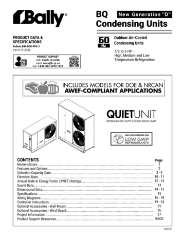
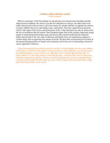
In more severe weather locations, it is recommended that theunit be elevated to allow unobstructed drainage and air flow.The following elevation minimums are recommended:Another important consideration in selecting a location for theunit(s) is the angle to obstructions. Either side adjacent thevalves can be placed toward the structure provided the sideaway from the structure maintains minimum service clearance.Corner installations are strongly discouraged.Design Temperature 15 and above-5 to 14 below -5 Suggested Minimum Elevation2 1/2"8"12"Safe Refrigerant HandlingNOTRECOMMENDEDBBBWhile these items will not cover every conceivable situation,they should serve as a useful guide.OK!OK!BWARNINGAAACOK!CAAAAAAATo avoid possible injury, explosion or death, practicesafe handling of refrigerants.AAOK!OK!OK!AAAACMinimumModel TypeR esidentialLight C ommercialRefrigerants are heavier than air. They can "push out"the oxygen in your lungs or in any enclosed space. Toavoid possible difficulty in breathing or death: Never purge refrigerant into an enclosed room orspace. By law, all refrigerants must be reclaimed. If an indoor leak is suspected, thoroughly ventilate thearea before beginning work. Liquid refrigerant can be very cold. To avoid possiblefrostbite or blindness, avoid contact and wear glovesand goggles. If liquid refrigerant does contact yourskin or eyes, seek medical help immediately. Always follow EPA regulations. Never burn refrigerant,as poisonous gas will be produced.CAirflow C learanceABC10"10"18"12"12"18"AA20"24"This unit can be located at ground floor level or on flat roofs. Atground floor level, the unit must be on a solid, level foundationthat will not shift or settle. To reduce the possibility of soundtransmission, the foundation slab should not be in contact withor be an integral part of the building foundation. Ensure thefoundation is sufficient to support the unit. A concrete slabraised above ground level provides a suitable base.WARNINGTo avoid possible explosion: Never apply flame or steam to a refrigerant cylinder.If you must heat a cylinder for faster charging,partially immerse it in warm water. Never fill a cylinder more than 80% full of liquid refrigerant. Never add anything other than R-22 to an R-22 cylinder or R-410A to an R-410A cylinder. The serviceequipment used must be listed or certified for thetype of refrigerant used. Store cylinders in a cool, dry place. Never use a cylinder as a platform or a roller.Rooftop InstallationsIf it is necessary to install this unit on a roof structure, ensurethe roof structure can support the weight and that proper consideration is given to the weather-tight integrity of the roof. Sincethe unit can vibrate during operation, sound vibration transmission should be considered when installing the unit. Vibrationabsorbing pads or springs can be installed between the condensing unit legs or frame and the roof mounting assembly toreduce noise vibration.WARNINGTo avoid possible explosion, use only returnable (notdisposable) service cylinders when removing refrigerant from a system. Ensure the cylinder is free of damage which couldlead to a leak or explosion. Ensure the hydrostatic test date does not exceed5 years. Ensure the pressure rating meets or exceeds 400lbs.When in doubt, do not use cylinder.NOTE: These units require special location consideration inareas of heavy snow accumulation and/or areas with prolongedcontinuous subfreezing temperatures. Heat pump unit baseshave cutouts under the outdoor coil that permit drainage offrost accumulation. Situate the unit to permit free unobstructeddrainage of the defrost water and ice.2
Refrigerant LinesCAUTIONThe compressor POE oil for R-410A units is extremelysusceptible to moisture absorption and could causecompressor failure. Do not leave system open to atmosphere any longer than necessary for installation.Use only refrigerant grade (dehydrated and sealed) copper tubing to connect the condensing unit with the indoor evaporator.After cutting the tubing, install plugs to keep refrigerant tubingclean and dry prior to and during installation. Tubing shouldalways be cut square keeping ends round and free from burrs.Clean the tubing to prevent contamination.Do NOT let refrigerant lines come in direct contact with plumbing, ductwork, floor joists, wall studs, floors, and walls. Whenrunning refrigerant lines through a foundation or wall, openingsshould allow for sound and vibration absorbing material to beplaced or installed between tubing and foundation. Any gapbetween foundation or wall and refrigerant lines should be filledwith a pliable silicon-based caulk, RTV or a vibration dampingmaterial. Avoid suspending refrigerant tubing from joists andstuds with rigid wire or straps that would come in contact withthe tubing. Use an insulated or suspension type hanger. Keepboth lines separate and always insulate the suction line.Insulation is necessary to prevent condensation from formingand dropping from the suction line. Armflex (or satisfactoryequivalent) with 3/8” min. wall thickness is recommended. Insevere conditions (hot, high humidity areas) 1/2” insulation maybe required. Insulation must be installed in a manner whichprotects tubing from damage and contamination.These sizes are recommended for line lengths of 79 feet orless to obtain optimum performance. For alternate line sizingoptions or runs of more than 79 feet, long line set instructionsare in the rear of this manual.Where possible, drain as much residual compressor oil fromexisting systems, lines, and traps; pay close attention to lowareas where oil may collect. NOTE: If changing refrigeranttypes, ensure the indoor coil and metering device is compatible with the type of refrigerant being used; otherwise, the indoor coil must be replaced.RECOMMENDED INTERCONNECTING TUBING (Ft)0-24Cond25-49Line Diameter (In. OD)50-79*UnitTonsSuctLiqSuctLiqSuctLiq1 1/222 1/233 3/43/47/81 1/81 1/81 1/83/83/83/83/83/83/83/83/43/47/81 1/81 1/81 1/81 1/83/83/83/83/83/83/83/8Burying Refrigerant LinesIf burying refrigerant lines can not be avoided, use the followingchecklist.1. Insulate liquid and suction lines separately.2. Enclose all underground portions of the refrigerant lines inwaterproof material (conduit or pipe) sealing the ends wheretubing enters/exits the enclosure.3. If the lines must pass under or through a concrete slab,ensure lines are adequately protected and sealed.* Lines greater than 79 feet in length or vertical elevationchanges more than 50 feet refer to the Rem ote CoolingService Manual or contact your distributor for assistance.Refrigerant Line ConnectionsIMPORTANTTo avoid overheating the service valve, TXV valve, or filterdrier while brazing, wrap the component with a wet rag, oruse a thermal heat trap compound. Be sure to follow themanufacturer’s instruction when using the heat trapcompound. Note: Remove Schrader valves from servicevalves before brazing tubes to the valves. Use a brazingalloy of 2% minimum silver content. Do not use flux.3
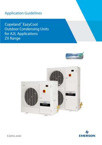
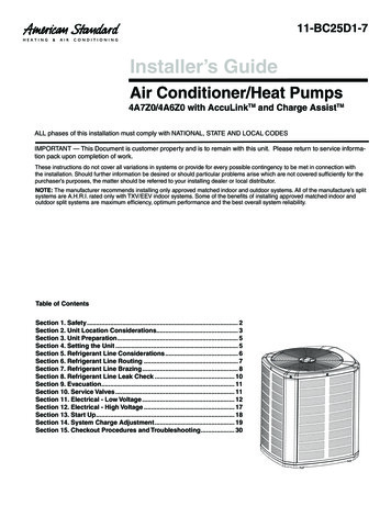
Torch heat required to braze tubes of various sizes isproportional to the size of the tube. Tubes of smaller sizerequire less heat to bring the tube to brazing temperaturebefore adding brazing alloy. Applying too much heat toany tube can melt the tube. Service personnel must usethe appropriate heat level for the size of the tube beingbrazed. Note: The use of a heat shield when brazing isrecommended to avoid burning the serial plate or the finishon the unit.Pressure test the system using dry nitrogen and soapy waterto locate leaks. If you wish to use a leak detector, charge thesystem to 10 psi using the appropriate refrigerant then usenitrogen to finish charging the system to working pressure thenapply the detector to suspect areas. If leaks are found, repairthem. After repair, repeat the pressure test. If no leaks exist,proceed to system evacuation.1. The ends of the refrigerant lines must be cut square, deburred, cleaned, and be round and free from nicks or dents.Any other condition increases the chance of a refrigerantleak.Condensing unit liquid and suction valves are closed to containthe charge within the unit. The unit is shipped with the valvestems closed and caps installed. Do not open valves untilthe system is evacuated.2.System Evacuation“Sweep” the refrigerant line with nitrogen or inert gas during brazing to prevent the formation of copper-oxide insidethe refrigerant lines. The POE oils used in R-410A applications will clean any copper-oxide present from the inside of the refrigerant lines and spread it throughout thesystem. This may cause a blockage or failure of the metering device.REFRIGERANT UNDER PRESSURE!Failure to follow proper procedures may causeproperty damage, personal injury or death.NOTE: Scroll compressors should never be used to evacuateor pump down a heat pump or air conditioning system.3. After brazing, quench the joints with water or a wet cloth toprevent overheating of the service valve.CAUTIONProlonged operation at suction pressures less than 20psig for more than 5 seconds will result in overheating ofthe scrolls and permanent damage to the scroll tips, drivebearings and internal seal.4. Ensure the filter drier paint finish is intact after brazing. Ifthe paint of the steel filter drier has been burned or chipped,repaint or treat with a rust preventative. This is especiallyimportant on suction line filter driers which are continuallywet when the unit is operating.1. Connect the vacuum pump with 250 micron capability tothe service valves.NOTE: Be careful not to kink or dent refrigerant lines. Kinkedor dented lines will cause poor performance or compressordamage.2. Evacuate the system to 250 microns or less using suctionand liquid service valves. Using both valves is necessaryas some compressors create a mechanical seal separating the sides of the system.Do NOT make final refrigerant line connection until plugs areremoved from refrigerant tubing.3. Close pump valve and hold vacuum for 10 minutes. Typically pressure will rise during this period.NOTE: Before brazing, verify indoor piston size by checkingthe piston kit chart packaged with indoor unit.Leak Testing (Nitrogen or Nitrogen-Traced)50004500VACUUM IN MICRONSWARNINGTo avoid the risk of fire or explosion, never useoxygen, high pressure air or flammable gases for leaktesting of a refrigeration NDENSIBLES OR SMALLLEAK PRESENT1500To avoid possible explosion, the line from thenitrogen cylinder must include a pressure regulatorand a pressure relief valve. The pressure relief valvemust be set to open at no more than 150 psig.1000NO LEAKSNO CONDENSIBLES5000 4123456MINUTES78910If the pressure rises to 1000 microns or less and remainssteady the system is considered leak-free; proceed tostartup.
If pressure rises above 1000 microns but holds steady below 2000 microns, moisture and/or noncondensibles maybe present or the system may have a small leak. Returnto step 2: If the same result is encountered check for leaksas previously indicated and repair as necessary then repeat evacuation.Overcurrent ProtectionIf pressure rises above 2000 microns, a leak is present.Check for leaks as previously indicated and repair as necessary then repeat evacuation.These devices have sufficient time delay to permit the motorcompressor to start and accelerate its load.The following overcurrent protection devices are approved foruse. Time delay fuses HACR type circuit breakersThree Phase Compressor RotationElectrical ConnectionsCAUTIONWARNINGUse care when handling scroll compressors. Dome temperatures could be hot.HIGH VOLTAGE!Disconnect ALL power before servicing.Multiple power sources may be present.Failure to do so may cause property damage,personal injury or death due to electric shock.Wiring must conform with NEC or CEC and alllocal codes. Undersized wires could causepoor equipment performance, equipment damageor fire.Three phase compressors are power phase dependent andcan rotate in either direction.Verify proper rotation for three phase compressors by ensuringthe suction pressure drops and discharge pressure rises whenthe compressor is energized. NOTE: When operated in reverse, a three phase scroll compressors is noisier and its current draw substantially reduced compared to marked values.WARNINGTo correct, disconnect power and switch any two leads at theunit contactor and re-observe.To avoid the risk of fire or equipment damage, usecopper conductors.High Voltage ConnectionsRoute power supply and ground wires through the high voltageport and terminate in accordance with the wiring diagram provided inside the control panel cover.NOTICEUnits with reciprocating or rotary compressors andnon-bleed TXV’s require a Hard Start Kit.Low Voltage ConnectionsThe condensing unit rating plate lists pertinent electrical datanecessary for proper electrical service and overcurrent protection. Wires should be sized to limit voltage drop to 2% (max.)from the main breaker or fuse panel to the condensing unit.Consult the NEC, CEC, and all local codes to determine thecorrect wire gauge and length.The indoor transformer must supply 24 volt AC low voltagepower to the outdoor section for the control wiring. Coolingonly units require 25VA minimum and heat pump units require40VA minimum. Low voltage wiring for two-stage units depends on the thermostat used and the number of control wiresbetween the indoor unit and the condensing unit. Route control wires through the low voltage port and terminate in accordance with the wiring diagram provided inside the control panelcover.Local codes often require a disconnect switch located near theunit; do not install the switch on the unit. Refer to the installation instructions supplied with the indoor furnace/air handler forspecific wiring connections and indoor unit configuration. Likewise, consult the instructions packaged with the thermostatfor mounting and location information.5
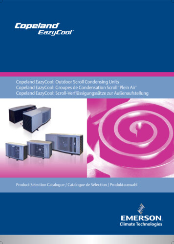
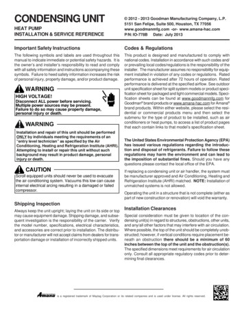
Adequate refrigerant charge for a matching evaporator and 15feet lineset is supplied with the condensing unit. If line setexceeds 15 feet in length, refrigerant should be added at .6ounces per foot of liquid line.SYSTEM COMPOSITE DIAGRAMHEAT PUMPS10 KW & BELOWTYPICAL H/PROOM THERMOSTATHEAT PUMPCW2BLUEOORANGEWHITEYYELLOWRYOCW2GR#18 GA. 7 WIREINDOOR LUEBLBL#18 GA. 5 WIRE2Open the suction service valve first! If the liquid service valve isopened first, oil from the compressor may be drawn into theindoor coil TXV, restricting refrigerant flow and affecting operation of the system.CAUTIONSEE NOTE #4POSSIBLE REFRIGERANT LEAKTo avoid a possible refrigerant leak, open the servicevalves until the top of the stem is 1/8” from the retainer.1(OPTIONAL)OUTDOOR THERMOSTATCLOSE ON TEMPERATURE FALL#18 GA. 6 WIRE NEEDED WHEN OT IS USEDSYSTEM COMPOSITE DIAGRAMHEAT PUMPSABOVE 10 KWTYPICAL H/PROOM THERMOSTATHEAT PUMPCBLUEW2WHITEOORANGEYYELLOWRYOCW2GRINDOOR UNITEREDROSEENOTE#3W1234BLBL#18 GA. 5 #2EHR1OT-1RBRY2When opening valves with retainers, open each valve only untilthe top of the stem is 1/8” from the retainer. To avoid loss ofrefrigerant, DO NOT apply pressure to the retainer. When opening valves without a retainer remove service valve cap and insert a hex wrench into the valve stem and back out the stemby turning the hex wrench counterclockwise. Open the valveuntil it contacts the rolled lip of the valve body.#18 GA. 7 WIRE(OPTIONAL)OUTDOOR THERMOSTATCLOSE ON TEMPERATURE FALLNOTES:1) OUTDOOR THERMOSTAT (OT-1) SHOULD BE THEFIRST TO CLOSE AND THE LAST TO OPEN.2) CONNECT WHITE AND BROWN WIRES FROM AIRHANDLER TOGETHER IF OT-2 IS NOT USED.3) REMOVE WIRE WHEN USING OUTDOOR THERMOSTAT4) TERMINAL BLOCK MARKINGS ARE FOR AMANAAIRHANDLERS.NOTE: These are not back-seating valves. It is not necessaryto force the stem tightly against the rolled lip.BLUEAfter the refrigerant charge has bled into the system, open theliquid service valve. The service valve cap is the secondary sealfor the valve and must be properly tightened to prevent leaks.Make sure cap is clean and apply refrigerant oil to threads andsealing surface on inside of cap. Tighten cap finger-tight andthen tighten additional 1/6 of a turn (1 wrench flat), or to thefollowing specification, to properly seat the sealing surfaces.SEE NOTE #4#18 GA. 7 WIRE NEEDED WHEN TWO OT'S ARE USEDNOMENCLATUREOT ---OUTDOOR THERMOSTAT (OPTIONAL)EHR -EMERGENCY HEAT RELAY (OPTIONAL)COLOR CODESR --REDY --YELLOWBL-BLUEBR-BROWNO --ORANGEW -WHITEG --GREEN1. 3/8” valve to 5 - 10 in-lbsThermostatwith Low Voltage Wires to Heat Pump Unit2. 5/8” valve to 5 - 20 in-lbs3. 3/4” valve to 5 - 20 in-lbsSystem Start Up4. 7/8” valve to 5 - 20 in-lbsNOTE: Units with crankcase heaters should have highvoltage power energized for 24 hours prior to start up.Do not introduce liquid refrigerant from the cylinder into thecrankcase of the compressor as this may damage thecompressor.Heat pumps are equipped with a time/temperature defrostcontrol with field selectable defrost intervals of 30, 60, or90 minutes. This setting should be adjusted at this time ifneeded. The defrost control also has SmartShift technology, which delays compressor operation at defrostinitiation and termination. If disabling this function isdesired, move the jumper from “DLY” to “NORM” on thedefrost control1. Break vacuum by fully opening liquid and suction basevalves.6
2. Set thermostat to call for cooling. Check indoor and outdoor fan operation and allow system to stabilize for 10minutes for fixed orifices and 20 minutes for expansionvalves.CAUTIONOperating the compressor with the suction valve closed willvoid the warranty and cause serious compressor damage.Charge VerificationFinal Charge AdjustmentWARNINGThe outdoor temperature must be 60 F or higher. Set the roomthermostat to COOL, fan switch to AUTO, and set the temperature control well below room temperature.REFRIGERANT UNDER PRESSURE! Do not overcharge system with refrigerant. Do not operate unit in a vacuum or at negative pressure.Failure to follow proper procedures may causeproperty damage, personal injury or death.Purge gauge lines. Connect service gauge manifold to basevalve service ports. Run the system (on low stage for twostage units) for 10 minutes to allow pressures to stabilize,then check subcooling and/or superheat as detailed in the following sections.CAUTIONSuperheat Suct. Line Temp. - Sat. Suct. Temp.Use refrigerant certified to AHRI standards. Used refrigerantmay cause compressor damage. Most portable machinescannot clean used refrigerant to meet AHRI standards.Subcooling Sat. Liquid Temp. - Liquid Line Temp.NOTICEViolation of EPA regulations may result in fines or otherpenalties.7
SATURATED SUCTION PRESSURETEMPERATURE CHARTSATURATED SUCTIONSUCTION PRESSURETEMPERATURE ºFPSIGR-410ASATURATED LIQUID PRESSURETEMPERATURE CHARTLIQUID PRESSURESATURATED LIQUIDTEMPERATURE 51605660014917060625152NOTE: SPECIFICATIONS AND PERFORMANCE DATA LISTED HEREIN ARE SUBJECT TO CHANGE WITHOUT NOTICE.8
CAUTIONTo prevent personal injury, carefully connect and disconnectmanifold gauge hoses. Escaping liquid refrigerant can causeburns. Do not vent refrigerant into the atmosphere. Recoverall refrigerant during system repair and before final unitdisposal.b.If subcooling is low and superheat is high, add chargeto raise subcooling to 7 to 9 ºF then check superheat.c.If subcooling and superheat are high, adjust TXVvalve to 7 to 9 ºF superheat, then check subcooling.d.If subcooling is high and superheat is low, adjustTXV valve to 7 to 9 ºF superheat and remove chargeto lower the subcooling to 7 to 9 ºF.Expansion Valve SystemNOTE: Do NOT adjust the charge based on suction pressureunless there is a gross undercharge.1. Temporarily install a thermometer on the liquid line at theliquid line service valve and 4-6" from the compressor onthe suction line. Ensure the thermometer makes adequatecontact and is insulated for best possible readings. Useliquid line temperature to determine sub-cooling and vaportemperature to determine superheat.NOTE: Check the Schrader ports for leaks and tighten valvecores if necessary. Install caps finger-tight.Heat Pump - Heating Cycle2. Check subcooling and superheat. Systems with TXV application should have a subcooling of 7 to 9 ºF and superheat of 7 to 9 ºF.a.The proper method of charging a heat pump in the heat modeis by weight with the additional charge adjustments for linesize, line length, and other system components. For bestresults, on outdoor units with TXVs, superheat should be 2-5 at 4-6" from the compressor. Make final charge adjustments inthe cooling cycle.If subcooling and superheat are low, adjust TXV to7 to 9 ºF superheat, then check subcooling.NOTE: To adjust superheat, turn the valve stemclockwise to increase and counter clockwise to decrease.9
Troubleshooting InformationPower FailureBlown FuseUnbalanced Power, 3PHLoose ConnectionShorted or Broken WiresOpen Fan OverloadFaulty ThermostatFaulty TransformerShorted or Open CapacitorInternal Compressor Overload OpenShorted or Grounded CompressorCompressor StuckFaulty Compressor ContactorFaulty Fan RelayOpen Control CircuitLow VoltageFaulty Evap. Fan MotorShorted or Grounded Fan MotorImproper Cooling AnticipatorShortage of RefrigerantRestricted Liquid LineOpen Element or Limit on Elec. HeaterDirty Air FilterDirty Indoor CoilNot enough air across Indoor CoilToo much air across Indoor CoilOvercharge of RefrigerantDirty Outdoor CoilNoncondensiblesRecirculation of Condensing AirInfiltration of Outdoor AirImproperly Located ThermostatAir Flow UnbalancedSystem UndersizedBroken Internal PartsBroken ValvesInefficient CompressorWrong Type Expansion ValveExpansion Device RestrictedOversized Expansion ValveUndersized Expansion ValveExpansion Valve Bulb LooseInoperative Expansion ValveLoose Hold-down BoltsFaulty Reversing ValveFaulty Defrost ControlFaulty Defrost ThermostatFlowrator Not Seating Properly Test VoltageInspect Fuse Size & TypeTest VoltageInspect Connection - TightenTest Circuits With OhmmeterTest Continuity of OverloadTest Continuity of Thermostat & WiringCheck Control Circuit with VoltmeterTest CapacitorTest Continuity of OverloadTest Motor WindingsUse Test CordTest Continuity of Coil & ContactsTest Continuity of Coil And ContactsTest Control Circuit with VoltmeterTest Voltage Repair or ReplaceTest Motor WindingsCheck Resistance of AnticipatorTest For Leaks, Add RefrigerantRemove Restriction, Replace Restricted PartTest Heater Element and Controls Inspect Filter-Clean or Replace Inspect Coil - Clean Check Blower Speed, Duct Static Press, FilterReduce Blower Speed Recover Part of Charge Inspect Coil - CleanRecover Charge, Evacuate, RechargeRemove Obstruction to Air FlowCheck Windows, Doors, Vent Fans, Etc.Relocate ThermostatReadjust Air Volume DampersRefigure Cooling LoadReplace CompressorTest Compressor EfficiencyTest Compressor Efficiency Replace ValveRemove Restriction or Replace Expansion DeviceReplace ValveReplace ValveTighten Bulb BracketCheck Valve OperationTighten Bolts Replace Valve or Solenoid Test Control Test Defrost ThermostatCheck Flowrator & Seat or Replace FlowratorHeating Cycle Only (Heat Pump) Cooling or Heating Cycle (Heat Pump) High head pressureHigh suction pressureLow head pressureLow suction pressureTest MethodRemedyUnit will not defrostUnit will not terminate defrostSystem runs - blows cold air in heatingCompressor is noisyCertain areas too cool, others too warmNot cool enough on warm daysToo cool and then too warmSystem runs continuously - little cooling/htg Compressor cycles on overload SystemOperatingPressuresUnsatisfactory Cooling/HeatingCompressor runs - goes off on overloadCondenser fan will not startEvaporator fan will not startComp. and Cond. Fan will not startDOTS IN ANALYSISGUIDE INDICATE"POSSIBLE CAUSE"Compressor will not start - fan runsPOSSIBLE CAUSESYMPTOMNo CoolingSystem will not startComplaint For detailed service information refer to the Remote Condensing Unit Service manual.NOTICEUnits with rotary or reciprocating compressors and non-bleed TXV’srequire a Hard Start Kit.10
Long Line Set Application R-410AInstallation and repair of this unit should be performedONLY by individuals meeting the requirements of an“entry level technician” as specified by the AirConditioning, Heating and Refrigeration Institute (AHRI).Attempting to install or repair this unit without suchbackground may result in product damage, personalinjury or death. Units must be installed in accordance with Regulations of the National Fire Protection Association and applicable localcodes. Where local regulations are at a variance with instructions, installer should adhere to local codes. Before connecting tubing, read this installation manual. Pay particular attention to all safety precautions.This long line set application guideline applies to all AHRI listed R-410A air conditioner and heat pump split system matchesof nominal capacity 18,000 to 60,000 Btuh. This guideline will cover installation requirements and additional accessoriesneeded for split system installations where the line set exceeds 80 feet in actual length. The long line sets in this manual areconfigured for the when outdoor unit is above the Indoor unit.This guideline is meant to provide ins
phere any longer than necessary for installation. CAUTION Use only refrigerant grade (dehydrated and sealed) copper tub-ing to connect the condensing unit with the indoor evaporator. After cutting the tubing, install plugs to keep refrigerant tubing clean and dry prior to and during installation. Tubing should