Transcription
VOI-8001VOI-8002VOI-80038-Port H.323/SIP VoIP GatewayUser Manual1Ver. 1.00-0608
Table of contentsCHAPTER 1. INTRODUCTION . 31.1 OVERVIEW . 31.2 PACKAGE CONTENTS . 31.3 KEY FEATURE . 4CHAPTER 2 GETTING STARTED . 52.1 FRONT PANEL . 52.2 REAR PANEL . 6CHAPTER 3 CONFIGURATION. 73.1 CONNECTION . 83.2 SYSTEM STATUS . 103.3 REGISTER SERVER . 113.4 VOIP CALL OUT . 12CHAPTER 4 WEB UI MANAGEMENT . 144.1 ACCESS TO WEB UI . 144.2 WEB UI MANAGEMENT . 154.2.1 Overview. 154.2.3 Register Server Setting. 544.2.4Auto Provision function . 604.2.5 Advance Setup . 624.2.6Application. 744.2.7 System. 764.2.8Route Function(/System Setup) . 854.2.9 Backup/Restore .1084.2.10Save Modification.1112
Chapter 1. Introduction1.1 OverviewThe VOI-800x series VoIP Gateway is equipped with 8 standard phone ports, one10/100BaseTX Fast Ethernet WAN port, and three 10/100BaseTX Fast EthernetLAN ports. With the integration of both voice and data, the offers ability to routedata information into network solutionVoIP Gateway has voice support that includes Quality of Service (QoS), voicecompression, echo cancellation, dynamic latency (jitter) buffers, silencesuppression, and comfort noise generation.The VoIP Gateway is compatible with xDSL and Cable-modem Broadbandservice providers with built-in support for DHCP Client, MAC Address Cloning,PPPoE and multiple auto-provisioning methods.1.2 Package Contents-8-Port VoIP GatewayCD User ManualCat.5 CablePower Adapter, 12VDC / 1.6AModel No ListVOI-8001 8-Port FXS VoIP GatewayVOI-8002 8-Port FXO VoIP GatewayVOI-8003 4FXS 4FXO VoIP Gateway3
1.3 Key FeatureVoIP Support 8 simultaneous VoIP calls Support T.38 FAX relay Support QoS(ToS) for VoIP Compliant with H.323 / SIP VoIP standard protocol Extensible by external IVR/CDR/Billing servers for value- added application Support register up to 4 Gatekeepers / Proxy servers Support worldwide off net call by ITSP service Support Multiple dialing plan / Call hunting group Adaptive Jitter Buffer function Multiple call profile for adjust VAD, Audio CODEC, H.245tunneling, DTMF In/Out band, FAX relay, Frame Size, Q.931Fast start parametersVoIP Gateway Support static and dynamic IP from DHCP, PPPoE Built-in DHCP Server Support TCP/UDP Port Mapping (Local Server Mapping) Support User-definable Static Routing Table Support Network Access Rules (LAN-to-WAN & WAN-to-LAN) Self-Protection against DoS Attacks Dynamic DNS Support WAN: 10/100Mbps RJ-45 connector, auto-sensing LAN: 3-port 10/100Mbps Ethernet Switch. (Auto MDI-II/MDI-X) VoIP: 8 port FXO/FXS ports LED Indicators : Power, Status, Ready, WAN linking , 3X LAN linking, Phone,Line Supported Protocol: UDP, TCP, Standard H.323,SIP, NAT,BOOTP, TFTP, FTP,HTTP, TELNET, IEEE 802.3/ IEEE 802.3u Selectable Coders: G.711, G.723.1, G.726, G.729A DTMF / Call progress tone detection and generation G.168 echo cancellation 1 Reset button for load factory default IP parameters setting User friendly Web configure interface Configuration/Upgrade Web and APS (Auto Provision Server) Build-in watching dog for auto recovery4
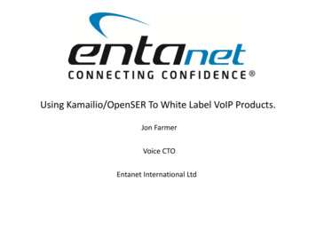
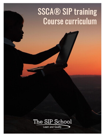
Chapter 2 Getting Started2.1 Front PanelVOI-8001VOI-8002VOI-8003(Ready) Flash: It means when the VoIP Gateway registration fail.(Ready) Constant: It means when the VoIP Gateway registration successes.(Status): This LED will flash quickly when the VoIP Gateway is eitherperforming a self test of booting up.(Power): The LED light on when power on.Note:VOI-8001 displays 1 8 Phone LED onlyVOI-8002 displays 1 8 Line LED onlyVOI-8003 displays 1 4 Line and 5 8 Phone LED only5
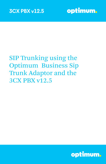
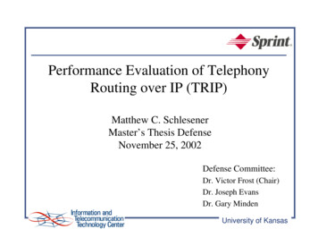
2.2 Rear PanelVOI-8001VOI-8002VOI-8003DC12V: For the included power adapter. Be sure to use only the 12VDC/1.6Apower adapter included with the product. Using the wrong power adapter candamage the product and void the warranty.Reset: Clear all settings and restore them to the initial values present whenthe device was purchased. After performing the reset, make sure to redefinethe IP settings for the device in the ‘Connection’.WAN: A 10/100 dual-speed Ethernet port fitted with an RJ-45 connectorused to connect the to WAN device (usually a DSL / Cable Modem).LAN 1 3: Three of 10/100 dual-speed Ethernet port fitted with an RJ-45connector used to connect the VoIP Gateway to a LAN device.Phone [P]: Normal RJ-11 phone jacks used to connect analog telephonesand fax machines.Line [L]: Normal RJ-11 phone jacks used to connect analog phone line orPSTN (landline)Note:Do not place heavy objects on the VoIP Gateway. Placing the VoIP Gateway in a well ventilatedarea is very important. Not doing so may cause damage to the unit.6
Chapter 3 ConfigurationThe default setting of DHCP Server inside VoIP Gateway is turn ON, So please set upyour PC TCP/IP network as “Get IP Automatically” from DHCP to get internal IP fromVoIP Gateway. By default, The VoIP Gateway will become the network gateway anddefault IP is 192.168.22.1 and will assign your PC IP as 192.168.22.X.Please go to “Control Panel” ”Network”. In the “Configure” page, choose the TCP/IP ofLAN card, and press “Properties” please choose “”Obtain IP Address AutomaticallyLaunch your browser and open the Internal UI WAP page as http://192.168.22.12The default User name is voipThe default Password is 12347
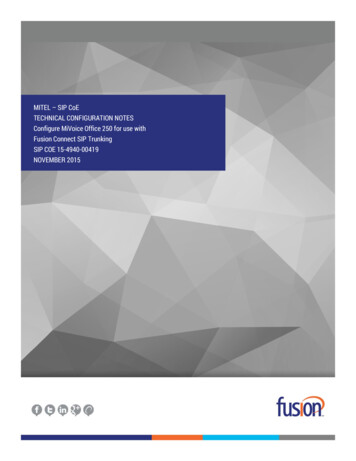
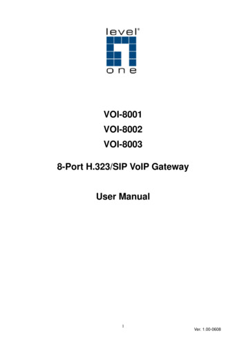
3.1 ConnectionClick “Connected Type” option below “System Setup\Wan” item:Please select the type of Internet connection you haveand set up the VoIP Gateway to use the Dynamic IPAddress, Static IP Address, PPPoE, PPTP or L2TPconnection.If your ISP has not given you an IP address, selectDynamic IP Address (default). If you have been givena specific IP address, select Specify an IP Address.To use Static-IP ADSL connection, please select “Static IP Address” and enterWAN IP settings.8
To use PPPoE ADSL connection, please select Yes in use “PPPoE” ADSLservice and enter the “username” and “password” in the PPPoE setupsection. Most of ADSL ISPs assign dynamic-IP settings to the VoIP Gatewaywhen using PPPoE. Please select Obtain IP Address Automatically(defaultsetting). You can leave the Primary and Secondary DNS IP settings in default.The VoIP Gateway automatically obtains these settings from your ISP whenthe PPPoE connection is successfully established.Please remember to setting the Primary and Secondary DNS IPs, suppliedby your ISP9
3.2 System statusThis page reveals the status of the VoIP Gateway including WAN, LAN and somehardware/firmware information.10
3.3 Register ServerIf this VoIP Gateway wants to use SIP Proxy or GateKeeper service to transferthe VoIP call, you can input the server information here. The VoIP Gateway canregister to up to four servers simultaneously.This page reveals the status of the server registration information.Here is the server configuration page, please ask the information form yourITSP.Remark: For Notify remark for this rule. Please use UNDERLINE toreplace the SPACE due to HTTP protocol limitation.11
3.4 VoIP Call OutUser key in the phone number through phone set dial pad, then VoIP Gatewaytranslate the phone number by the routing table setting here to destination IP & dialout number then Call out via network protocolRemark: For Notify remark for this rule. Please use UNDERLINE toreplace the SPACE due to HTTP protocol limitation.Area Code: Define the Prefix number fit this rule, any phone numberprefix digits matched with the rule will call out by this rule define. PleaseNotify there is a compare order rule on this routing table. That mean theVoIP Gateway will check the rule list from top to bottom one by one, any ruleitem matched with the prefix digits that user key in will go to call out directlyno regard to the rest rules below. For Example, if a rule item for area code8862 is on Index 5, another rule item for area code 886 on Index 6 belowthat will be ignored.Min Digits: The length of the dialed number should not less than thisdigits. For example, if the field is entered into ‘3’, the length of the dialnumber should be 3 digits at least.Max Digits: The length of the dialed number should not more than thisdigits. For example, if the field is entered into ‘10’, the length of the dialnumber should be 3 digits at most.a.IP Address: Define the destination IP for call out number fit this rule, usercan input below format:12
IP address, for example: 168.56.9.22 URL, route via URL. For example: www.freeworlddialip.com .This VoIPGateway can setup to register to DDNS service (/System Setup/Advanced/ Dynamic DNS/) to let user call out to another VoIPGateway with dynamic IP by URL. rsn , route via server, it will get the destination IP by server setting(/VoIP Setup/Register server/) in advance. For example: rs1 forserver 1. rs2 for server 2. rs for all the server available ( searchsequence: rs1 rs2 rs3 rs4). rs3 2 1 will try rs3 first, then rs2,then rs1.IP address, for example: 168.56.9.22All the setting above can be added by port number, for examples:168.56.9.22:8495 will call to 8495 port.Strip: the number of digits will be ignored by user input. For example, ifuser key in the number is 886212345678 and the STRIPE field is setting to4, the first 4 digits 8862 will be truncated and actually call out number willbe 12345678.Prefix: The numbers will be added on the prefix of user key in number.For examples, if user key in the number is 12345678 and the PREFIX field issetting to 0028862, the actually call out number will be 002886212345678.Another example, if user key in the number is 90, STRIP field is setting to 2,and the PREFIX field is setting to 0,12345678, the actually call out numberwill be 0,12345678 ( , mean wait 1 second). This example is especially forspeed dial function.To add new rule item on routing table, please assign the item number you want toinsert before, input AREA CODE and IP address then press ADD button to add it onthe list. Then modify the necessary information on the routing table list.Please remember to press the modify button to take it effect. For store back to flashmemory, please press “Save Modification”.13
Chapter 4 Web UI Management4.1 Access to Web UIThe VoIP Gateway provide user friendly Web interface to let you configure your VoIPGateway functionThe default setting of DHCP Server inside VoIP Gateway is turn ON, So please set upyour PC TCP/IP network as “Get IP Automatically” from DHCP to get internal IP fromVoIP Gateway. By default, The VoIP Gateway will become the network gateway anddefault IP is 192.168.22.1 and will assign your PC IP as 192.168.22.X.Please go to “Control Panel” ”Network”. In the “Configure” page, choose the TCP/IP ofLAN card, and press “Properties” please choose “Obtain IP Address Automatically”Launch your browser and open the VoIP Gateway Internal UI WAP page ashttp://192.168.22.1The default User name is voipThe default Password is 123414
4.2 Web UI ManagementThe VoIP Gateway provide user friendly Web interface to let you configure your VoIPGateway function and VoIP function. There are a help on line content within eachsetting page. Please press Help hyperlink to view the on line help. There are 3 mainfunctions for web, VoIP, System Setup (VoIP Gateway) & System maintenance. Eachfunction is setup by the function below:4.2.1 OverviewRoute functionzConnection (Setting WAN connecting)zLAN SettingzFirewall Basic setupzNetworks System Status DisplayzDynamic DNS SettingzDHCP Server SettingzStatic Routing SettingzLocal Server SettingzDMZ SettingVoIP functionzPort Status DisplayzLine Configure SettingzLine SettingzTone SettingzVoIP Call Out Routing Table SettingzVoIP Call In Routing Table SettingzVoIP Call In IVRzVoIP Routing Profile SettingzVoIP Forwarding Profile SettingzAuthorizationzRegister Status15
System Maintenance functionzConfigurations Backup/RestorezVoIP Module Backup/RestorezReboot SystemzSave ModificationGateway Manual overview16
4.2.2 VoIP Function4.4.2.1 VoIP Setup/ Port Status/This page will display the current and last time VoIP call status & result.a.The PC time : will show the date & time that your connected PC now.b.The VoIP Gateway time : will show the date & time on this VoIP Gateway,the date& time may get from SNTP server or setting from your PC. You mayset the SNTP server from /System Setup/Administrator/Date & Time/.A. Ports Messagea.Port: display the port number, e.g. 1 or 2.b.Type: Telephone interface type: FXO: (DAA interface) for connect to telephone line or PBX extensionline. FXS: (SLIC interface) for connect to regulate phone set.c.Display Name: display the remote party name of this VoIP call.d.Status: Current status of this port. Idle: Standby for make a phone call. Signal: Waiting for DTMF press or VoIP protocol connecting. In: There is a phone call made from phone port and call out to Networkby VoIP.17
Out: There is a phone call made from Network VoIP and pick up byphone set.e.Connected IP: The remotely party IP of this VoIP call.f.Caller ID: Caller ID received from telephone line port.g.Start Time: Date & time of this VoIP call begin on this port.h.End Time: Date & Time of last VoIP call End on this port.i.Talking Sec: Total talked seconds of last VoIP call on this port.j.Dialed number: On the VoIP call out (line status display “In”). This will display the realdial out number for VoIP call. On the VoIP call in (line status display “Out”). This will display thenumber will dial out to phone line. Release by: This will display the reason of this call termination.B.Error MessageFor some reason,(ex. All lines of this VoIP Gateway are busy) here will displaythe failure information about the last failure VoIP Call.18
4.2.2.2VoIP/Line Configure/ Line Setting/VoIP Setup/Line Configure/Line Setting/This page will setup the phone line information each port.a.Port: display the port number, e.g. 1 or 2.b.Interface: Telephone interface type:a. FXO: for connect to telephone line or PBX extension line. FXS: for connect to regulate phone setName: Line name for this port. This will send and display on the remoteside during VoIP callb.Line number: Telephone number assigned to this line.c.TxGain: Transmitter Gain. This will adjust the speaker volume of localphone set. The adjust range is from 3 to -13dB. Higher value will causelouder sound come from local phone set.d.RxGain: Receiver Gain. This will adjust the microphone volume of localphone set. The adjust range is from -3 to 13dB. Higher value will increaseamplifier the sound get from local phone set.e.Inbound: Enable or disable the VoIP call to Internet. Disable the inboundoption will not allow any call made from phone set to Internet.f.Outbound: Enable or disable the VoIP call from Internet. Disable theOutbound option will not allow any call made from Internet to phone set.g.Hotline: When Enable, it will allow you to make a VoIP call without Pressany number. That mean it will direct call out by VoIP when you off hook thephone of this line.For example, if you want line 1 to become a hot line for VoIP call, every time19
when you off hook the phone connected to the line 1, it will directly call toanother VoIP gateway location at 168.56.09.22 and dial 601. You can enable theline 1 as hot line, and add a routing rule on the routing table on /VoIPSetup/Routing Setup/VoIP Call Out/ to assign the AREA CODE to hl1tohandle the VoIP Gateway rule for hot line function. And please also remember toStrip 3 digits to stripe the “hl1” symbol and remember add real phone numberyou want to dial on Prefix. In this case, the setting example on call out routing(/VoIP Setup/Routing Setup/VoIP Call Out/) for hot line application is asbelow:IndexRemarkArea CodeIP AddressStripPrefix1Hot Line CallHl110.1.1.1360120ProfileDeleteDelete2
4.2.2.3Line configure/ Tone Setting/VoIP Setup/Line Configure/ Tone SettingA.Call Progress ToneThis page defines the tones generated to the phone connected to the phone port.The cadence of CPT is been defined here also. All lines use same toneparameters. After modify the tone parameters, you must save modify then2Reboot to let the modified parameters work.2zDetect Voice Busy Cycle: Use the parameters to automatic detect cadencebusy tone. When detected a voice cadence repeat over the number settingin sequence, the VoIP Gateway will treat it like busy tone and disconnectautomatically. Please do not set this parameter less than 5 to avoidunexpected erroneous disconnect.B.Tone define TableYou can set up to 15 tones set for generation. For the generation, the first entrywill be used. The call progress tones, ranging from 300 Hz to 2000 Hz. Tone:Maximum 15 tones can be defined.a.Type: Dial: Define the generated dial tone.21
Busy: Define the busy tone for generate. Ring: Define the ring back tone for generateb.Low freq: Lower frequency for defined tonec.High freq: Higher frequency for defined tone. Each tone can define twofrequencies, if only one frequency needed, please leave High Frequency to0.d.T ON 1, T OFF 1, T ON 2, T OFF 2: The cadence pattern of up to four intervals for each dual-frequency.Minimum Cadence value is 30msec.22
4.2.2.4Line configure/ Line Feature/VoIP Setup/Line Configure/ Line FeatureThis page defines the feature on the phone port of the VoIP Gateway.A. Dial Pause signal length(as ,)[100 3000] ms:Define the pause time (ms) of the “,” on the /Routing Setting/VoIP CallOut/. This pause time is usually for time delay when connect to PBX andused for seize the CO line. The default pause time is 1000ms. The inputrange is between 100 to 3000 ms. User can use more then one “,” to getlonger delay time.B. Loop Current Drop & Polarity Reversal Generate:Define the signal generated on local side when remote side disconnects:z Disable: Disable the Loop current Drop and Polarity ReversalGenerate signal, only generate busy tone.z Polarity Reversal- Enable: Enable FXS interface to generate thePolarity Reversal Signal.z Current Drop- 1 S: Enable FXS interface to generate one secondCurrent Drop signal.z Current Drop- 2 S: Enable FXS interface to generate two secondsCurrent Drop signal.23
zCurrent Drop- 3 S: Enable FXS interface to generate three secondsCurrent Drop signal.C. Called Number Relay on FXS :Define when use the FXS interface to outbound call, resend or Drop out thedialed number. Drop out: Do not send the dialed number. When use the FXS portdirect connect to phone set for outbound call, please enable the“Drop out” function to avoid hear the unnecessary dialed numberwhen answer the phone call. Resend: Resend the dialed number. When use the FXS port toconnect to PBX line for outbound call, please enable the “Resend”function to redial the destination number by DTMF, this will cause thePBX transfer to the call to the final user.D. Caller ID Generate type:Define the Caller ID (CID) signal generate format:Disable: Disable, do not send CID signal. DTMF: Send CID signal by DTMF format. FSK Bell: Send CID signal by FSK Bell format. FSK ETSI: Send CID signal by FSK ETSI format. E.Caller ID Detect Mode:Define the CID detect format of FXO interface: Disable: Disable, Do not detect any CID signal DTMF: Enable detect CID signal by DTMF format. FSK Bell: Enable detect CID signal by FSK Bell: format. FSK ETSI: Enable detect CID signal by FSK ETSI: format.F.When VoIP call out, send ANI by:Define when VoIP call out, use the below number as the Caller ID (ANI): Register Number: Use the gateway register number as ANI.Line Number: Use the line number setting on the /VoIPSetup/Line Configure/Line Setting/ as ANI. PSTN CID: Use the received Caller ID number from PSTN line asANI.G. FXS Ring Method:Define how the FXS interface to ring the phone line when VoIP call in: Free Random: Any unused available line.24
Line number Priority: The 1st line has high priority; it will always ringthe 1st line if it is available. When 1st line is busy, it will try to ring 2ndline if it is free.Rotation: 1st line ring first, then 2nd line ring next time, when thelatest line ring this time, it will come back to ring 1st line next time.All: Ring all phone lines if it is available.Sequence: Ring all the available phone line one by one, the ringperiod for ring each phone is definable.Period (sec.): define the ring period (seconds) when select“Sequence” ring.25
4.2.2.5Line configure/ Line Polarity/VoIP Setup/Line Configure/ Line PolarityThis page defines the Polarity on the phone port of the VoIP Gateway.If use the normal phone set to connect gateway, please select “Normal”.If use PBX or special PSTN line (support polarity invert), then please select“Invert”.Please remember to press the Modify button to take it effect. For store back to flashmemory, please press Save Modification (/System Maintenance/SaveModification/).26
4.2.2.6Routing Setup/ VoIP Call Out Setting/VoIP Setup/Routing Setup/VoIP Call OutThis page let you define the routing rule for Call out to VoIP. (User press thephone number through phone set dial pad, then VoIP Gateway translate thephone number by the routing table setting here to destination IP & dial outnumber then Call out via network protocol).Here can define some specialkeyword like IPIVR, PSTN as destination for some special function also.Each time when you off hook the phone connected to this VoIP Gateway, you willhear a dial tone or prompt voice to remind you to press the phone number, afteryou input the number you called, if digits of the number of you called is notexceed the Max Digits, please remember to press the # key for ending the input,if you do not press # key for enter, gateway will automatically call out thenumber after timeout of define on OtherDigitTime.A. Time & Digits wait for dial outThe VoIP Gateway wait user input the number digits & time parameters asbelow:Time & Digits wait for user Press.a.MaxDigits: Define the maximum digits wait for user press for all VoIP CallOut, if user press digits match the number defined here. It will go to27
translate for call out rule without needed to press # key.b.FirstDigitTime: Define the waiting time (seconds) for user press phonenumber first digit. User need to press first digits before the setting time(seconds) defined here, if VoIP Gateway wait for the defined seconds andthere is no any digits press, the VoIP Gateway will stop to wait and feedbackthe user busy tone.c.OtherDigitTime: Define the waiting time (seconds) for user press phonenumber secondary & the rest digits. User need to press the rest digitsbefore theseconds defined here, if VoIP Gateway wait for the definedseconds and there is no any digits press, it will go to translate for call outrule without needed to press # key.d.Timeout for Re-entry route: When one of the rules on the VoIP call outrules is matched and be execute, the device will wait the time( seconds)defined here for successful connection, but if time out defined there stillfailure connection, it will trying to reroute by another call rule setting by the“v” the number prefix.For example as below, when the user try to call the destination number12345678, it will try to call the gateway location at 168.11.22.33, but if wait10 seconds and still can not successful connection, the gateway will abortthe call and try call out by the PSTN line.Timeout for Re-entry route:Index Remark1210Area MinMaxDestinationCode Digits DigitsNormal8ruleBackupv8rule88second.Strip Prefix Profile Delete168.11.22.33DeletePSTN2Delete2 The example that use “v” prefixes for reroute the call out When user enable the hot line function on /VoIP Setup/Line Configure/Line3Setting/ menu, it will over ride the above parameters and direct call out by hotline call out rule.B.VoIP call out Routing Table28
b.Remark:Remark for this routing rule. Please use UNDERLINE to replacethe SPACE due to HTTP protocol limitation.c.Area Code: Define the Prefix number fit this rule, any phone number prefixdigits matched with the rule will call out by this rule define. Please Notifythere is a compare order rule on this routing table. That mean the VoIPGateway will check the rule list from top to bottom one by one, any ruleitem matched with the prefix digits that user press will go to call out directlyno regard to the rest rules below.For Example, if a rule item for area code8862 is on Index 5, another rule item for area code 886 on Index 6 belowthat will be ignored.By setting the hln (hl1 for hot line one, hl2 for hot line two) on the area codefield and enable hot line function (/VoIP Setup/Line Configure/LineSetting/), the VoIP Gateway can service the hot line direct call.d.Min Digits: define the minimum digits wait for user press for number fitthis rule, if user press digits less the number defined here. It will keepwaiting for input until exceed the FirstDigitTime defined time. If userpress digits more then Min Digits here, the VoIP Gateway will wait timedefined on OtherDigitTime then go to translate for call out rule withoutneeded to press # key.e.Max Digits: define the maximum digits wait for user press for number fitthis rule, if user press digits match the number defined here. It will go totranslate for call out rule without needed to press # key.f.Destination: Define the destination IP for call out number fit this rule, usercan input below format: IP address, for example: 168.56.9.221.2.for sip Æ please add sip: before ip address, for example sip:168.56.9.22for h323 Æ please add h323: before ip address , for exampleh323:168.56.9.22 URL, route via URL. For example: sip.fwd.com .This VoIP Gateway ced/Dynamic DNS/) to let user call out to another VoIPGateway with dynamic IP by URL. gkn : route via gatekeeper, it will get the destination IP by gatekeepersetting (/VoIP Setup/Gatekeeper/) in advance. For example: gk129
for gatekeeper 1. gk2 for gatekeeper 2. gk for all the gatekeepersavailable ( search sequence: gk1 gk2 gk3 gk4). Gk3 2 1 will trygk3 first, then gk2, then gk1.All the setting above can be added by port number, for examples:168.56.9.22:8495 will call to 8495 port.f. srn, rsn:server.same as gkn , basically, it is used for SIP register PSTN: route this call via PSTN line interface. This is usually usedfor the backup route for the rule setting on /Routing setup /VoIPCall out/ with “v” prefix. ipivr: Enter the Network parameter voice interactive settingmode. User can use this function to enter all the WAN networkparameters without PC. ( Please refer the application note “ IPIVR produce “ for more detail procedure ). ldcfg: Restore all parameters to the default values. User canassign a password to use this function to restore all theparameters to the default values. rect: Enter to voice record procedure . User can assign a functioncode for enter the voice record procedure, when press this codeto enter the voice record procedure, the device will record 30seconds voice file and keep on sound wave file ( G.711, uLaw),User can download the recorded wave file on /VoIPSetup/Advance setting/Prompt Voice/ and used this file toupload for customization voice file or used for busy tone analysis. agent: agent code setting. When a VoIP call in made by thisdevice, it will ring the assigned phone set. If the user want to usethe different phone set (connected to same device, but did notring) to answer the call, just off hook and enter this agent code toredirect the call to this phone you used for talk. lo: assign the route to local loop back. The destination IP of thiscall will be the local host, i.e.:127.0.0.1Strip: the number of digits will be ignored by user input. For example, if30
user press the number is 886212345678 and the STRIP field is setting to4, the first 4 digits 8862 will be truncated and actually call out number willbe 12345678.g.Prefix: The numbers will be added on the prefix of the user press number.For examples, if user press the number is 12345678 and the PREFIX llbe002886212345678. Another example, if user press the number is 90,STRIP field is setting to 2, and the PREFIX field is
The VoIP Gateway is compatible with xDSL and Cable-modem Broadband service providers with built-in support for DHCP Client, MAC Address Cloning, PPPoE and multiple auto-provisioning methods. 1.2 Package Contents - 8-Port VoIP Gateway - CD User Manual - Cat.5 Cable - Power Adapter, 12VDC / 1.6A Model No List VOI-8001 8-Port FXS VoIP Gateway