Transcription
Performance Evaluation of TelephonyRouting over IP (TRIP)Matthew C. SchlesenerMaster’s Thesis DefenseNovember 25, 2002Defense Committee:Dr. Victor Frost (Chair)Dr. Joseph EvansDr. Gary MindenUniversity of Kansas
Presentation Organization Introduction Background TRIP Research Issues TRIP Model Description TRIP Simulation Results & Conclusions Summary of Conclusions Next Steps Acknowledgements Questions2University of Kansas
Introduction Telephony Routing over IP (TRIP) is new signaling protocolbeing developed for use in an IP network. The most basic function of TRIP is to locate the optimumgateway out of a Voice over IP (VoIP) network into thePublic Switched Telephone Network (PSTN). Thesis investigation will center on the impact of varyingphysical characteristics of a TRIP-enabled system such astraffic load and network topologies via changes inpropagation delay.3University of Kansas
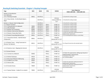
Background Control Signaling: Exchange of messages related to call setup, monitoring, teardown,and network management information. Provides command and control infrastructure for communicationsnetworks. Signaling System 7 Predominant control signaling network for PSTN. Signaling Point: use signaling to transmit and receive controlinformation . Signaling Link: interconnect signaling points. Signaling Transfer Point: transfer signaling messages from one link toanother. Signaling Control Point: database for SS7 network.4University of Kansas
Background SS7 NetworkUser BUser AUser C Figure from: International Engineering Consortium,http://www.iec.org/online/tutorials/ip in/topic01.html, 20025University of Kansas
Background Signal Transport (SigTran) Developed to allow VoIP networks to utilize the extensivefunctionality and superior performance of SS7. Interworks VoIP network with SS7/PSTN SS7 packets are encapsulated in IP packets by Signaling GWand sent to Media GW Controller which makes routingdecisions. Media stream (voice) is encapsulated in IP packets by MediaGW.6University of Kansas
Background Resource ReSerVation Protocol (RSVP) Designed to provide integrated services across the Internet. Host requests service with very specific connection parameters fromthe network. Network routers along the specified path will each be requested fordedicated resources (e.g., bandwidth). If all nodes along the path dedicate the resources, the reservation iscomplete and the host may begin use.RVSP RequestRVSP RequestRVSP RequestRVSP Request7University of Kansas
Background Voice over IP (VoIP) A network that transmits voice packets over IP. Voice signal is digitized, compressed and converted to IPpackets. Specialized signaling protocols are used to set up and teardown calls, carry information required to locate users andnegotiate capabilities. Examples are H.323 and SIP.8University of Kansas
Background Session Initiation Protocol (SIP) VoIP signaling protocol.Begins, changes and terminates network sessions.Provides advanced signaling and control to an IP network.User Agent: end users of the SIP network that initiate requests and arethe destination of services offered across the SIP network.Registrar: manage user agents assigned to their network domain.Proxy Server: forward SIP requests and responses.Redirect Server: take SIP requests and return location information ofanother user agent or server.Location Server: locates the next-hop for an incoming session request.Also, media GW and signaling GW for interworking with PSTN.9University of Kansas
BackgroundProxy/Registrar/Redirect ServicesLocation Server SIP NetworkSignaling/Media GWSignaling/Media GWSIPSIPIPIPPRISIPPRIPST N/SS7IP NetworkSIPIPIPENTERPRISE IPNETW ORK123456789*8#User A123456789*8#SIPIPSIPSoft PhoneUser AgentSIP PhoneUser AgentDashed Lines areSignaling links10University of Kansas
TRIP The most basic function of TRIP is to locate the optimumgateway out of a Voice over IP (VoIP) network into thePublic Switched Telephone Network (PSTN). TRIP is a voice routing protocol that is independent of theunderlying VoIP signaling protocol. Common TRIP implementations use either SIP or H.323. Benefits of a TRIP-enabled Network Reachable routes must be manually provisioned in the GW only. Location server has knowledge of dynamic state of gatewayresources. Dynamic routing which provides the optimum path for sessionrouting.11University of Kansas
Location Server (LS) Exchanges route table information with other locationservers. TRIP builds a routing table for the LS it supports. The LS will utilize that routing table to make session requestforwarding decisions. Call requests can be rerouted between location servers basedon dynamic state of gateway resources. A location server running TRIP is referred to as a TRIPspeaker.12University of Kansas
TRIP-lite (TRIP-GW) TRIP-lite advertises routeand prefix destinations to atleast one location server. Attributes advertisedinclude destinationprefixes, capacity to eachprefix destination, dynamicutilization of each trunkgroup. TRIP-lite allows the LS tohave real-time knowledgeof available GW resources.S IP P r o x yLST R IP - l i t eM e s s a g in gL iteL iteL iteGW1GW3PRIGW2PRIP r e f ix 9 1 3PRIP r e f ix 9 1 3 & 8 1 6P S T N /S S 713University of Kansas
I-TRIP Interior AdministrativeDomain Routing (I-TRIP) I-TRIP exchanges GWlocation and routinginformation insidethe locallyadministered domain(ITAD). I-TRIP database updatemessaging is flooded to allLS’s throughout the ITAD,based on OSPF.ITADSIP ProxySIP ProxyLSLST RIP UpdateFloodingT RIP-liteMessagingLiteT RIP-liteMessagingSIP y of Kansas
E-TRIP Exterior Administrative Domain Routing (E-TRIP) E-TRIP exchanges telephony routing informationbetween administrative domains.ITAD AITAD B Based onBGP.E-T RIPT RIP-litem essagingSIP ProxySIP ProxySIP ProxyLSLSI-T RIPLSI-T RIPLiteLiteSIP ProxyT RIP-litem essagingLiteLSLitePRIPRIPSTN15University of Kansas
TRIP Research Issues What is the impact of LS-to-GW and LS-to-LS propagationdelay on blocking probability in a TRIP environment? The importance of this issue to a carrier concerns deployment oflocation servers to support the network. Determining propagationdelay impact on call blocking will allow designers to place the fewestnumber of LS to support demand in a given geographic area. What is the impact of LS-to-GW and LS-to-LS delay on callrequest delivery in a TRIP environment? The importance of this issue to a carrier concerns quality of serviceprovided to customers. Determining where delay will be incurred willallow designers to meet delay budget.16University of Kansas
TRIP Research Issues What is the impact of LS-to-GW and LS-to-LS delay onlocation server call request rerouting in a TRIP environment? The importance of this issue to a carrier concerns call setup.Determining the impact of call reroutes on call setup delay impactsthe delay budget. What is the impact of traffic intensity along with LS-to-GWand LS-to-LS delay variation in a TRIP environment? The importance of this issue to a carrier is to understand how thenetwork will react under varying load conditions. A network designerwould be able to design the network to a specific load.17University of Kansas
TRIP Research Issues What is the impact of trunk failure along with LS-toGW delay and LS-to-LS delay variation on blockingprobability in a TRIP environment? The importance to a carrier is to understand how a failure will impactcustomers. How does the system blocking performance of aTRIP network differ from the blocking performanceof a SIP network? The importance to a carrier is to understand how the addition of TRIPwill affect a SIP network. The addition of TRIP will add complexityand cost over a SIP network. This experiment will show the benefits.18University of Kansas
TRIP Model TRIP research questions to be addressed throughsimulation. Model developed to evaluate each research issue. Model developed using Extend graphical modelingsoftware. Model will simulate appropriate number of events(call requests) to provide a 99% confidence interval.19University of Kansas
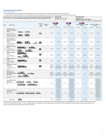
TRIP Model Description TRIP Model Architecture: Two Location Server & Gateway PairsEach LS/GW pair has a dedicated call request generatorLS1 only sends calls to GW1 and LS2 only sends calls to GW2GW1 has 48 DS-0 to destination prefixGW2 has 24 DS-0 to destination prefixEach LS is running TRIPEach GW is running the TRIP-lite ClientTRIP-lite messaging is sent only when GW is at full trunk utilization.This is the worst case-scenario. Varying network topology via element-to-element propagation delay.20University of Kansas
TRIP Model DescriptionLS-to-GW DelayTRIP-lite UpdateMessagingLS1LSLiteLS1 Call Generator12 3475 68 9*8 #GeneratesVariableTrafficLoad which varies CallBlockingLS-to-GW DelayGW148 Trunks to PSTNLS to LS CallRequest ReroutingPSTN/SS7LS-to-LS DelayLS-to-LS DelayLite24 Trunks to PSTNGW2LSLS2 Call Generator1 234 567 898#*Generates TrafficLoad of 1% CallBlockingLS2LS-to-GW DelayTRIP-lite UpdateMessagingLS-to-GW Delay21University of Kansas
TRIP Model Description Variable SystemParameters LS-to-GW Propagation DelayLS-to-LS Propagation DelayTraffic LoadGateway Trunk Failure System PerformanceMetrics Overall System Call BlockingLS Call BlockingGW Call BlockingCall Request Delivery DelayPercentage Call RequestRerouting between LocationServers Cumulative Blocked Callsduring Gateway Trunk Failure22University of Kansas
TRIP Simulation Results System Parameters: Varied traffic loads ranging from 1% to 85% callblocking. LS-to-GW and LS-to-LS propagation delay was varied. Delay values included: 0ms: elements co-located 24ms: cross country fiber connection 250ms: satellite link. GW trunk failure.23University of Kansas
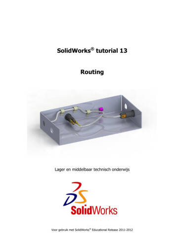
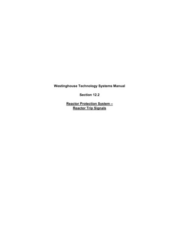
TRIP Simulation Results Impact of propagation delay and load variation on Call Blocking. Results for system call blocking vs. time, 5% call blocking, LS-to-GWdelay variation, Blue: 0ms; Red: 24ms; Green: 250ms.ValuePlotter, DE .4495514.7778314.1061113.4343912.76267Steady State tends to Erlang BPrediction of 5% Call 7197-2.3315e-15-33.86005Product 02468.962Product 14971.7837474.605Product .5324994.3627497.1830000Product 324University of Kansas
TRIP Simulation Results System call blocking is driven by traffic load. System call blocking follows Erlang B prediction. Propagation delay and thus network topology does not impact system callblocking performance.System Call Blocking %LS to GW Delay900msBlocking raffic Intensity (Erlang)478.80250msErlang B25University of Kansas
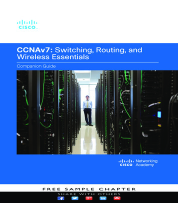
TRIP Simulation Results For low LS-to-GW delay, LS call blocking follows Erlang B predictions. For high delay (satellite link), blocking shifts from LS to GW.LS Call Blocking %LS to GW 6579.55108.05 204.15 478.80Traffic Intensity (Erlang)Blocking (%)Blocking (%)160ms90GWCall Blocking %LS to ms0250ms24.01ms57.9566.6579.55108.05 204.15 478.80Traffic Intensity (Erlang) LS-to-LS delay variation does not cause blocking shift from LS to GW.26University of Kansas
TRIP Simulation ResultsImpact of propagation delay and load variation on call request rerouting.Call request rerouting is driven by traffic load.The higher the traffic load the great percentage of reroutes.Propagation delay and thus network topology does not impact thepercentage of call request reroutes.Percent Call Request RerouteLS to GW Delay40Reroute % 01ms5125ms057.9566.6579.55108.05 204.15 478.80Traffic Intensity (Erlang)250ms0ms353.43ms30Percent Call Request RerouteLS to LS Delay400msReroute % (%) 24.01ms5125ms057.9566.6579.55108.05 204.15 478.80250msTraffic Intensity (Erlang)27University of Kansas
TRIP Simulation Results Impact of propagation delay and load variation on Call Request Deliveryto a GW. LS-to-GW propagation delay will add directly to the call delivery delay. The percentage of LS-to-LS delay added to total call delivery delay isbased on traffic load and call request rerouting. Overall call delivery delay is the sum of both.Call Request Delivery DelayLS to GW 5ms10020.58ms5024.01ms125ms057.9566.6579.55108.05 204.15 478.80Traffic Intensity (Erlang)250msCall Request DeliveryDelay (ms)Call Request DeliveryDelay (ms)300Call Request Delivery DelayLS to LS 5 204.15 478.80Traffic Intensity (Erlang)28University of Kansas
TRIP Simulation Results The relationship between call request rerouting and LS-to-LSdelay can be illustrated by this predictive expression. At 24ms LS-to-LS propagation delay there are 4.3% calls reroutedand incur both the 24ms LS-to-LS delay plus the constant 4ms LS-toGW delay. Subsequently, 95.7% of call requests do not get rerouted and onlyincur the 4ms LS-to-GW delay. Call Delivery Delay 0.043*[24ms 4ms] 0.957*[4ms] 5.032ms The predicted value through simulation is 5.634ms. Thus the deliverydelay can be predicted given the simulated call request reroutepercentage.29University of Kansas
TRIP Simulation ResultsBlocking (%) Comparison of a TRIP-enabled Network to a SIP Network. SIP call blocking is consistently higher than TRIP. Given standard traffic assumptions Erlang B cannot be used to predict callblocking in a SIP network.System Call Blocking %LS to GW 55108.05 204.15 478.80Traffic Intensity (Erlang)SIPErlang B30University of Kansas
TRIP Model Demonstration Demonstration of TRIP model simulating trunk failure onGW1. 1% call blocking prior to failure. At 50,000 seconds, GW1 suffers a T1 failure. This drops theavailable trunks on GW1 from 48 to 24. Overall systemresources drop from 72 DS-0 to 48. After failure, Erlang B predicts blocking of 22.1%. At 125,000 seconds, restoral of failed trunk and 1% callblocking. At 200,000 seconds, simulation ends.31University of Kansas
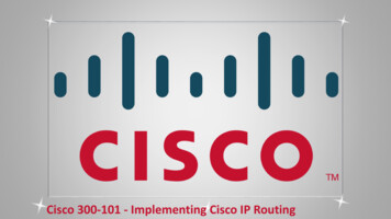
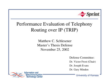
TRIP Simulation Results Gateway trunk failure results Cumulative number of blocked calls versus time.ValuePlotter, DE 173.255021.125Blocked ed 01250025000NumberExited 137500NumberExited 50000162500175000187500200000NumberExited 3time (seconds)32University of Kansas
TRIP Simulation Results TRIP results during trunk failure with varied propagation delay.DelayLocationDelay(ms)IntervalAverage Slope(blocked/sec)CalculatedCall Blocking(%)Erlang GW0msAfter Failure0.0701321.8%22.1%LS-to-GW0msAfter 003311.03%1.0%LS-to-GW24msAfter Failure0.0718122.3%22.1%LS-to-GW24msAfter 0.003521.09%1.0%LS-to-GW250msAfter Failure0.0721722.4%22.1%LS-to-GW250msAfter Restoral0.003271.02%1.0% LS-to-LS results also show propagation delay has no impact.33University of Kansas
TRIP Simulation Results System reaction to a state change is dependent on trafficload. As the traffic load is increased, the system reaction timeto the state change will decrease. For a 1% call blocking, the TRIP system will react to thestate change in approximately 3.1-9.3 second. 15% in 2.3-6.9 second & 85% in 0.38-1.14 second. Propagation delay during a failure scenario does notimpact the system reaction to new state.34University of Kansas
TRIP Conclusions Network topology does not impact system blockingprobability. In a TRIP-enabled network, the system blockingwill be driven by traffic load. This result impacts geographic deployment of location servers tosupport the network. From a system blocking standpoint, designersdo not need to be concerned with propagation delay but must beconcerned with traffic load. Overall system blocking will follow Erlang B given specifiedvalues for traffic load and call holding time. This result allows designers to implement a correctly sized TRIPnetwork based on forecasted customer usage. This would impactnumber of trunks to support a given destination prefix, number ofgateways in a geographic area, and number location servers in thenetwork.35University of Kansas
TRIP Conclusions As LS-to-GW delay is increased towards a satellite link delay(250ms), loss of knowledge about the current state of thesystem causes call blocking to increase at the GW. This result places a limit on implementation options. TRIP messagingcan incur propagation delay equivalent to cross country fiber links butsatellite links should not be considered. Propagation delay, LS-to-GW and LS-to-LS, does not impactthe percentage of reroutes in the system. The traffic intensityis the driving factor. This result dictates that designers be concerned with traffic load andnot propagation delay when addressing TRIP rerouting functionality.36University of Kansas
TRIP Conclusions LS-to-GW propagation delay will add directly to the calldelivery delay. For LS-to-LS delay only a percentage of thepropagation delay will add into the total call delivery delay.And that amount will be dependent upon the traffic load. This issue impacts the delay budget. The result indicates that any delaybetween the LS and GW must be added to overall call setup delay. While,only a percentage of the delay between LS and LS should be added. SIP blocking is consistently higher than TRIP and higherthan what would be predicted by Erlang B. TRIP provides a SIP network with lower blocking. It benefits the carrier withless provisioning, gateway dynamic resource information available at theproxy, optimum path routing, and also better blocking performance.37University of Kansas
TRIP Conclusions The time required for a TRIP system to react to a change instate (i.e., gateway trunk failure) is based on traffic load. Asthe traffic load is increased, the system reaction time to thestate change will decrease. Additionally, the results showthat propagation delay during a failure scenario does notimpact the system reaction to new state. When a failure happens the TRIP network will react within areasonable time interval and tend toward the new steady state.38University of Kansas
Next Steps Simulation of TRIP-lite network with added updatemessaging. Simulation of TRIP network synchronization (TRIP RoutingConvergence). Lab evaluation of Vendor TRIP-lite equipment and software. Lab evaluation of Vendor Interior Administrative DomainRouting (I-TRIP) equipment and software. Lab evaluation of Vendor Exterior Administrative DomainRouting (E-TRIP) equipment and software. Lab evaluation of a TRIP network with all TRIP entities.39University of Kansas
Acknowledgements Special Thanks to: Dr. Victor Frost Dr. Joseph Evans Dr. Gary Minden The Cisco TRIP Marketing and DevelopmentTeam And Very Special Thanks to Sprint, NetworkServices Executive Management.40University of Kansas
Questions41University of Kansas
PRI SIP SIP 12 3 45 6 78 9 * 8# IP SIP SIP Phone User Agent Soft Phone User Agent SIP SIP SIP IP IP Dashed Lines are Signaling links User A. University of Kansas 11 TRIP The most basic function of TRIP is to locate the optimum gateway out of a Voice over IP (VoIP) network into the Public Switched Telephone Network (PSTN).